Introduction
During the first week of the Fab Lab, we learned the fundamentals of electronics and electrical systems. We studied different electronic components, explored electrical design software, and created simple paper circuits to understand basic circuit connections. We also got an introduction to EDA (Electronic Design Automation) tools, Tinkercad for circuit simulation, and Circuit Designer for designing electronic circuits, building a strong foundation for future projects.
About electronic design
Electronic design is the process of planning and making an electronic circuit to perform a specific task. It is not only about connecting electronic components, but also about selecting the correct components like LEDs, resistors, switches, sensors, and microcontrollers and connecting them in the right way so they work properly. Just like a bicycle needs all its parts connected correctly to run smoothly, an electronic circuit also needs proper design. Electronic design also includes drawing the circuit diagram and designing a PCB (Printed Circuit Board) to make the circuit neat, safe, and reliable.

Electric Current
Current is the movement of electric charge through a conductor. It flows from one point to another and helps electrical devices work.
Example:
Just like water flows through a pipe, current flows through an electrical wire.
Symbol:I
Unit:Ampere (A)
Measured by: Ammeter
Current is the flow of electric charge through a conductor or circuit. It is the movement of electrons that allows electrical devices to work. Current is measured in Ampere (A) using an ammeter.
There are two types of current:
1. DC Current (Direct Current):
DC current flows in only one direction with a constant value. It is commonly used in batteries, mobile phones, and electronic circuits.
2. AC Current (Alternating Current):
AC current changes its direction and value continuously with time. It is mainly used for electricity supply in homes, industries, and power systems.

Voltage
Voltage is the electrical pressure that pushes electric current to flow through a wire.
Example:
Just like water pressure pushes water through a pipe, voltage pushes electric current through a wire.
- Symbol: V
- Unit: Volt (V)
- Measured by: Voltmeter

Power
Power is the amount of electrical energy used by a device to do work. It shows how fast a device uses electricity to produce light, heat, sound, or motion. A device with higher power uses more electrical energy.
Formula:
P = V × I
Where:
- P = Power
- V = Voltage
- I = Current
- Symbol: P
- Unit: Watt (W)
Resistance
Resistance is the property of a material or component that opposes or slows down the flow of electric current in a circuit. It controls how much current can pass through a circuit and helps protect electronic components from excessive current.
- Symbol: R
- Unit: Ohm (Ω)
- Measured by: Ohmmeter

Ohm’s Law
Ohm’s Law explains the relationship between voltage, current, and resistance in an electrical circuit. It states that the flow of current depends on the voltage applied and the resistance of the circuit. If voltage increases, current increases, and if resistance increases, current decreases.
Formula:
V = I × R
Where:
- V = Voltage
- I = Current
- R = Resistance

Electrical Components
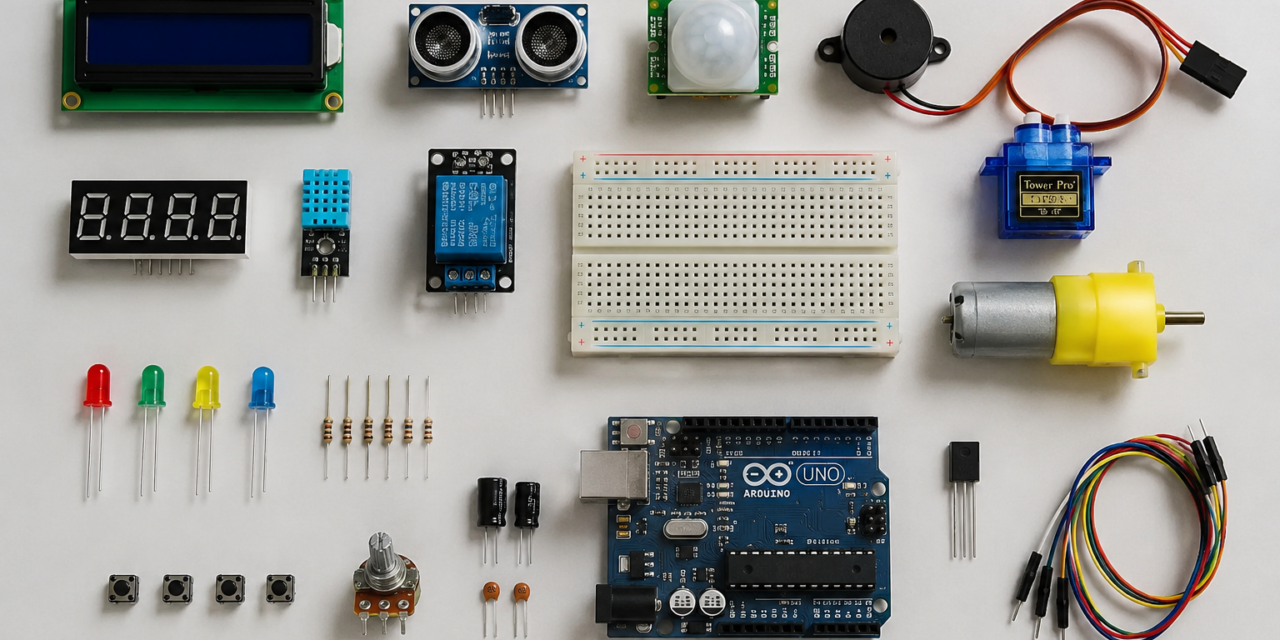
Electronic Components are the basic building blocks of an electronic circuit. Each component has a specific function, such as controlling the flow of current, storing electrical energy, producing light, or switching signals. When these components are connected correctly, they work together to perform a useful task in electronic devices like mobile phones, computers, robots, and other electronic systems.
Examples of electronic components:
- LED (Light Emitting Diode)
- Resistor
- Transistor
- Capacitor
- Diode
1. LED
LED (Light Emitting Diode) is an electronic component that emits light when electric current passes through it. It is commonly used as an indicator, for lighting, and in display systems. LEDs consume very little power, last for a long time, and are available in different colors.

2.Resistor
Resistor is an electronic component that controls or limits the flow of electric current in a circuit. It helps protect other electronic components from too much current, preventing them from getting damaged. Resistors are used in almost every electronic circuit to ensure that the circuit works safely and properly. Their resistance is measured in Ohms (Ω).

Types of resistor
| Type of Resistor | Usage |
| Fixed Resistor | Used to limit current with a fixed resistance value. |
| Thick Film Resistor | Used in general electronic circuits because it is low-cost and reliable. |
| Thin Film Resistor | Used where high accuracy and precision are required. |
| LDR (Light Dependent Resistor) | Used to detect light in automatic street lights and light sensors. |
| Potentiometer | Used to adjust volume, brightness, or voltage |
| Trimming Pot (Trimmer) | Used for fine adjustment and calibration of electronic circuits. |
| Surface Mount Resistor (SMD) | Used in compact electronic devices like mobile phones and laptops. |
| Thermistor | Used to sense and control temperature. |
| Rheostat | Used to control the flow of current in a circuit. |
| Varistor | Used to protect circuits from high-voltage surges. |
| Wire-Wound Resistor | Used in high-power circuits where more current can flow. |
Tinkercad
Tinkercad is a free online software used to design 3D models, electronic circuits, and basic coding projects. It allows users to create, test, and simulate circuits using components like Arduino, LEDs, resistors, and sensors without using real hardware. It is easy to use and is widely used by beginners, students, and makers for learning electronics and 3D design.
Tinkercad Simulation
A simple LED circuit created in Tinkercad using a 3V coin cell battery, resistor, LED, and connecting wires. When the simulation is started, current flows through the circuit, causing the LED to glow. The resistor limits the current to protect the LED from damage.

A simple LED circuit in Tinkercad using a 9V battery, resistor, LED, and connecting wires. The battery supplies power to the circuit, and when the simulation is started, the LED lights up. The resistor limits the current, protecting the LED from damage and ensuring the circuit works safely.

A light-controlled LED circuit designed in Tinkercad. It uses a 9V battery, LDR (Light Dependent Resistor), resistor, transistor, and LED. The LDR detects the light level, and based on the amount of light, it controls the transistor, which turns the LED ON or OFF automatically.

A simple LED circuit built on a breadboard using a 9V battery, resistor, LED, and connecting wires. The battery supplies power through the breadboard, and the LED glows when the circuit is completed. The resistor limits the current to protect the LED and ensure the circuit operates safely.

A basic Arduino Uno circuit connected to a breadboard, LED, and resistor in Tinkercad. The Arduino Uno provides power to the breadboard, and the LED is connected through a resistor to protect it from excess current. This setup is commonly used to learn basic Arduino programming and LED control.

An Arduino Uno connected to a breadboard with three LEDs and resistors. The Arduino supplies power to the breadboard, and each LED is connected through a resistor to limit the current. This circuit is commonly used to learn how to control multiple LEDs using Arduino programming.

An Arduino Uno connected to a breadboard with three LEDs (red, yellow, and green), a push button, and a resistor. The Arduino provides power and controls the LEDs through programming. When the push button is pressed, the Arduino can change the LEDs’ operation, making this a basic input-output circuit used for learning Arduino and electronics.

An Arduino Uno connected to a breadboard with an LED, push button, and resistor. The Arduino provides power to the circuit, while the push button acts as an input to control the LED. When the button is pressed, the Arduino can turn the LED ON or OFF through programming.

A 9V battery, resistor, transistor, breadboard, and a multimeter connected in ammeter mode. The multimeter is connected in series to measure the current flowing through the circuit, and it displays a current of 19.9 mA. This setup is used to understand how to measure current in an electronic circuit.

A 9V battery, resistor, LED, breadboard, and a multimeter connected in voltmeter mode. The multimeter is connected in parallel across the LED to measure its voltage, and it displays 2.20 V. This setup is used to measure the voltage across a component in an electronic circuit.
Paper Circuit
Paper Circuit is a simple electronic circuit made on paper using copper tape, an LED, a coin cell battery, and other basic components. Instead of using a breadboard or PCB, the components are connected on paper with conductive tape. Paper circuits are easy to make and are commonly used for learning electronics, greeting cards, art projects, and educational activities.


Series Circuit
A series circuit is a circuit in which all the components are connected one after another in a single path. The same current flows through every component. If one component stops working, the entire circuit stops working.
Flap Circuit
A flap circuit is a simple paper circuit in which a paper flap acts like a switch. When the flap is closed, it completes the circuit and the LED glows. When the flap is opened, the circuit breaks and the LED turns OFF.
Parallel Circuit
A parallel circuit is a circuit in which the components are connected in separate paths. Each component gets the same voltage and works independently. If one component fails, the other components continue to work.


Making and completing of Paper circuits
Then in Fab Lab, we built a simple LED lighting circuit on an actual breadboard using a battery, LED, resistor, and connecting wires. We connected all the components correctly and tested the circuit. When power was supplied, the LED glowed successfully, helping us understand the practical working of a basic electronic circuit.

Materials Used
- Breadboard
- 9V Battery
- 9V Battery Connector
- Jumper Wires
- LED (Light Emitting Diode)
- Resistor
- Connecting Wires


We successfully built and tested the LED circuit on the breadboard, and the LED glowed, confirming that the circuit was working correctly.
We also added a switch to the board to control the LED.
|


Group Assignment
During the group assignment, we learned how to use a digital multimeter to measure voltage, current (ampere), and resistance in an electronic circuit. We also learned how to connect the multimeter correctly to check these electrical values safely and accurately.


Cirkit Desginer
Cirkit Designer is a software used to design, simulate, and document electronic circuits. It helps users connect components like Arduino, ESP32, LEDs, sensors, resistors, and batteries on a computer before building the real circuit.
Stimulation

An Arduino Uno connected to a breadboard with an LED, a resistor, and wires to make a simple electronic circuit.The Arduino provides power to the LED through the resistor, which helps protect the LED from too much current.an Arduino Uno connected to a breadboard with an LED, a resistor, and wires to make a simple electronic circuit.

The Arduino is connected to the breadboard using three wires.
The 5V and GND wires supply power to the breadboard.
The LEDs are connected through resistors so they light up safely without getting damaged.

The LED is connected to the Arduino through a 200 Ω resistor to protect it from too much current.
A push button is connected to a digital input pin to detect when it is pressed.
When the button is pressed, the Arduino turns the LED ON; when it is released, the LED turns OFF.

Three LEDs (red, yellow, and green) are connected to different Arduino digital pins through 200 Ω resistors.
A push button is connected to the Arduino to give an input signal when it is pressed.
When the button is pressed, the Arduino controls the LEDs to turn ON or OFF in the programmed order.

The LED is connected to the Arduino through a 220 Ω resistor to protect it from too much current.
A push button is connected to a digital input pin to send a signal when it is pressed.
When the button is pressed, the Arduino turns the LED ON, and when it is released, the LED turns OFF.
Practical using Ardunio
During the Arduino practical, we first placed all the required components on the Circuit Designer workspace. Next, we opened the Code section and selected Auto Generate, which automatically created the code based on the components used in the circuit. We then connected the wires according to the circuit design and uploaded the generated code to the Arduino. After the code was uploaded, the Arduino worked successfully, and we observed the LEDs blinking according to the program. This practical helped us understand the basic process of creating a circuit, generating code, and running it on an Arduino.
/*
 * Controlling three LEDs with a pushbutton.
 *
 * This code will light up three LEDs (Red, Green, Blue) sequentially when a
 * pushbutton is pressed. Each LED is connected in series with a 200 Ohm
 * resistor. The pushbutton is used to cycle through the LEDs. When the
 * button is pressed, the next LED in the sequence will light up, and the
 * previous one will turn off. If the button is held down, the LEDs will
 * continue to cycle.
 */

const int buttonPin = 2;      // Pin connected to the pushbutton
const int ledPins[] = {8, 9, 10}; // Pins connected to the LEDs
int ledIndex = 0;             // Current LED index
bool buttonState = false;     // Current state of the button
bool lastButtonState = false; // Previous state of the button

void setup() {
    // Initialize LED pins as outputs
    for (int i = 0; i < 3; i++) {
        pinMode(ledPins[i], OUTPUT);
        digitalWrite(ledPins[i], LOW); // Ensure all LEDs are off initially
    }

    // Initialize the button pin as input
    pinMode(buttonPin, INPUT);
}

void loop() {
    // Read the current state of the button
    buttonState = digitalRead(buttonPin);

    // Check if the button was pressed
    if (buttonState && !lastButtonState) {
        // Turn off the current LED
        digitalWrite(ledPins[ledIndex], LOW);
        /*
 * Controlling three LEDs with a pushbutton.
 *
 * This code will light up three LEDs (Red, Green, Blue) sequentially when a
 * pushbutton is pressed. Each LED is connected in series with a 200 Ohm
 * resistor. The pushbutton is used to cycle through the LEDs. When the
 * button is pressed, the next LED in the sequence will light up, and the
 * previous one will turn off. If the button is held down, the LEDs will
 * continue to cycle.
 */

const int buttonPin = 2;      // Pin connected to the pushbutton
const int ledPins[] = {8, 9, 10}; // Pins connected to the LEDs
int ledIndex = 0;             // Current LED index
bool buttonState = false;     // Current state of the button
bool lastButtonState = false; // Previous state of the button

void setup() {
    // Initialize LED pins as outputs
    for (int i = 0; i < 3; i++) {
        pinMode(ledPins[i], OUTPUT);
        digitalWrite(ledPins[i], LOW); // Ensure all LEDs are off initially
    }

    // Initialize the button pin as input
    pinMode(buttonPin, INPUT);
}

void loop() {
    // Read the current state of the button
    buttonState = digitalRead(buttonPin);

    // Check if the button was pressed
    if (buttonState && !lastButtonState) {
        // Turn off the current LED
        digitalWrite(ledPins[ledIndex], LOW);
Following was the material used

Arduino Uno board – A microcontroller development board.
Breadboard – Used for building circuits without soldering.
USB A to USB B cable – Used to connect the Arduino to a computer.
Green LED (Light Emitting Diode) – Two green LEDs are visible.
Resistor – Likely around 220 Ω or 330 Ω, commonly used with LEDs.
Jumper wires – Two jumper wires (black and white) for making connections on the breadboard.


Process of installation

Issue:
The LED was not blinking because I connected the jumper wires to the wrong pins. This was my mistake while setting up the circuit. With the help of my ma’am, I checked the connections, corrected the wiring, and the LED started blinking successfully.

Then after making the first LED blink, we connected 3 LEDs and 3 jumper wires to the Arduino. We placed the LEDs on the breadboard and connected the jumper wires to the correct pins. Then, we uploaded the code to control all three LEDs.


We successfully did it
Then making changes in the (Dealy and loop) we make the various blinks
one after one light will get on off after set seconds


We removed 2nd led and there we added buzzer and saw how that aslo works

Soldering gun
A soldering gun is an electrical tool used to melt solder and join electronic components or wires together. It works like a soldering iron but heats up more quickly and is usually used for heavier electrical work.

Zero PCB
A Zero PCB (Zero Printed Circuit Board) is a blank prototype circuit board with isolated copper pads and no pre-made electrical connections, used for manually assembling and testing electronic circuits.

Practical on Zero PCB

- Zero PCB
- 9V Battery –
- Battery Snap Connector
- Yellow LED
- Resistor
- Hook-up Wire
- Stripper Tool
Installation

EDA Tools
Electronic Design Automation (EDA) is the use of specialized software tools to design, simulate, verify, and prepare electronic circuits and computer chips for manufacturing. These tools help engineers create complex digital and analog circuits, check that they work correctly, identify and fix errors before production, and improve performance. By automating many design tasks, EDA tools reduce development time, lower costs, and increase the reliability and quality of electronic products.

Examples of EDA software:
- KiCad
- Eagle
- EasyEDA
- OrCAD
KiCad
KiCad is a free computer software used to design electronic circuits and printed circuit boards (PCBs). It helps people draw circuit diagrams, arrange electronic parts, and create the design needed to make a real circuit board.
Installation process of KiCad
Step 1

Step 2

Step 3

Step 4

Step 5

Step 6

Step 7

Making Circuit on Schematic Diagram

I took symbols from the libraries

This is a simple LED circuit. The power is connected through the 2-pin connector (J1), and the current flows through the resistor (R1) and then the LED (D1). The resistor protects the LED from too much current, allowing it to glow safely.
PCB Editor

PCB layout is created in the KiCad PCB Editor, where components are placed and connected using tracks.
3D Viewer

This is done in the KiCad 3D Viewer, where we can view the final PCB design in a 3D model before manufacturing.