Introduction :
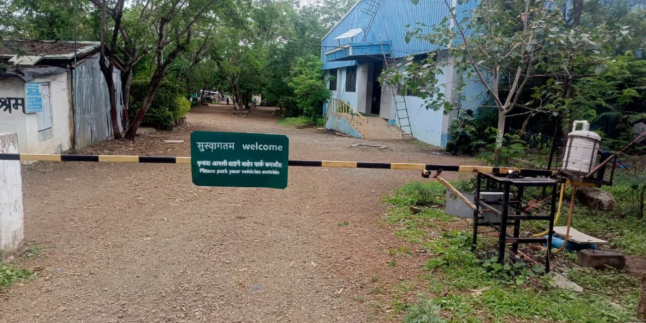
The main aim of this project at Vigyan Ashram, Pabal is to develop a Gravity-Based Water Weight Controlled Gate. The system uses a 40V DC water pump to fill an upper tank. As the water weight increases, gravity causes the gate to move to mobile oprate. Water then drains back to the lower tank, allowing the gate to return to its original position. This project demonstrates the practical application of gravity, fluid mechanics, and simple mechanical automation.
Objectives :
1) To design a gravity-based automatic gate mechanism.
2) To use water weight for opening and closing the gate.
3) To reduce the dependence on high-power gate motors.
4) To demonstrate gravity and fluid mechanics in a practical application.
5) To develop an economical and energy-efficient gate system.
Problem Statement :
This project aims to develop a gravity-based water weight controlled gate that uses water as the driving force, reducing power consumption and simplifying the gate mechanism.
Methodology :
1) Install the upper and lower water tanks.
2) Mount a 40V DC water pump.
3) Connect the tanks using water pipes.
4) Provide a controlled outlet for water drainage.
5) Test the opening and closing operation.
Working Principle :
The 40V DC pump pumps water from the lower tank to the upper tank. As the upper tank fills, its weight increases. Under the action of gravity, the increased weight causes the gate to move. Water then flows back through a small outlet pipe into the lower tank. As the upper tank becomes lighter, the gate returns to its initial position. This cycle repeats automatically.
Working Components :
1) Upper Water Tank – Stores water to create the required weight for gate operation.
2) Lower Water Tank – Collects drained water and supplies it back to the pump.
3) 40V DC Water Pump – Pumps water from the lower tank to the upper tank.
3) PVC Pipe – Transfers water between the tanks.
4) Counterweight (Stone) – Balances the gate and helps it return to its original position.
5) Pivot Shaft and Bearing – Allows smooth rotation of the gate.
6) Power Supply – Provides electrical power to the water pump.
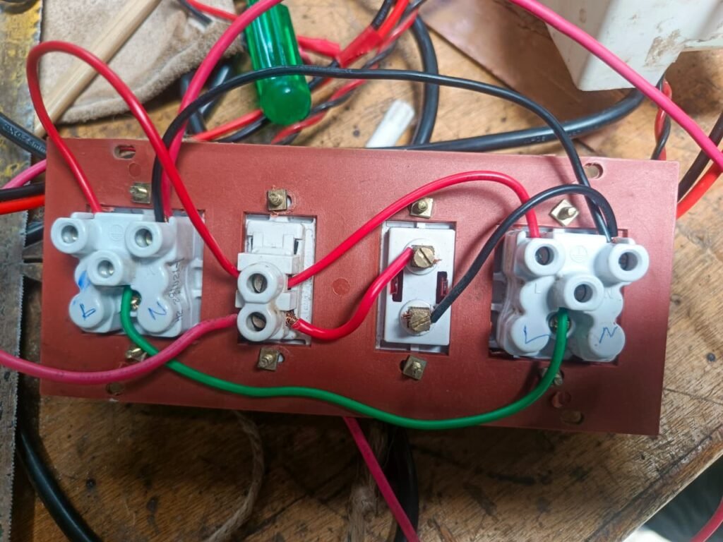
7) Control Switch – Used to turn the pump ON and OFF.
Work Completed :
1) Installed a 40V DC water pump for transferring water from the lower tank to the upper tank.
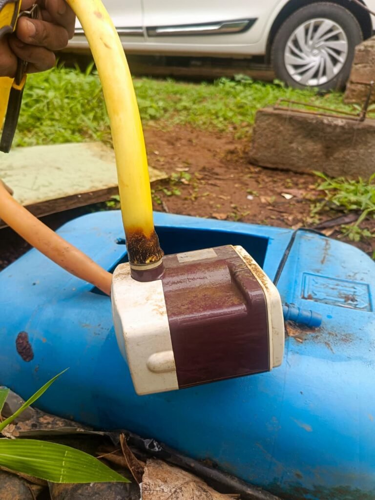
2) Completed the electrical wiring and power connections for the pump.
3) Added a stone counterweight to balance the gate and assist its return movement.
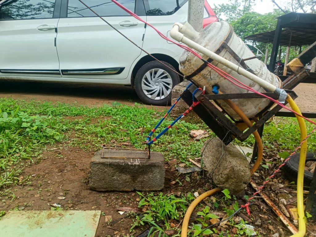
4) Adjusted the system so that the gate opens completely in approximately 25–30 seconds.
5) Designed a counterweight locking mechanism, allowing the stone to be fixed in the upper position whenever the gate needs to remain open.
What I Learned During This Project :
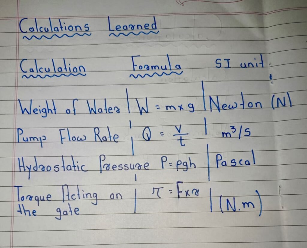
1) Gravity – The water-filled tank moves downward due to gravitational force.
2) Newton’s Second Law – The weight of the water generates the force required to lift the gate.
3) Fluid Mechanics – Water flows between the upper and lower tanks through PVC pipes.
4) Hydrostatic Pressure – Water pressure controls the drainage through the outlet pipe.
5) Counterweight Principle – The stone counterweight helps pull the gate back to its original position after the water drains.
6) Conservation of Energy – Electrical energy from the pump is converted into gravitational potential energy and then into mechanical energy to lift the gate.
Project development report : ( july 3rd week )
| DATE | DAY | WORK COMPITED |
| 15 Jul 2026 | WENSEDAY | Understood the gate mechanism and completed the electrical wiring connections. |
| 16 jul 2026 | – | |
| 17 jul 2026 | FRIDAY | Installed the 40V DC water pump and started testing the system. |
| 18 jul 2026 | SATURDAY | Completed pump installation and adjusted the system so that the gate opens in approximately 25–30 seconds. |
| 19 jul 2026 | SUNDAY | Installed a stone counter weight and developed a locking mechanism to keep the gate in the open position whenever required. |
Next Development : Plan– Mobile-Based Control System
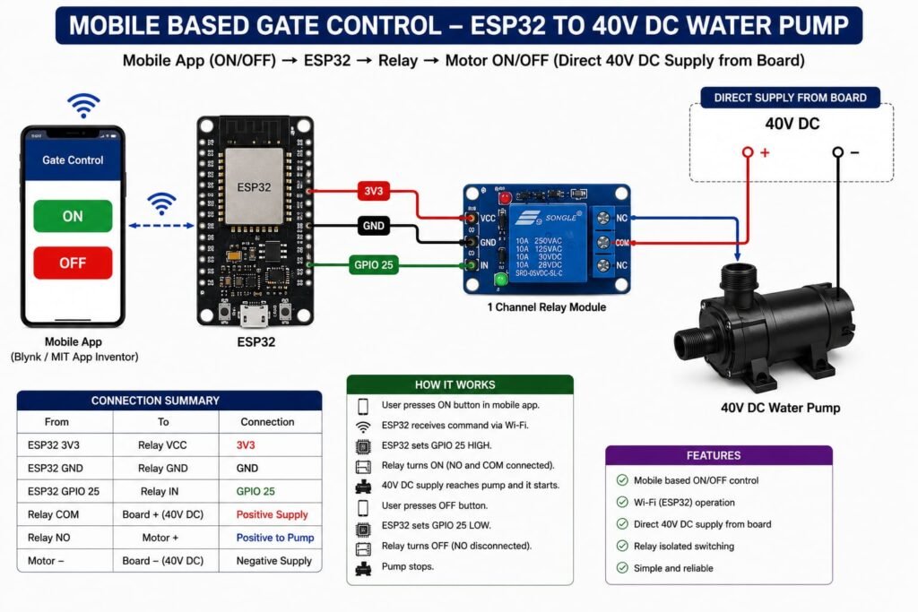
In the next phase, the gate will be controlled using a mobile phone. An ESP32 will receive commands from a mobile app and switch ON the 40V DC water pump through a relay. The pump will fill the upper tank, increasing its weight and lifting the gate. When the water drains back to the lower tank, the gate will automatically return to its original position. This system will provide wireless, remote, and smart gate operation.
Required components and its function :
1) ESP32 – Receives commands from the mobile app.
2) Relay Module – Switches the 40V DC pump ON/OFF.
3) 40V DC Water Pump – Pumps water to the upper tank.
4) Mobile App – Controls the gate remotely.
5) Water Tanks – Store and transfer water.
6) PVC Pipe – Carries water between the tanks.
7) Limit Switch – Stops the pump when the gate is fully open.
8) Power Supply – Provides electrical power.
9) Connecting Wires – Connect all electrical components.
Working :
The user controls the gate through a mobile app. The ESP32 receives the command and switches ON the 40V DC water pump. Water fills the upper tank, increasing its weight and lifting the gate. When the water drains back to the lower tank, the stone counterweight automatically returns the gate to its closed position.