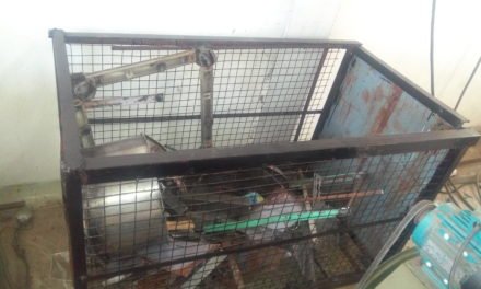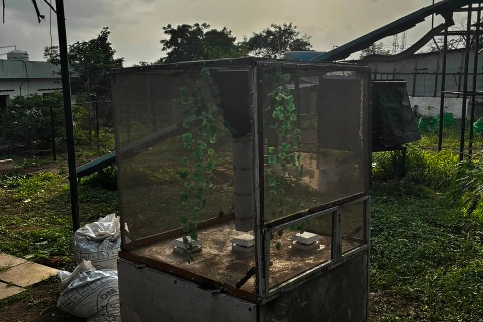
The black soldier fly (Hermetia illucens) is a non-pest insect native to the Americas but now found worldwide, valued for its larvae’s ability to convert organic waste into protein-rich biomass and compost. It plays a major role in waste management and animal feed production.
Life Cycle
Eggs: Laid in clusters near decaying matter.
Larvae: The most important stage— consume organic waste, reducing volume by up to 50–60%.
Pupae: Transition stage before adulthood.
Adults: Live only about 5–8 days, do not feed, and are harmless (they don’t bite or spread disease).
When Larvae turns into Pupae and adult flies come out from Pupae when temperature is below 30°C and humidity above 80% RH , it goes towards the light and they need light to see blue/ green stripes on female BSF which attracts male BSF for the mating process. Since suitable temperature and humidity for BSF is not constant throughout the year.
Therefore, Pratheen Eco Solution treating biodegradable waste through BSF needs an incubator to maintain the suitable environment so the mating process can be cultivated throughout the year. And in current breeding chamber there is an obstacle i.e. choking of fogger due to hard water and formation of algae on cooling pads is reducing air flow.
July 1 2026
Objectives:
To design a control algorithm of Incubator for BSF mating chamber to maintain temperature range 25°C to 30°C and humidity range 65% to 80% RH inside the mating chamber.
In April 2026, Pabal had an extreme weater condition of 40°C and 15% RH ambient air. So we are trying to model how we can keep our favourable condition in such extreme condition.
July 3 2026
Idea discussion with Dr. Arun Dixit:
Idea 1
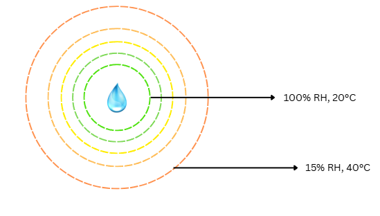
Image 1
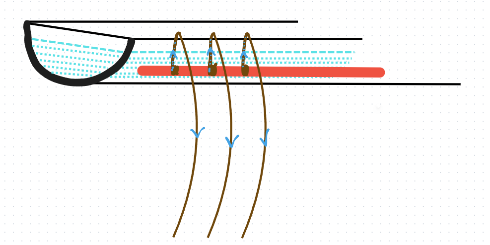
To model how Relative Humidity and temperature changes from centre of droplet to distance r.
Idea 2
How different size of droplet of rainfall humidify the air and how evaporation of moisture from soil contributes to relative humidity.
Idea 3
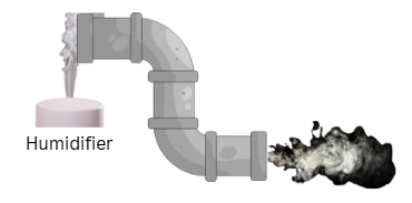
Image 2
Using UV Humidifier to pass humid air in breeding chamber
Idea 4
Reverse Shower (fountain) since rate of evaporation depends upon size of droplet,wind speed,retention time and humidity of air.
July 4 – 5 , 2026
Tried to create mathematical model of our condition but due to complexity I pivoted to do simulation on COMSOL Multiphysics and learning the software while working on it with the help of Google Gemini.
July 6 – 12 , 2026
Due to divergence in simulation and complexity in reverse shower fountain we (me and Dr. Arun Dixit sir) discussed and came with broadly two things
- What if we put fountain inside the chamber?
- Adding PVC pipe at edge – top of chamber water flows and jute rope will be passed through PVC such that it’s vertically parallel to sidewalls of chamber, at centre top of chamber is open with gradual perforated central pipe and fan and this whole setup is enclosed in polyethlene with slit at bottom so air travels upwards againts wet jute rope due to exhaust of air from central duct fan.
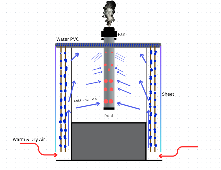
Image 3
Some repair work was done on existing chamber:
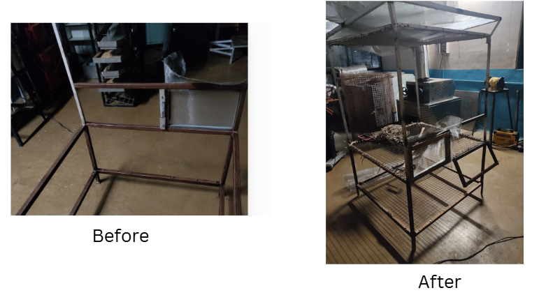
Image 4
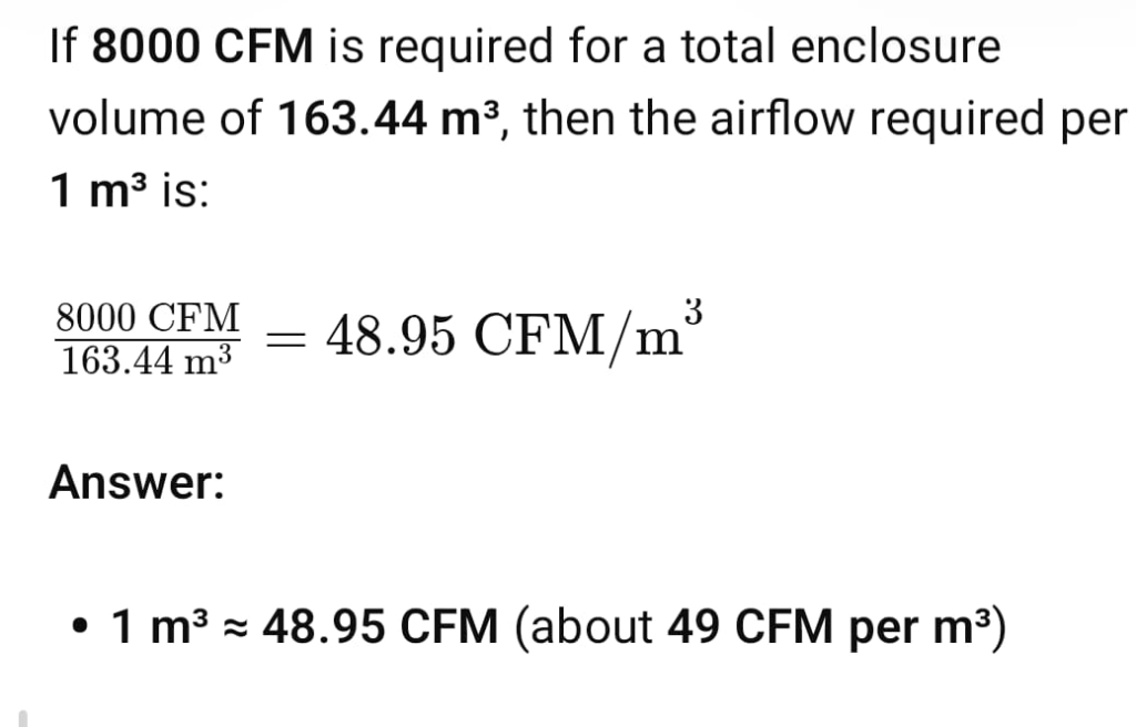
Polyhouse near entry point hai 163.44 cu.m with 8000 CFM. So CFM for 1 cu.m
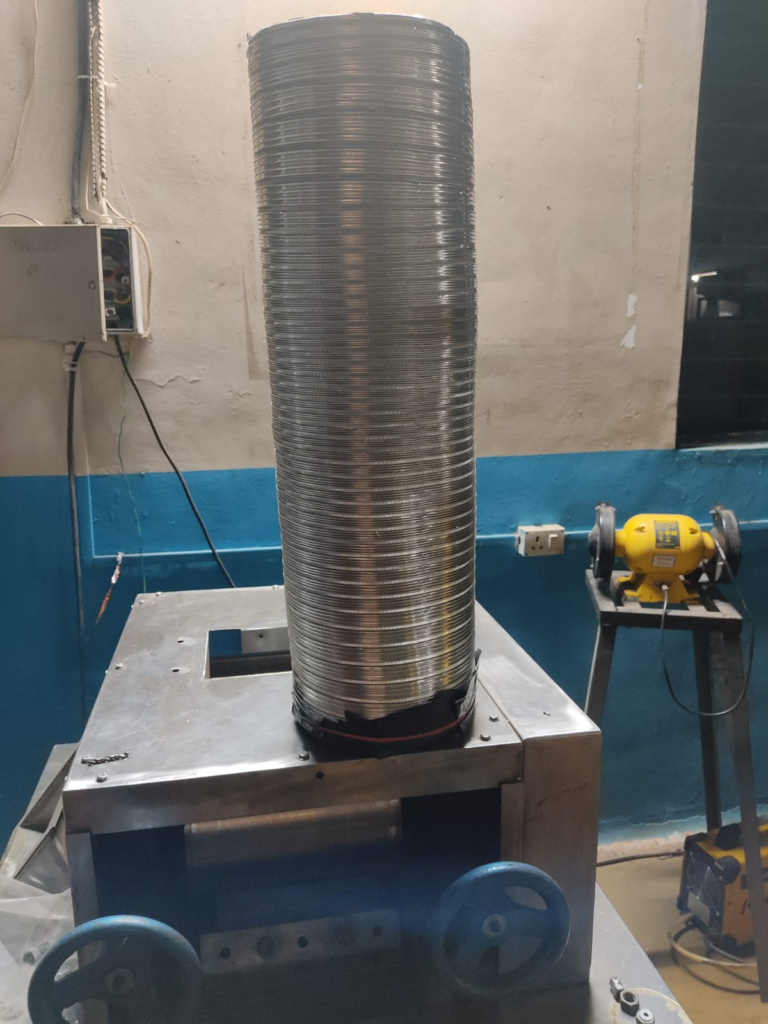
Central Duct
Image 5
July 13 – 19 , 2026
Since aluminium duct has grooves which is ideal for BSF to lay eggs, as BSF fly lay eggs at dry and very small gaps. We have to maintain suction of air to be almost even as height changes bottom to top, also a way to prevent BSF fly from entering into central duct. System would have loss if flies dies and layed eggs are not possible to retrive/collect.
A simple mathematical model to decide size of holes from top to bottom
Google Colab notebook link contains code which help us decide size of holes at each level top to bottom
PVC pipe cut and a solid material kept in PVC tied with jute rope so that water travels through jute rope by capillary action and evaporative cooling will occur. Through hole wasn’t made in PVC because it will lead to uneven rate of drizzling of water which will lead to uneven cooling.
Image 6
July 20 – 27 , 2026
Jute rope knots were made manually, making the process time-consuming.
July 28 – Aug 2 , 2026
Since fan diametre is of 12″ (304.8mm) and PVC diametre available in Pabal is 110mm. Therfore below is CAD of funnel type structure which will be made of tarpaulin sheet after doing laser cut.
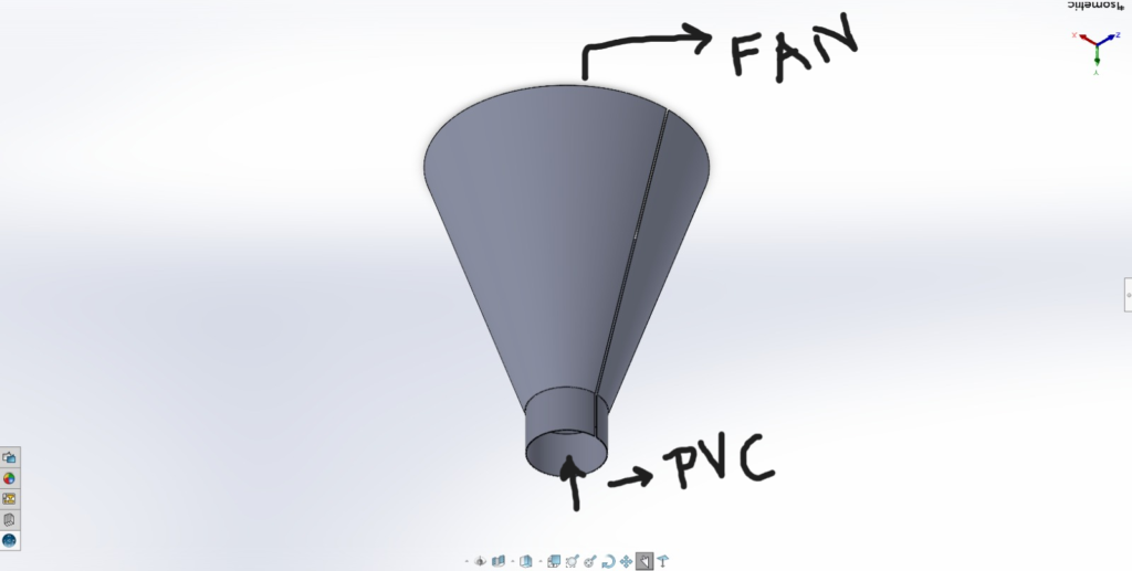
Image 7
Aug 3 – Aug 9 , 2026
Dixit sir pointed out one failure point with tarpaulin sheet that fan is sucking the air therefore tarapaulin sheet will not retain it’s shape, therefore to maintain structural shape we looked for different way like creating ring from 1″ square mesh or some wooden emboidary hoop ring structure. Then @shreyash-malode said how about we use cycling spokes.
To make cone type strucutre we have used black tarpaulin sheet and used fevi kwik to stick it on fan outer frame as shown in the following image:
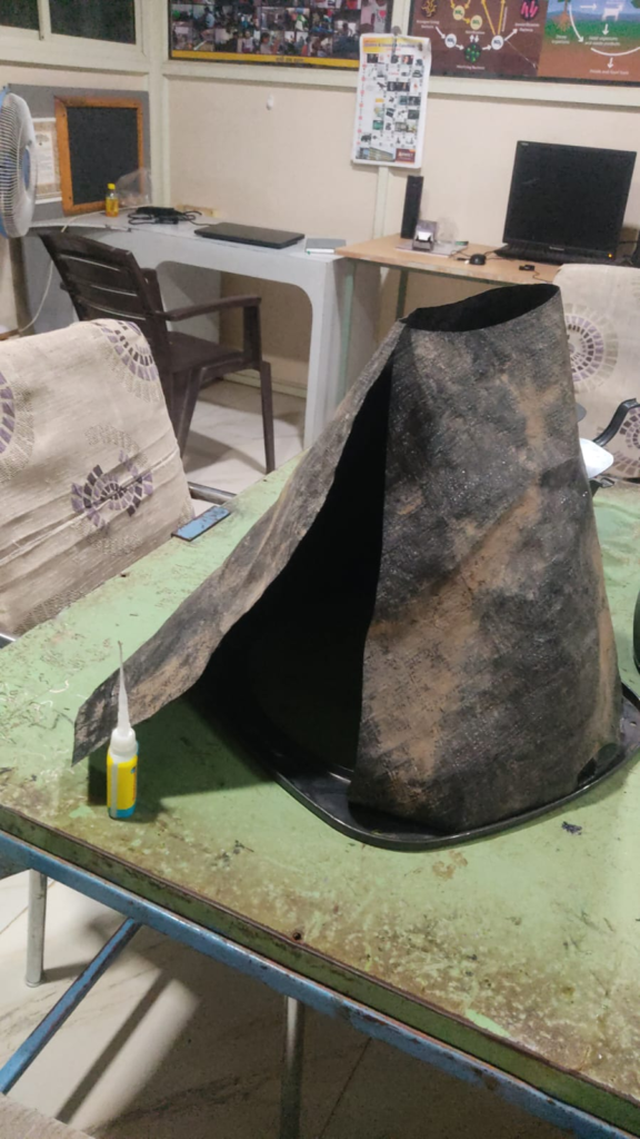
To make cone type strucutre we have used black tarpaulin sheet and used fevi kwik since both comes under plastic type material and exhaust fan outer frame is also of plastic (to stick it on fan outer frame as shown here)
Image 8
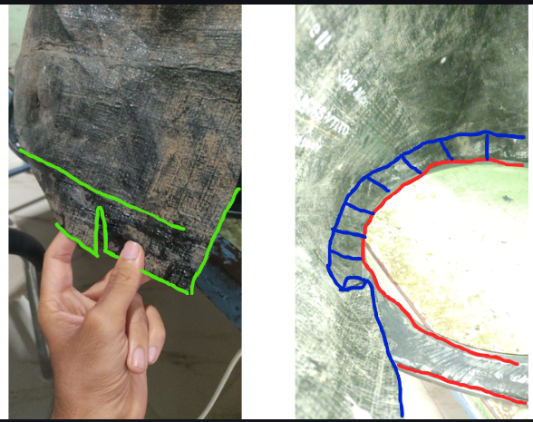
Challenge : While sitting tarpaulin on fan outer frameit was forming irregular shape and therefore unable to form cone type structure, therefore as a solution we put some cuts to make it discrete and than curved from inside so sheet and body can stick properly and when is put inside there won’t be any slots for air leak. (Inspired from Nikhil Project learnings)
Red highlight is edge of fan outer frame and blue highlight is tarpaulin.
Image 9
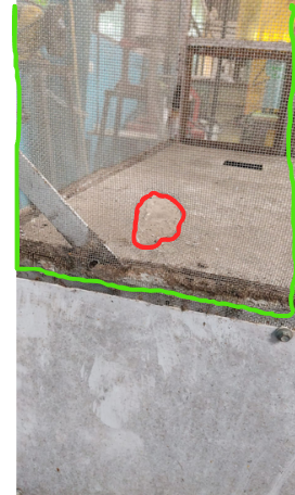
Casualty of project while attaching net by drill machine.
Image 10
With the help of Chandrabhan , Nikhil, @shreyash-malode and @samruddhi-shinde chamber was repaired back to it’s orignal condition and gaps were filled using silicone sealant to avoid loss of flies.
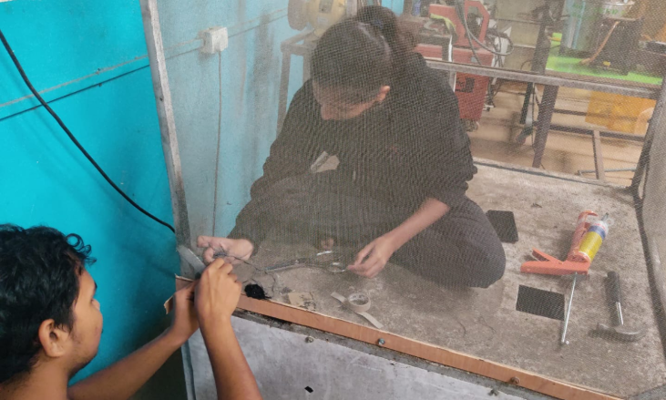
Image 11
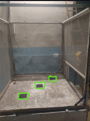
Since chamber is open from above and fine mesh is put on the chamber. Therefore during rainfall, water droplets enter through the three square ventilation slots. The rainwater travels into the lower black box section and causes water leakage around the pupa chamber. As a result, the BSF pupae are exposed to excess moisture, which can reduce emergence rates and damage the pupae.
Image 12
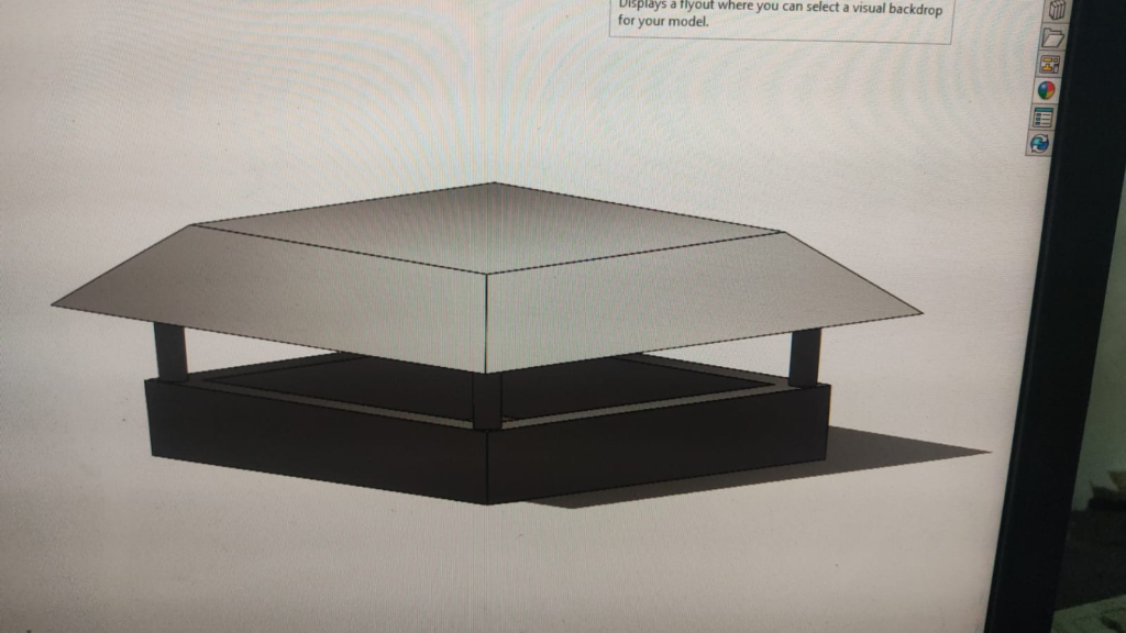
This cap blocks rainwater from entering the black box while ensuring that flies emerging from the pupae can come out without restriction.
Image 13
Since this whole 1 unit takes 5.5hr to 3D print so they are kept for printing but they will look like the following image generated using AI for temporary purpose: (Light test is pending to be done to validate hypothesis)
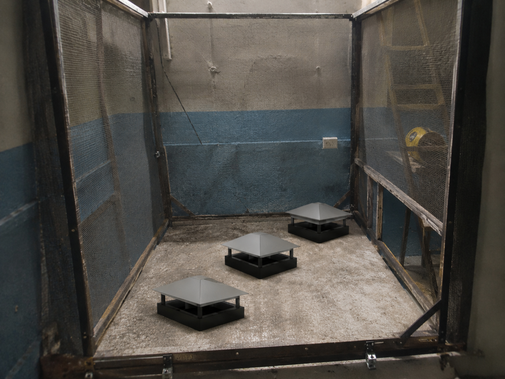
Image 14
Aug 10 – Aug 16 , 2026
I had a concern that we are putting cap on holes but will it affect light inside in blackbox.
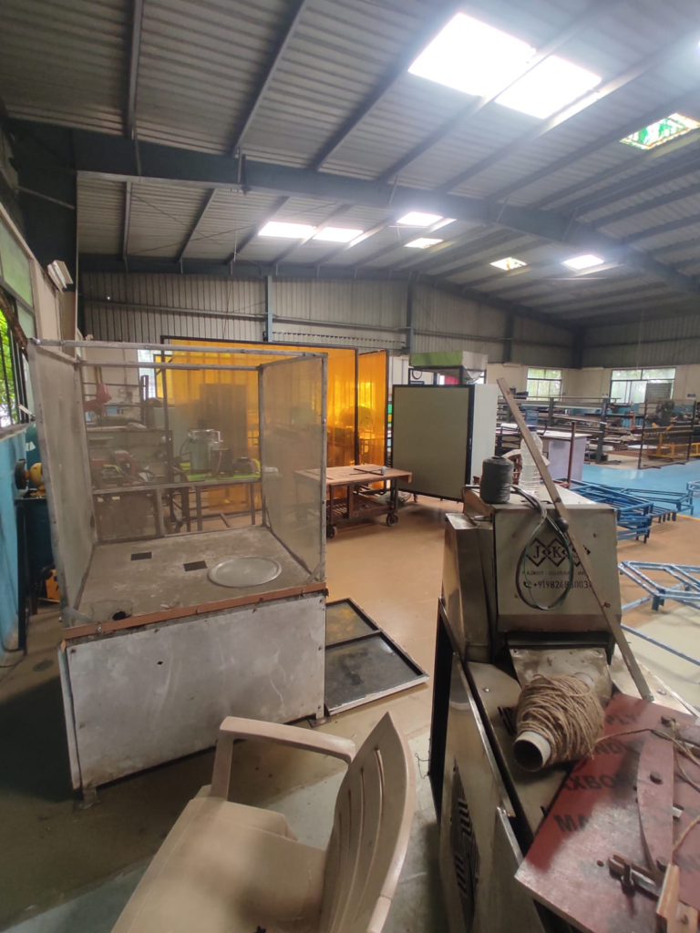
Light and Object condition.
Image 15
Light inisde the chamber as per above light and object condition.
Video 1
All Three Holes covered.
Video 2
After one Cap printed
Video 3
All 3 caps are placed
Video 4
From our central duct we are sucking humid air present inside chamber and exhausted out so in order to avoid squeeze of tarpaulin sheet we used cycling spokes which provide structure and links fan frame with PVC pipe.
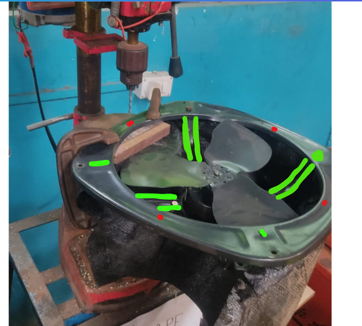
Red dot is where cycling spokes will be fixed and that hook type end of cycling spokes will be attached to PVC pipe.
Correction: Fan outer frame is metal body
Image 16
With the help of Hritik, pipe got attached with fan frame using cycling spokes.
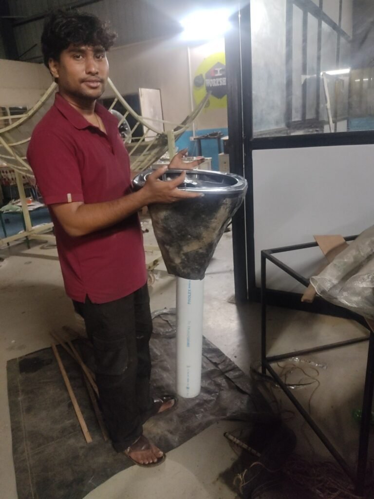
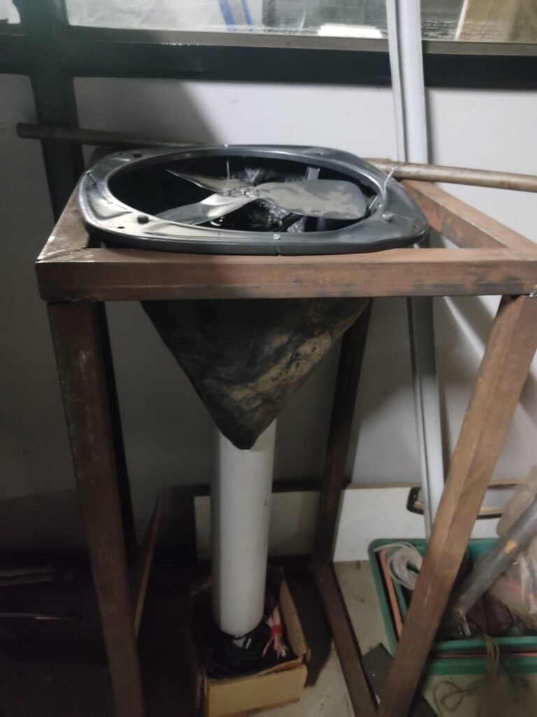
Image 17
Now next challenge is to hang this central pipe + Fan and othe part like holes on PVC to suck air almost unifomly and covering base of pipe to create pressure in pipe.
Let’s call Central pipe + Fan = exhaust unit.
To hang exhaust unit I asked for Chandrabhan’s help to manufacture and weld and idea is as follows:
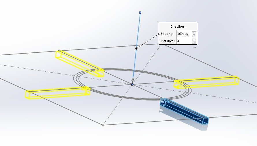
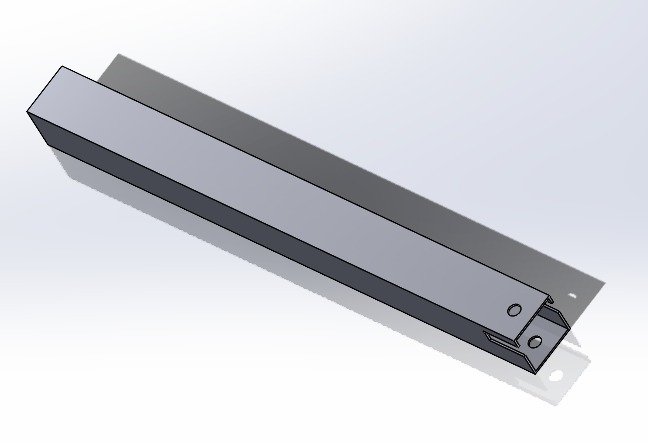
Image 18
Aug 17 – Aug 23 , 2026
Put slots, holes and bolted on square tubes pair of 265 mm and 272.5 mm as decided shown in below image, so while putting net from above there won’t be gap for flies to escape and slots will hold fan.
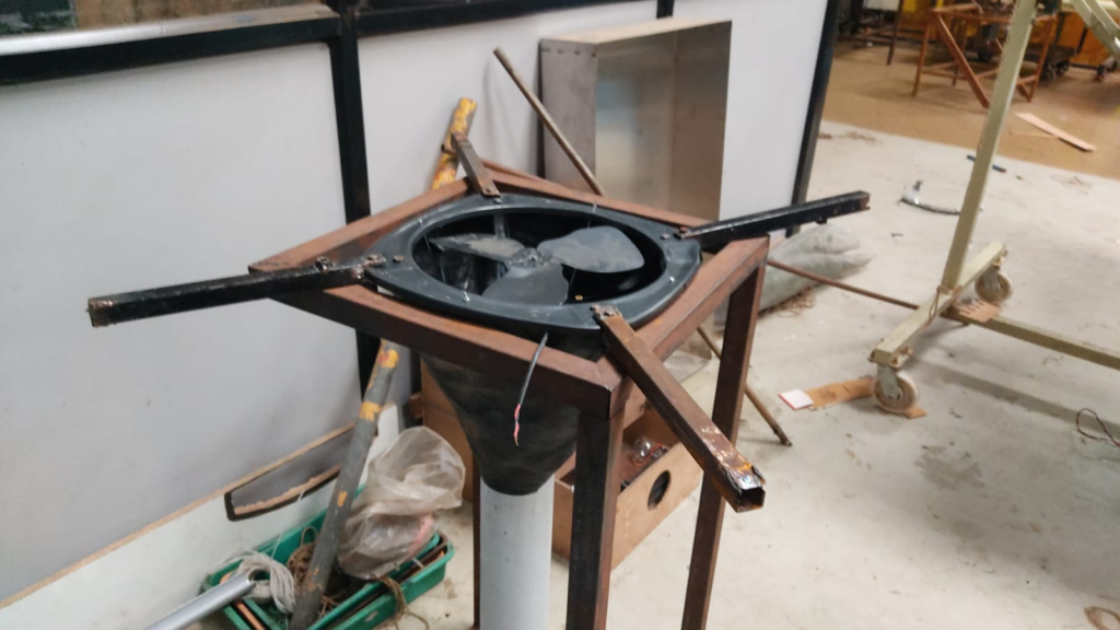
Image 19
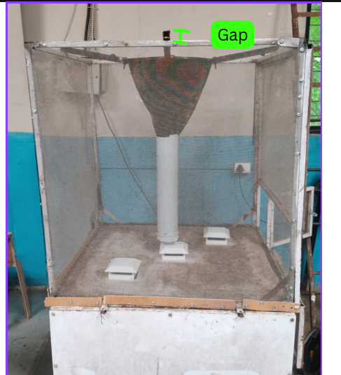
Checking feasibility whether exhaust unit with support structures will be their properly or not.
And as we can see in image current positioning if we weld directly that gap will be leak to BSF flies.
Image 20
Discussion with Dixit Sir
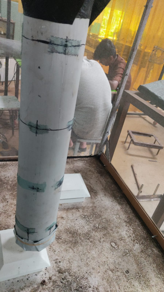
During the discussion, we tried to understand the primary heat transfer mechanisms inside the BSF breeding chamber.
Our current understanding is that solar radiation entering the chamber is absorbed by air, water, soil, and vegetation. Vegetation utilizes only a small fraction of the incoming solar energy for photosynthesis, while most of the absorbed energy is eventually converted into heat and re-emitted as long-wave infrared radiation.
The heated surfaces, particularly the soil and chamber structure, then transfer heat to the surrounding air. This creates warmer, less dense air which tends to rise due to natural convection.
Based on this reasoning, we discussed that the heat accumulated inside the chamber must be removed to maintain suitable breeding conditions. One possible mechanism is evaporative cooling, where evaporation absorbs thermal energy from the chamber air.
We also discussed whether complete PVC sheet exposure is necessary. Based on the present understanding, it appears that having approximately 60% exposed PVC may not create a significant issue, although this needs experimental validation.
To encourage natural air movement, a vertical PVC ventilation pipe was installed. The pipe contains 6 mm diameter mesh-covered holes arranged from bottom to top in the sequence:
- Bottom row to Top: 6,5,4,3 holes respectively
The expectation is that warm air generated inside the chamber will rise and escape through the ventilation pathway, promoting passive cooling through natural convection.
However, this remains a hypothesis and should be verified through smoke-flow visualization, temperature measurements at different heights, and comparison of chamber conditions before and after installation of the vent pipe.
Key Learning
The discussion highlighted the importance of distinguishing between theoretical understanding and experimental evidence. The current design is based on heat transfer principles, but its effectiveness must be confirmed through testing and measurement.
Image 22
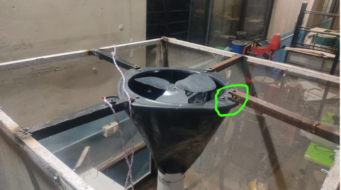
Image 23 Image 24
Steps we take to develop is we marked square tubes and their positions and welded them and later mounted fan so during mounting green highlighted rod was elevated so we did some adjustment instead of welding again because chamber square tube had more chances to get welding hole in second attempt.
And after exhaust unit mounting and electrical connection our plan was to cover up side part of chamber with mesh and start testing but one more challenge surfaced.
As we can see fan was supposed to exhaust air out but it was sucking air in. So we (Nikhil,Dharmesh and author) thought let’s put fan upside down as it’s sucking and throwing in PVC pipe.
Video 5
Even we flip fan it’s still sucking air inside.
Video 6
I have two hypothesis :
- Due to suction negative pressure is developed but air available in cone is getting sucked in.
- Or orifice created in PVC pipe are creating resistance for air to get suck in therefore air available in cone is getting pushed in PVC due to negative pressure.
To understand what’s really happening Nikhil, @samruddhi-shinde suggested to put dhoop/incense stick (5 to 6 units burn them for smoke) in PVC and turn exhaust ON to see actual behaviour of air.
Problem: Fan fins were getting obstructed by fan legs.
Observation: As nikhil righlty mentioned fan was tilted, and I find out it was due to loosen up of welded supports might be due to intrrmittent load while getting in and outside the chamber.
So by jerk that tilt is temporary fix.
Smoke Test
We burned 3 unit of dhoop and put it into steel cup, with plastic rope tied around we put incensed dhoop setup inside central PVC pipe the way we put coffin in graveyard.
Video 8 Image 24
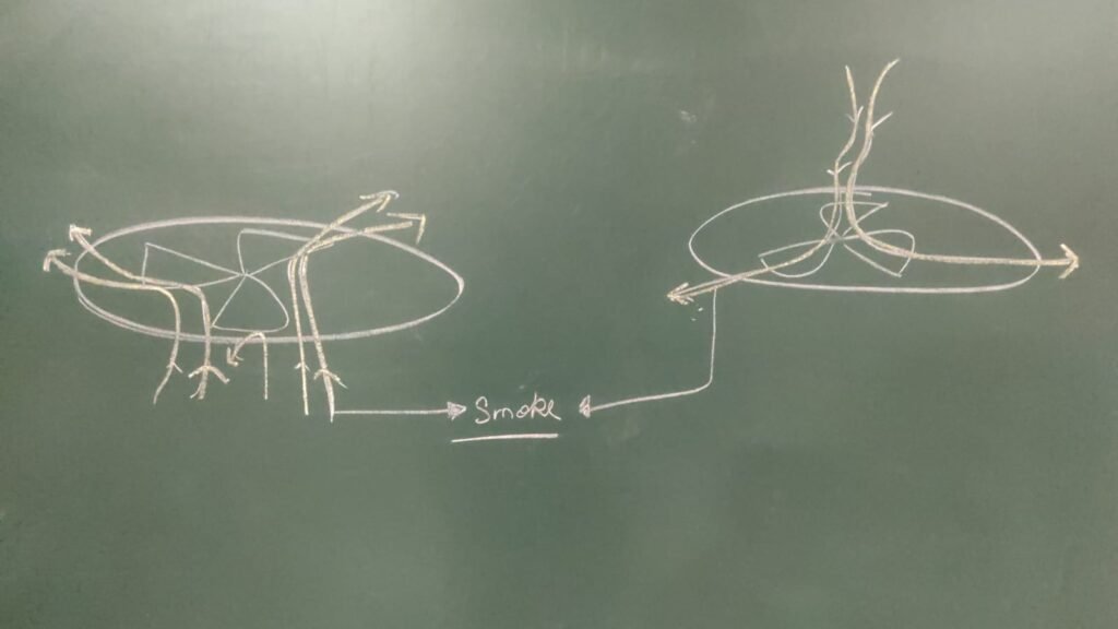
Observation: Based on smoke flow it looks like it works similar to centrifugal pumps, as smoke coming from below in ref. image 24 smoke folllowed blade or blade directed the airflow and in Video 5 what we thought smoke is going in was nothing but as see on Right hand side drawing in image 24 smoke gets suck at centre but follows blade path and flows out therefore exhaust is happening.
So we put mobile torch inside cone and turned fan ON and we put smoke outside the PVC pipeat first it was isible that holes/ orifice are not sucking air but then it was visible orifice are sucking air.
Life lesson: Observation and Interpretation can go wrong.
After covering chamber with mesh it is installed in it’s test condition.
Special thanks to @dharmesh-makvana, @nikhil-patil to help me with fabrication and assembly. Shout out to @shekhar-pawar , @bhanudas-daundkarsir and DBRT students like Chand, Sandip, Ganesh and many more who helped us in shifting the chamber.
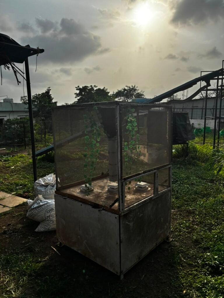
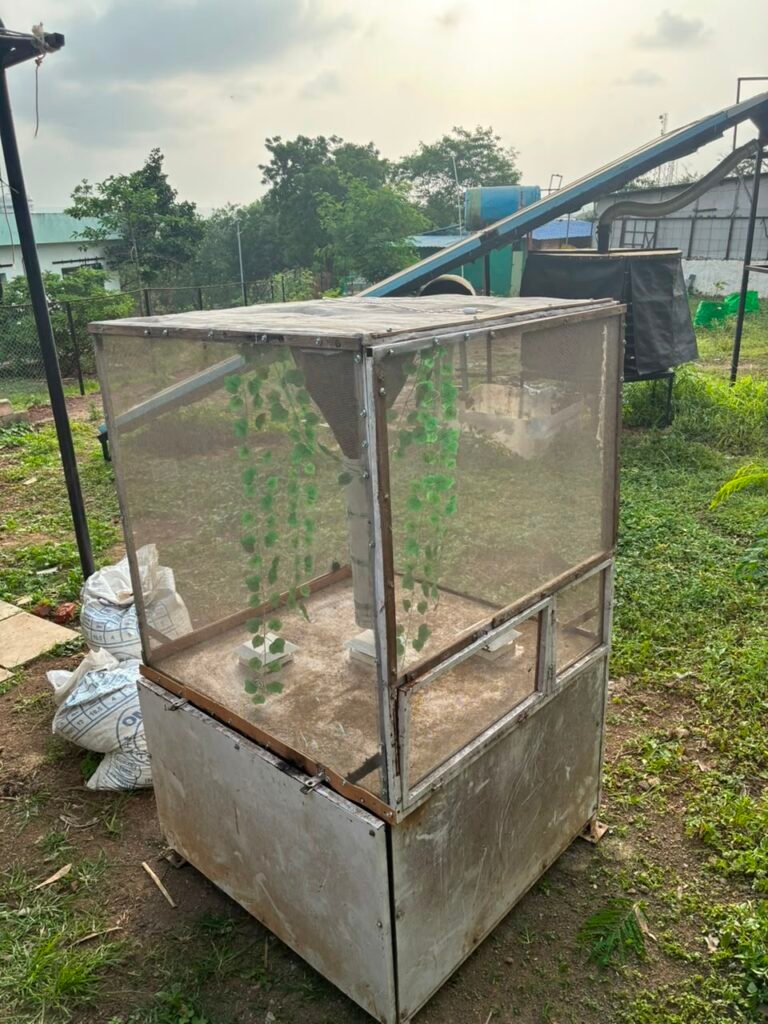
5 kg pupa loaded in black chamber and flies are visible.