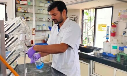
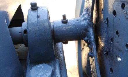
A Manifold is a fluid or gas distribution system or device that serves to bring many junctions into one place or a single channel into an many junctions.
Grey Water is clean waste water from baths, sinks, washing machines and other kitchen appliances.
Aeration (also called aerification or aeriation) is the process by which air is circulated through, mixed with or dissolved in a liquid or substance.
So basic purpose/idea of this project is to aeriate the grey water by using manifold.
But why we need to aeriate the grey water…??? The grey water is generally of high COD (Chemical Oxygen Demand) and the anaerobic bacterial growth is happen in the grey water thus anaerobic bacterial growth leads to odour from grey water. In order to reduce COD people use water Hyacinth (Jalparni), Tarrow Leaves, Canna Indica, Duck Weed, Cattail, Azolla but these plants doesn’t serves the purpose. It require additional support of aeration. That’s why Manifold is the Heart of the grey water recycle system.
Their are plenty number of manifold are available in the market but then also we are going for our custom design manifold. The reason behind it is, the manifolds that their in the markets are not designed according to the technical calculations.
The basic thing we are considered for designing for aeration manifold are:
- Size of bubble:
- Pressure on bubble:
When I am searching for the literature, I couldn’t get any data about the amount of aeration required. After discussing with the Arun Sir, we decided to start with something. We considered human as a system and start to collect data. We come to know across following information:
- A normal human takes 500 ml of air per inhale.
- we generally inhales about 20 times a minute.
- That means human inhales 10 liter air per minute.
- The inhale air consist of 21% of Oxygen
- The exhale air consist of 16% of oxygen
- That means only 5% of Oxygen (from air) is taken by lungs.
- That means only 500 ml oxygen is taken by lungs out of 10 liter air per minute.
- A well developed human lung have surface area about 60 m²
- That means 500 ml oxygen can be absorbed by 60 m² lung per minute
- Hence we require 167 ml air to be pumped per m² area per minute.
Let’s consider approx. 200 ml of air we have to pump per m² area per minute. We have three tanks of capacity 1800 liter , 450 liter and 350 liter in which we have to provide aeration. …………………………………………………………………………………………………………………………………………………………………………………………………………
Then I thought that, if I am talking about aeration of grey water, I should remove the food particles from it. We can remove food particles by:
- Filtration
- Settling
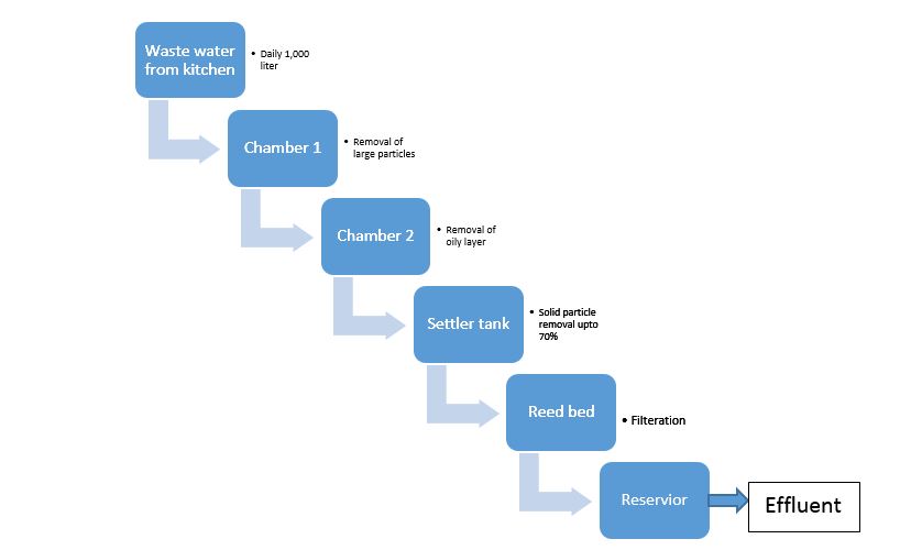
So I decided to place filter at each outlet of grey water and construct new settler tank. During the survey, We measure our daily consumption of kitchen water, its about 1,000 liters but in actual outlet reservoir we hardly could get 400 liters. So I started to find the leakages. I found that the sewage line is leak, so we decided to replace the whole sewage line rather to reconstruct it, in order to avoid the future problems. On other hand, I also had to check the outlet tanks are leak of not… We all knew that two tanks (out of the three) are surely leak, the only question is about the third one (1800 liter tank). But now a big question is how to find the tank is leak of not…??? I ask question to myself that why the level of water in the tank will decrease..??? I got two answers First is because of leakage and other is because of the evaporation of water. Therefore if the tank is not leak, the only reason to decrease level of water in the tank is evaporation of water. So we only need to check the in what rate the water gets evaporated but obviously, the evaporation rate will depend on the intensity of sunlight. So I became answer less to tell that the tank is leak or not. I was thinking about the solution for couple of days and suddenly i realize a intresting idea.
I take a bucket which is partially filled with water. I place the bucket near the tank which I want to test. Then I marked water level on both bucket as well as tank. The whole experiment is that, the water surface in the tank and water surface in the bucket both are exposed to same intensity sunlight that’s why the evaporation rate per unit area will be same. The decrease in level of water in bucket is only because the evaporation of water as the bucket is leak-proof. So I got one reference with which I can compare other. If decrease in level of both tank and bucket water is same then I can conclude that the tank is leak-proof otherwise not. After 24 hours, I again noted down the decrease in the water level. I found that decrease in level of water in bucket is 12 mm and that of tank is 26 mm and hence i come to know that this tank is also leak. Now, rather to reconstruct full tank, we preferred to do leak proofing of that.
As two tanks out of the three as well as whole sewage line need to reconstruct, we decided to proceed with totally new plan in which we can arrange everything as per our requirement.
Rough Plan:
Strainer:
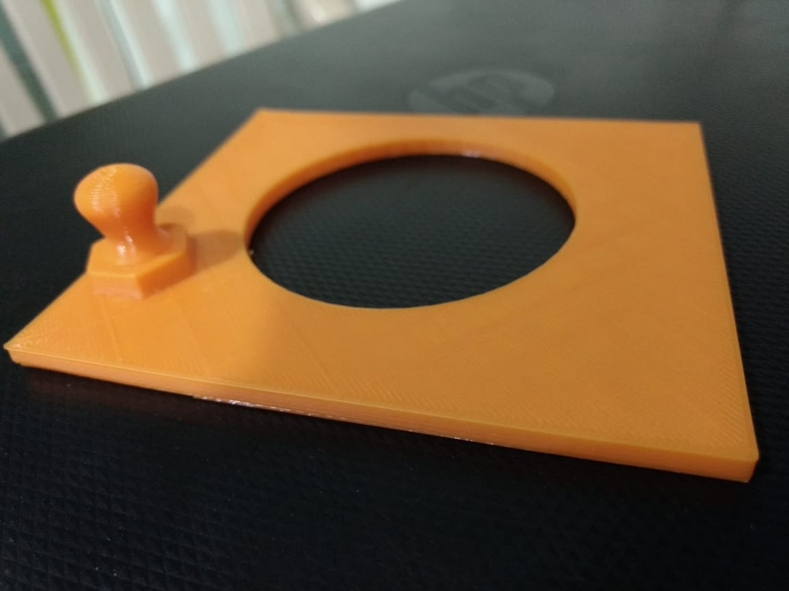
We decided to design each chamber and filter according to our convenience. I decided to 3D print a strainer (using 3D printer available at our Fablab) which can be fitted at the basin where all our students washes their plates. I created a CAD model using SOLIDWORKS software. The model is something looks like:

When I gone for print, I realize that it’s difficult to print the overhang part. 3D printer needs support to print overhang parts. Printing of extra supports leads to wastage of material also it increases the task of removing supports. So I break the designed CAD part into two parts which can print seperatly and later can be joined to each other.
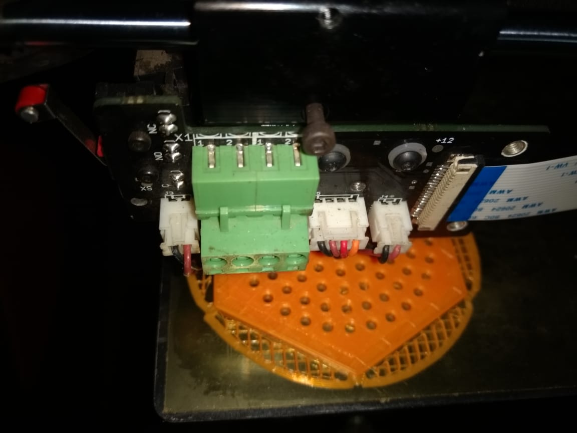
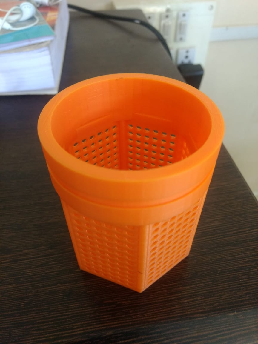
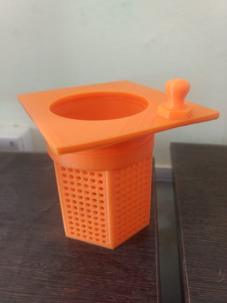
Chamber 1:
At the chamber, students usually throw the left over water remained after deeping plates. The food particles that their in the water gets flow along with that water hence we need to fix a filter which can restrict the flow of food particle along with water. Someone from DBRT (Diploma In Basic Rural Technology) student put a mesh over the chamber but as the water require more time to strain through it, students usually throws water by removing the mesh. So I thought that let’s fit one permanent MS punched mesh over the chamber and one removable mesh over fixed one. Hence one can clean the removable mesh by removing it outside and fixed punched mesh will not allow the food particles pass through it.


Chamber 2:
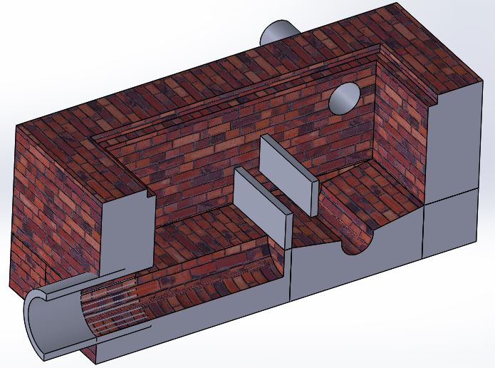
The sewage water from chamber 1 subsequently flows to chamber 2. Main objectives of chamber 2 is to remove oily layer from the sewage water. If we didn’t removed the oily layer, it then restrict all the microbiological processes, hence its very important to remove oil from the water surface. This chamber is constructed in such way that it can remove oily layer as well as the sludge from sewage water. We want minimum retention time at this tank. If water remains stored in tank for long time, then bacterial growth become anaerobic and water start smelling. The design of Chamber something like:
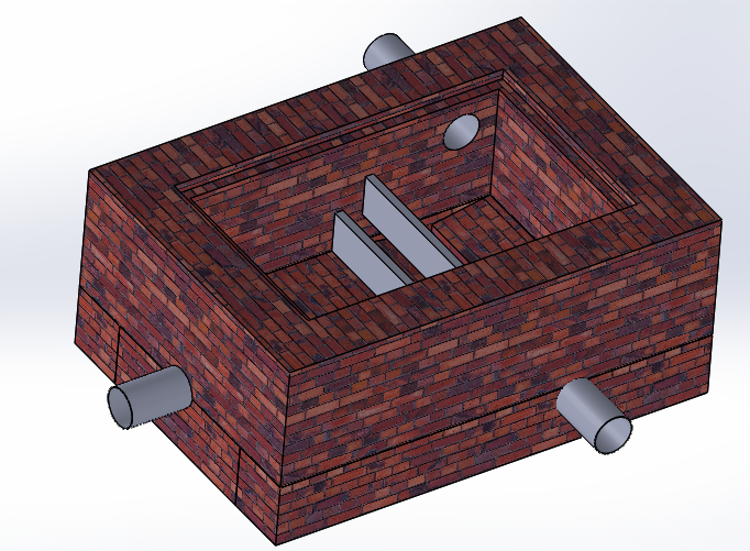
Settler Tank:
The major part of sludge is being settled in the settler tank. Almost 70% of the sludge being settled and drained out in this stage. We finalize our settler tank design after visiting grey water re-circulation system which we seen at the Govardhan Eco-village, Galtare, Wadha. You can find the visit report here
The shape of the bottom of settler tank is little bit V shaped in order to collect it at one place and hence thereafter can be removed easily. There are some vertical and inclined slits are fixed in between the path of water flow is to reduce the velocity of water as well as included particles which forces particles to settle down. At outlet instead of using direct pipe, we joined a T socket their. The T socket allow only water to flow through it and restrict oily layer to discharge with water. The CAD model of settler tank is shown below:


Reed Bed:
The grey water is then pass through the Reed bed for further filtration of small dissolved particles. The reed bed basically consist of three layer in it (each layer is about half feet height). The bottom most layer is of the large sized rocks. Middle layer also consist of stone but these stone are smaller in size as compare to the bottom one. The middle layer us then followed by upper layer made up of sand which is very coarse in size. Upper surface of the sand is then covered by a thin layer of soil which would require for plant to grow up. The grey water from the settler tank is sprayed over the layer of soil in the reed bed. The water is then get percolated/passed through the subsequent layers of the reed bed. The suspended particles are got trapped in the layers of the reed bed. The particles are then being used by the bacteria (as the food) which are there in the soil. The food which is in the complex form got converted to the simple form by the bacteria and as the food is available in the simple form is easily accessible to the plant. Technically says, The grey water which is of high COD (because of high strength food particles in it) got converted to the low COD(Chemical Oxygen Demand) by the means of the bacteria and plants can survive in the low COD, the growth of the plant is initiated. The CAD model of Reed bed is below.
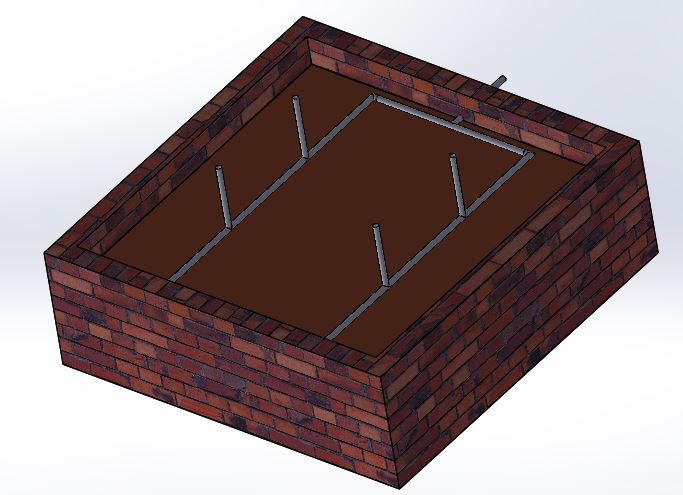

From the Reed Bed, the water is further stored in the tank where aeration manifold is provide. The retention time we provide in this storage tank is 1 day. After 1 day, the water then used for gardening.
Design to Reality:
After designing all the components of the system, we were then started actual construction of Settler tank and then chamner. For construction we appoint some labour from outside. As the labour were not an Engineer, we need to explain our design to them. Somehow we completed the construction of Settler tank and Chamber.


