
What is Grocubator ?
- 30th/Aug/2021
(Growth-Incubator)
It is basically the smart small-medium size incubator for sprouting of 250 gm legumes/seed. It can soak seed as well and recycle same water in entire process. The Grocubator will work on same tranditional steps hence its produce will be completely organic. Intention of this is just to reduce repitative task and effort require for producing buck quantity.The hand behind this setup is Mr. Rahul Kanojia [ Vigyan Ashram Fabacademy ] Blog link – ( http://fabacademy.org/2021/labs/vigyanashram/students/rahul-kanojia/index.html ).
The Grocubator Version 1
“Let food be thy medicine and medicine be thy food”
— Hippocrates
Why you need to add sprouts in your diet ?
- Adding sprouts to your diet can give you the necessary protein intake required by your body minus the fat, cholesterol and calories.
- Sprouts help increase bone formation and prevent them from breakdown or osteoporosis. They are also helpful in controlling hot flashes, menopause, PMS and fibrocystic breast tumours.
- According to experts, sprouts contain 100 times more enzymes than uncooked fruits and vegetables. These enzymes act as catalysts for all your body functions and ensure that your body processes work more efficiently.
- Since sprouts are low in calories, they can contribute positively to any weight-loss diet plan. Eating sprouts will make you feel fuller and stave off hunger longer.
- Once sprouted, the quality and fibre in the beans, nuts, seeds and grains improve. Eating sprouted grains helps you maintain a healthy immune system.
- Research shows that certain sprouts are effective for preventing gastritis, ulcers, stomach cancer and even allergy and asthma.
Article timesofindia.indiatimes.com
Discussion Room :
- 7th- Sept- 2021
The experiencing the existing Grocubator Version 1, we facing some issues while handlling. The discussion on feedback of user & regarding actual problem with grocubator and further directions of designing & scaling the project with engineering considerations, for the requirement of Vigyan Ashram kitchen.
Identified issues with Grocubator V1
- Unpleasant odour of water.
- Noise / irritating sound.
- Cleaning & maintenances issues.
- Duration of sprouting.
- Improper loading and unloading.
Objectives :
- 9th- Sept- 2021
So according to identified issues and discussion we define some objectives and directions.
- Solving the issues of unpleasant odour of water, cleaning and maintenances issues, improper loading and unloading, noise / irritating sound. in version 2
- Redesign & scale up the sprouter system for Vigyan Ashram kitchen
.
- Sprouting time of 18 hrs. is cherry on the cake, cover this point in version 3.
- Vigyan Ashram Kitchen requirement for sprouts :
- Ungerminated seed – 2kg for a day
- 11th- Sept- 2021
Define : Design 2kg sprouting system for Vigyan Ashram kitchen with engineering consideration and by an eleminating issues with version 1 .
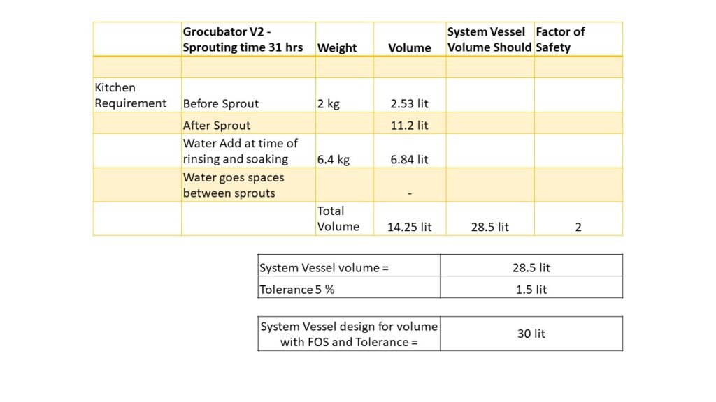
- Calculations for volume check :
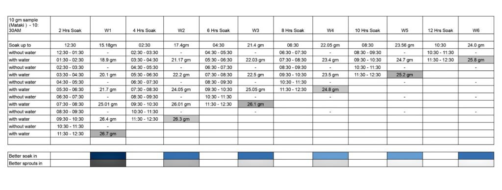
- Experiment for analysis of soaking and sprouting time :
- 13th- Sept.- 2021
- Observation Table :
- 15th- Sept- 2021
- Experiment Graph :
- Graphical Representation of Experimental Data
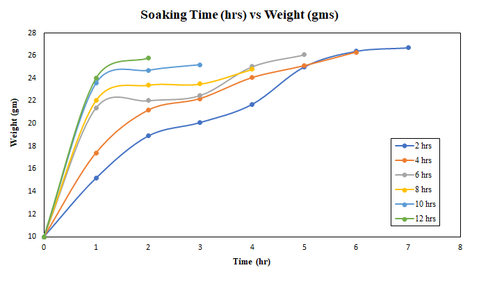
- Interpretation :
- The pre-treated sample of 2hrs, 4hrs,6hrs, 8hrs,10hrs & 12hrs under-go post process of 1 hr. sprouting period ( without water ) and 1 hr. soaking period ( with water ).
- In which 2 hrs. pre-treatment & post process gives better result for sprouts rather than 8 to 12 hrs. of soak pre-treatment
Modified Process Flow :
- 16th/17th – Sept- 2021
According to analysis of above experiment for soaking and sprouting time we togetherly set a system process flow for the project. In that we think about volume and weight of ungerminated seeds, water requirement, soaking period, water aeration time, sprouting time, water circulation, drain system & rinsing etc.
Process Flowchart

System General Layout :
- 18th- Sept- 2021
By the reference of above modified process flowchart we sketch a system General Layout – In that the whole system is mixing of sub system as below :
- Vessel system
- Driving Mechanism
- Water container
- Water pump system
- Aeration system
- So in the whole system the vessel use for holding seeds which should connected to the driving mechanism in order to move the vessel and the water container is connected to vessel in order to collect the drain water form vessel. The aeration is required for water container so aeration system and water pump is connected to water container, with that for pumping the water in vessel we have to connect water pump to the vessel again.

Sub – System Designing :
- 20th- Sept- 2021
- For designing the above 5 sub-system, we need to set priorities for design according to their system functionality.
- Vessel System > Driving System > Water Container > Water Pump System > Aeration system
- Vessel System Design
- For the design of vessel we have to consider parameters for design. For that we have three options for shape of vessel, i.e Cylinder, Hexagonal prism and Octagonal prism.
- Before that collaboratively we have to fix the suitable material for the vessel according to design consideration and shape of vessel. The available possible food graded materials are :
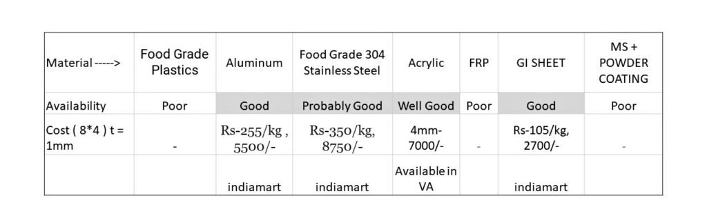
- 21st- Sept- 2021
- To select a suitable shape we consider some design consideration and map the system with that parameters. For vessel system with aluminium material we fix some generalized design consideration as complexity, easy of fabrication, easy of operation, economy, suitability, user friendly & mixing.
| Shape | Surface area to the given Volm | Volume | Material | Availability | Complexity | Easy of Fabrication | Easy of operation | Economy | Sutability | User Friendly | Mixing | Factor |
| Cylindrical | 5405.11016 cm2 | 30 lit | Aluminium alloy | Well Good | 4 | 2 | 5 | 5 | 3 | 5 | 3 | 27 |
| Octagonal prism | 5508.88348 cm2 | 30 lit | Aluminium alloy | Well Good | 5 | 4 | 5 | 4 | 5 | 4 | 5 | 32 |
| Hexagonal prism | 5581.68805 cm2 | 30 lit | Aluminium alloy | Well Good | 4 | 4 | 4 | 3 | 4 | 3 | 4 | 26 |
- 22nd- Sept- 2021 : ( Discussion Room )
- As according to the discussion the octagonal prism is easy to fabricate with minimum complexity and also minimum surface area to the given volume. The octagonal shape is sutable for well mixing of internal material and user friendly to operate. So by the discussion combined factor for octagonal prism is greater than cylindrical and hexagonal prism by the view of design parameters. So we lastly zero down to Octagonal prism with Aluminium Alloy material.
- Volume Calculation for Octagonal Prism :
- Vessel Volume : 30 lit
- Length of vessel : 500 mm
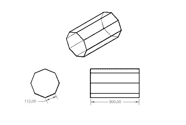
- V=2(1+√2)r^2h
- V= Volume = 30000 cm3
- r = length of side = ?
- L = Length of vessel = 50 cm
- By calculation :
- r = 112 mm
- Take r= 115mm ……….clearence
- 23rd- Sept- 2021
- Shaft Design Calculations :
- Load calculation : As considering maximum static load, the load on shaft is the total weight of sprouts, total water and system load. By the calculation the total maximum load is 23 kg. i.e design a shaft which should sustain 23 kg max load and not to undergo any stress or bending phenomenons.
- design a shaft for static load, shaft material = 304 stainless steel.
- permissible/allowable stress for shaft material is T=140 MPa
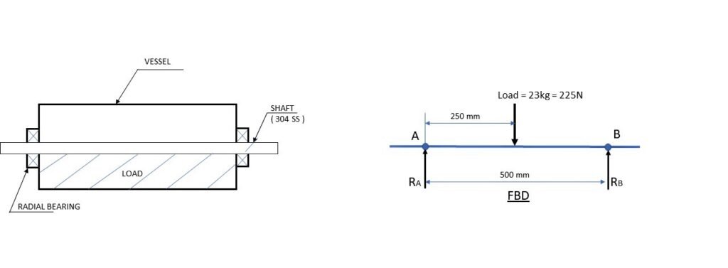
In above free body diagram Ra and Rb are reaction at bearing A and bearing B respectively.
⸫ Ra + Rb = 225 N
⸫ M@A = 0 => ( 225 * 250 ) – ( Rb * 500 ) = 0
⸫ Rb = 112.5 N & Ra = 112.5 N
Calculate the bending moment : as BM@A = 0 and BM@B = 0
⸫ BM@C = 225 * 250 = 28050 N.mm
⸫ The maximum bending moment is at point C , i.e = 28050 N.mm
- Maximum bending stress ( Tb ) = ( M*r ) / I
- M= Max bending moment on shaft = 28050 N.mm
- r = Radius of shaft.
- I = Moment of Inertia of shaft = ( π r^4 ) / 4
- ⸫ I = 0.785r^4
Replace maximum bending stress with the given allowable stress for the shaft material.
⸫ τ allowable = ( M*r ) / I
⸫ τ allowable = ( M*r) / 0.785r^4
⸫ τ allowable = ( M ) / 0.785r^3
⸫ 140 N/mm2 = ( 28050 ) / ( 0.785 * r^3 )
⸫ r = 6.35 mm & Dshaft = 12.68 mm
considering FOS as 1.5 to 1.7
i.e Design a shaft of minimum 22 mm in diameter.
- 25-27 th- Sept- 2021
- Standard Bearing Selection :
- as select the bearing according to load condition, in our system the load mostly radial ( ⊥ to shaft ) so use radial bearing.
- Radial bearing has two types :
- Radial ball bearing
- Radial roller bearing
- According to the minimum shaft diameter we have to select the bearing : from the data book size chart for radial ball bearing we select : 6906 radial ball bearing :
- Bore diameter (B) = 25mm
- Outer diameter ( OD ) = 42 mm
- Width ( W ) = 9mm
- Ball size = 13-3/16 , r=0.5mm
So according to bearing bore diameter we have to select the shaft diameter ( Dshaft = 25mm ).
- Torque Calculation :
- Find the torque required to rotate the vessle system. For that the total load of system = 23 Kg and shaft weight = 3 Kg , so total weight of system is 26 Kg.
- Formula to find out the torque : τ = Mass Moment of Inertia ( I ) * Angular Accleration ( α ) .
⸫ Find out Angular Accleration ( α ) = 2π * Nmax / 60t …………………………………………………….Nmax = 20rpm
⸫ Angular Accleration ( α ) = 2.0946 rad/s
- Now calculate the moment of inertia for octagonal prism :
- ⸫ MMI for Octagonal Prism = (MR^2)/2[1-(2〖sin〗^2 (π/8))/3]
- M = weight of system = 26 kg
- R = r / 2sin(π/8) ………………………r = side of octagon
- R = 112 / 2sin(π/8) = 90.39
- ⸫ MMI for Octagonal Prism = [ ( 26 / 2) * (90.39)^2 ] * [1-(2〖sin〗^2 (π/8))/3]
- ⸫ MMI for Octagonal Prism = 1062.11 kg-cm2
- ⸫ Torque ( τ ) = ( 1162.11 * 2.0946 )
- ⸫ Torque ( τ ) = 2224.69 kg-cm2/s2 = 22.2469 N-cm
- ⸫ Torque ( τ ) = 2.268 kg-cm
There for the minimum torque required to rotate the system is 2.268 kg-cm.
For system we consider FOS = 2.2 to 2.5 .. i.e design a driving system in static condition for MAX torque= 5 to 6 kg-cm
- 28th- Sept- 2021
- Driving System Design
- Driving Mechanism : Mainly 2 types of drive system are –
- Direct drive mechanism :
- Indirect drive mechanism:
- Benifits of direct drive mechanism over indirect drive mechanism :
- Direct drive avoid most mechanical transmission elements.
- Higher system rigidity of direct drive allows extreamly precise positioning, high accleration at much shorter cycle time.
- Direct drive system are characterized by smooth torque transmission.
- Direct drive increased efficiency due to reduced power losses through mechanical transmission.
- 1st-Oct- 2021
- Mouth Opening of Vessel :
- The design of mouth of vessel is should me more user friendly to open and close.
- The design of mouth of vessle should be easy to fabricate and operable.
- The design of mouth of vessle should be not have complexity.
- The design of mouth of vessle should be easy or convenient to wash the vessel.
- If we open a vessel from side –
- If we open a vessel from side it is difficult to add or remove sprouts to the vessel or from the vessel.
- As the one side of vessel is attached to drive system and second have bearing so opening form bearing the door/mouth not easy to fabricate.
- If we open a vessel from the length – ( Half portion of vessel )
- It have large opening to add or remove the sprouts.
- easy for the attachment and fabrication.
- one hand opening and user friendly to wash as opening area is more.
- By the above two option if we open the vessel from the length ( half portion of vessel ) can give more user friendly operation and easy of fabrication, so we select the 2nd option that mouth opening of vessel is form length of vessel ( Half portion of vessel. )
- Till Now Zero Down Points for Vessel :
- Shape – Octagonal.
- Material – Aluminium Alloy sheet.
- Rotating axis – Central axis.
- Dimension of vessel –
- Volume ( V ) – 30 lit
- Base edge ( r ) – 115mm
- Length ( L ) – 500 mm
- Mouth opening – From Length
- Central axis shaft –
- Material – 304 SS
- Diameter – 25 mm
- Bearing type – Radial ball bearing
- Bearing No– 6906
- Bore diameter (B) = 25mm
- Outer diameter ( OD ) = 42 mm
- Width ( W ) = 9mm
- Hand Sketch For Vessel :
- 4th Oct 2021
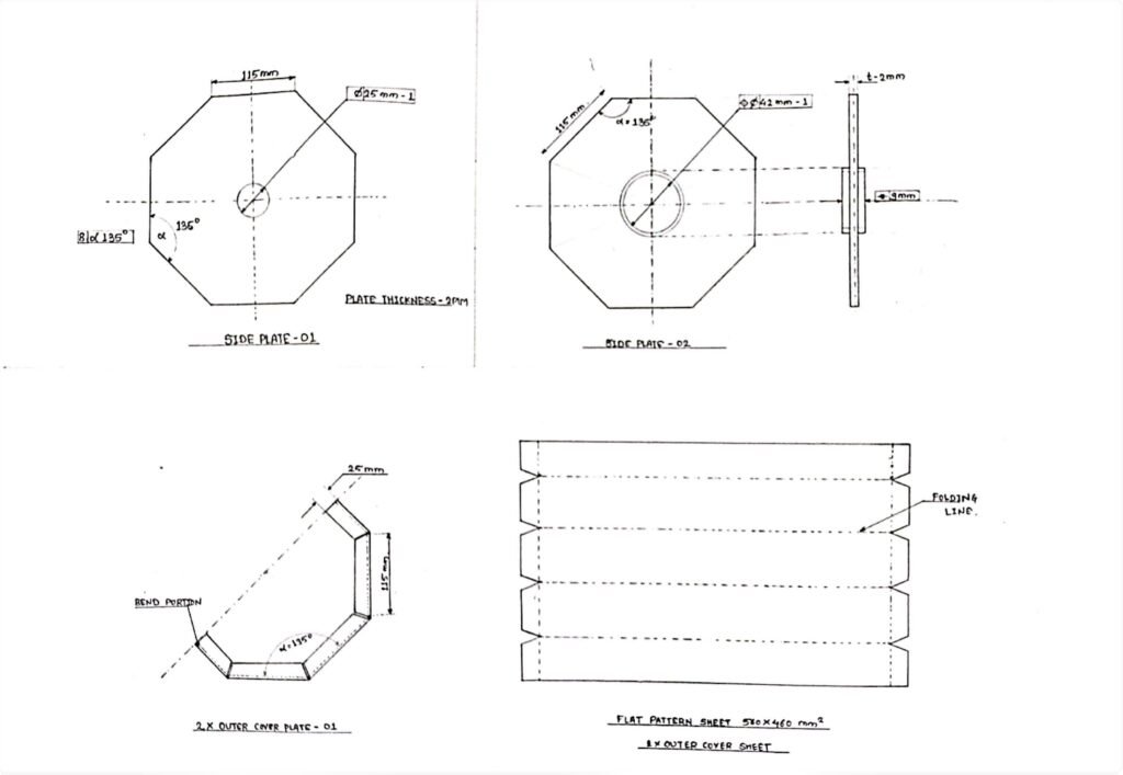
- Part List for vessel :
- Side plate 01 – Octagonal shape ( @driving system )
- Aluminium A sheet 2mm Thickness
- Side plate 02 – Octagonal shape ( @bearing attachment )
- Aluminium A sheet 2mm Thickness
- Outer cover plate ( 560 * 460 mm2 )
- Aluminium A sheet 2mm Thickness
- Side plate 01 – Octagonal shape ( @driving system )
- Hand sketch for two side plate and outer cover sheet :
- Solid works CAD Modelling for Vessel :
- 4th-Oct-2021
- CAD modelling in solid-works ( sheet metal )
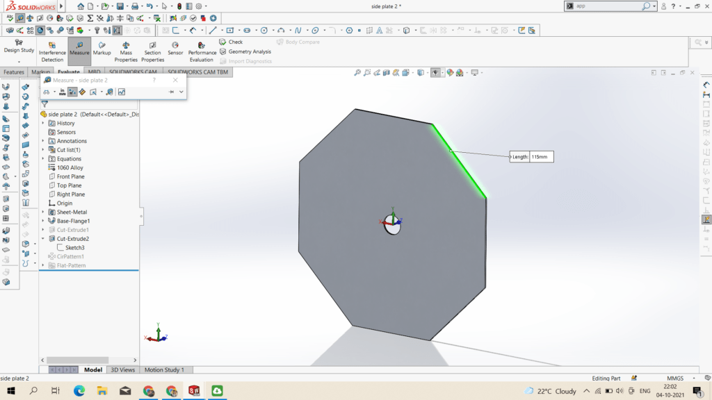
SIDE PLATE – 01 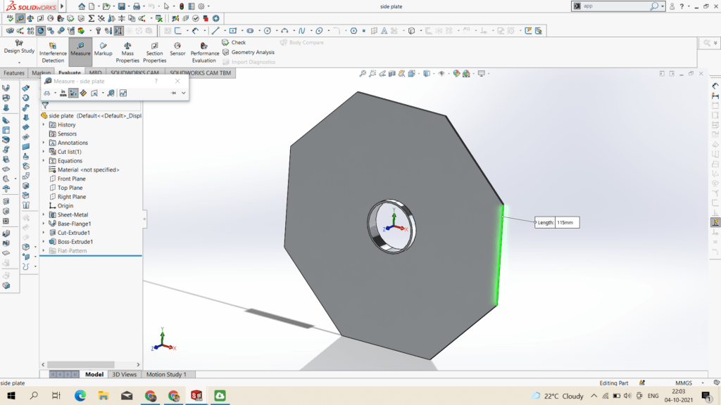
SIDE PLATE – 02 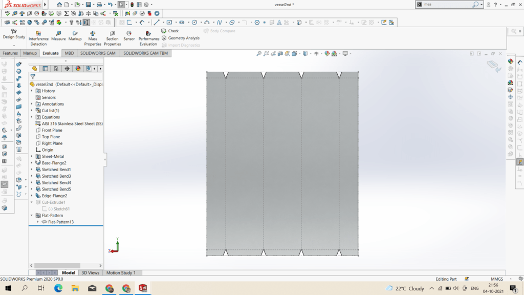
PLAT PATTERN OUTER COVER SHEET 560 * 460 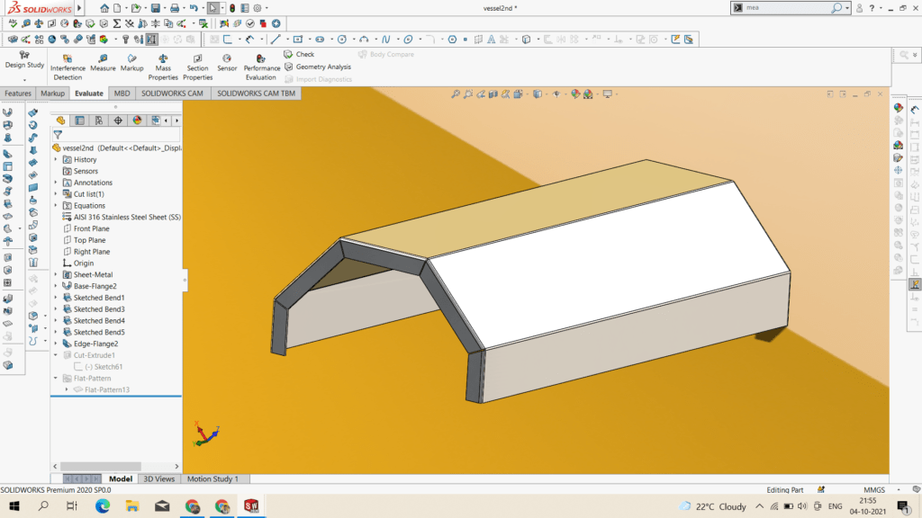
BEND – OUTER COVER SHEET * 2
- 5th-Oct-2021
Discussion Room : New Idea
- As we passing through ideation phase many new ideas come into the brain, which seems to be more efficient than existing idea so we have to think by quantify approch towards new idea that it is sutable or not.
- As above while designing drive system we think of two types of drive first is rotating through center of axis and second is rotating through other than central axis.
- So if we change the central axis drive system and implement the roller based drive system on which the vessel will rotate, which gives user friendly operation for add / removal of vessel from the system.
- Roller based drive system :
- In roller based drive system, the roller profile is circular so the vessel profile should be circular as vessel will rotate on the roller.
- General layout for roller based drive system :
- Vessel shape : Cylindrical vessel
- Vessel volume : 30 lit
- Vessel size :
- Material : Market Availability
- Poly-propylene (PP)
- HDPE
- Aluminium alloy
- Design the roller :
- 6th-Oct-2021
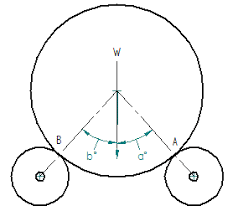
- Force analysis for roller system :

- In static – ( Ra = Rb )
⸫ 2 Ra*sin45° = 250 N
⸫ Ra = Rb = 176.77 N ~= 180 N
- Calculation for Bending moment and shaft diameter :
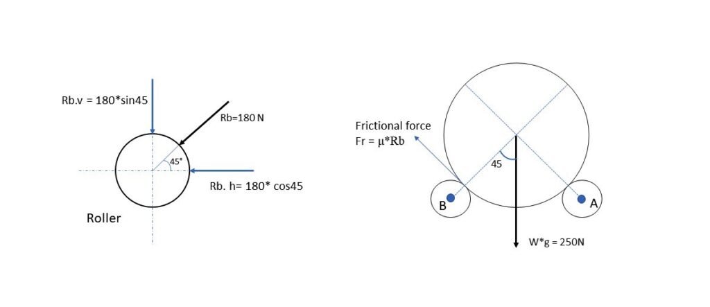
- Vertical bending moment : BM@V = 180*sin45 * 250 = 16000 N.mm
- Horizontal bending moment : BM@V = 180*cos45 * 250 = 16000 N.mm
- BMmax = √BMh^2 + BMv^2 = 22627.41 N.mm
⸫ τ max = (16/ πd^3 ) * BMmax
⸫ 110 Mpa = (16/ πd^3 ) * 22627.41
⸫ d =~ 11 mm
As FOS is 2 to 2.5 we have to take diameter of roller is 22 to 25 mm with SS 304 material shaft.
————————————————-
- 8th-Oct-2021
- Calculation for Torque requirement – due to friction force:
- Frictional force ( Fr ) = μ*Rb ………………………………………………( μ = 0.25 ).
- ⸫ Fr = 2μ*Rb ……………………………………….For 2 roller.
- ⸫ Fr = 2*0.25*180 = 90 N
- Torque = Fr * Radius of roller ( cm )
- ⸫ Torque = 90 * 1.75 N-cm
- ⸫ Torque = 157.5 N-cm
- ⸫ Torque = 15.25 kg-cm
- Calculation for Torque requirement – for vessel :
⸫ Find out Angular Accleration ( α ) = 2π * Nmax / 60t …………………………………………………….Nmax = 20rpm
⸫ Angular Accleration ( α ) = 2.0946 rad/s
⸫ MMI of circular vessel = (25*15^2)/2 = 2812.5 kg-cm2
⸫ Torque = 2812.5*2.0946 = 5891.06 = 58.91 N-cm
⸫ Torque = 5.891 kg-cm
⸫ Total Torque = 15.25 kg-cm + 5.891 kg-cm = 21.14 kg-cm
- 10th-Oct-2021
- Vessel Selection : Round / Cylindrical shape
- In ideation-brainstroming session we think about market availability and material selection. The aluminium alloy vessel ( Aluminium Dabba ) is more sutable according to market availability, material availability, sutability, cost efficient and easy for operation and fabrication.
- Design and sketching of Vessel and roller :
- Roller material – PP
- Vessel Material – Aluminium alloy.
- For restrict the transverse motion of vessel we use a gripper belt.
- Hand sketches :

- 12th to 18th -Oct-2021
- CAD Modelling for Vessel and Roller system :
- By using solidworks we create a CAD model.
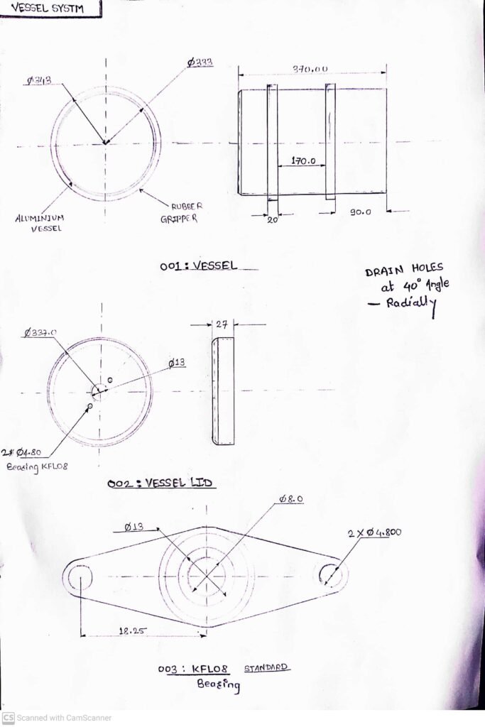
- Parts List :
- Vessel system :
- Aluminium Vessel and Lid
- Gripper Belt
- KFL08 Bearing for lid
- Roller system :
- Roller – PP
- Shaft – MS
- Pedestal Bearing KP002 / 15MM
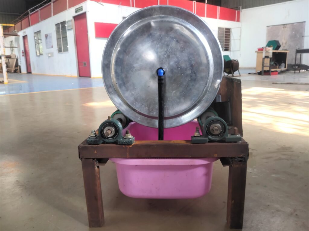
- Vessel system :
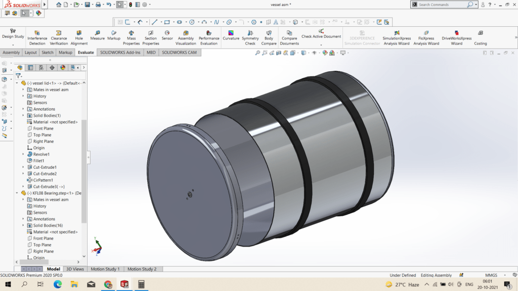
Vessel CAD 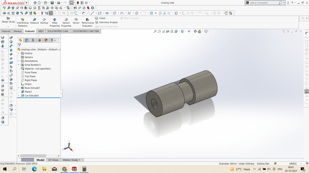
Roller CAD 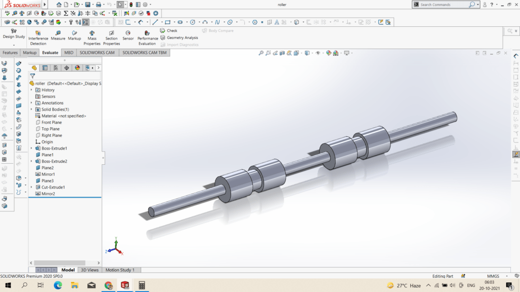
Roller Shaft CAD 
Bearing & Roller Assembly 
FV- Vessel Roller Assembly 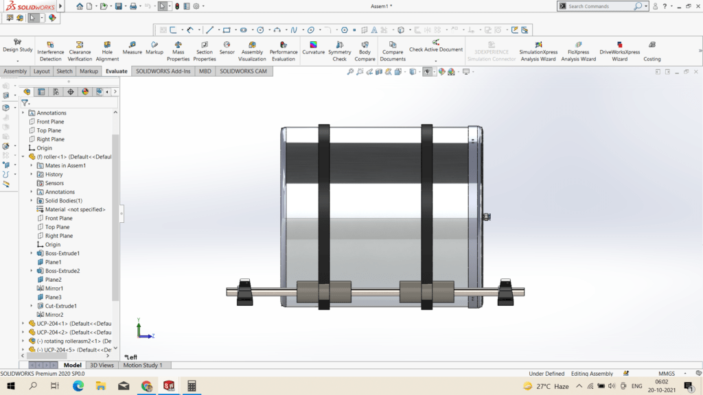
SV – Vessel Roller Assembly

The assembly of vessel which rotate on roller- in that one roller system is attached to drive and another roller system is idler. The distance between two roller system is maintain that vessel to roller central angle is greater than 40 to upto 45 ,so that vessel should rotate between the roller system.
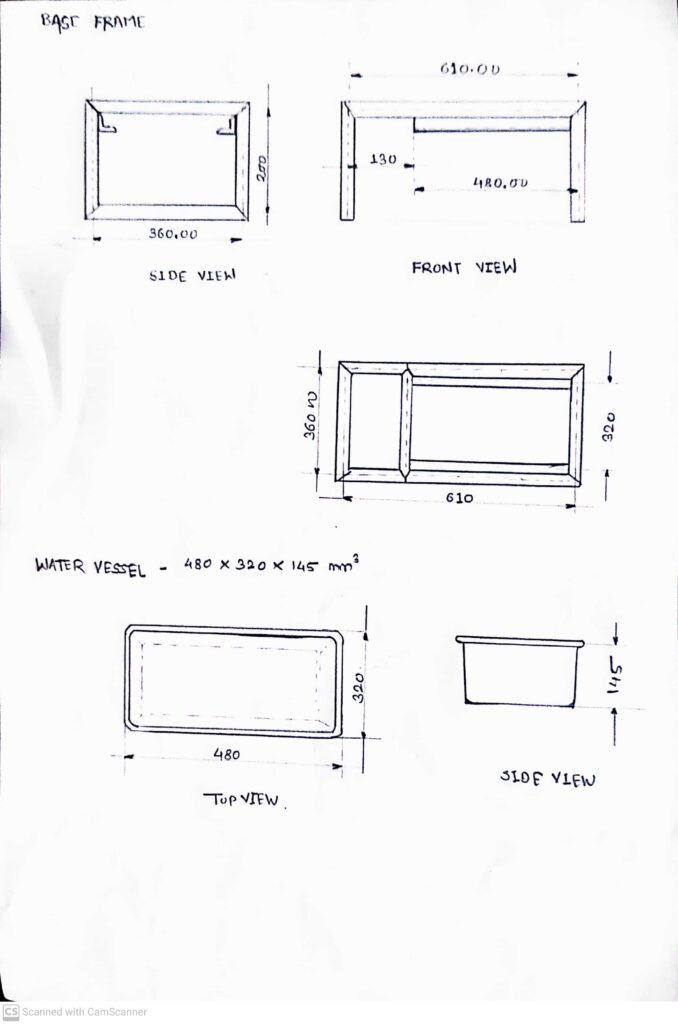
- Water Container & Base Frame Design :
- 19th – 20th -Oct-2021
Water container hold the water which come from drain holes of vessels, while designing water container we have to consider design parameter or design consideration according to vessel design and aeration system.
- Design and Sketching of base frame and Water Container :
- Part List :
- Base Frame/Fixture :
- Square Tube – 40*40*2 mm – MS
- L angle – 25*25*2 – MS
- Sheet – 4*2 FT*1mm – MS
- Water Container :
- Base Frame/Fixture :
- Hand Sketches :
- Part List :
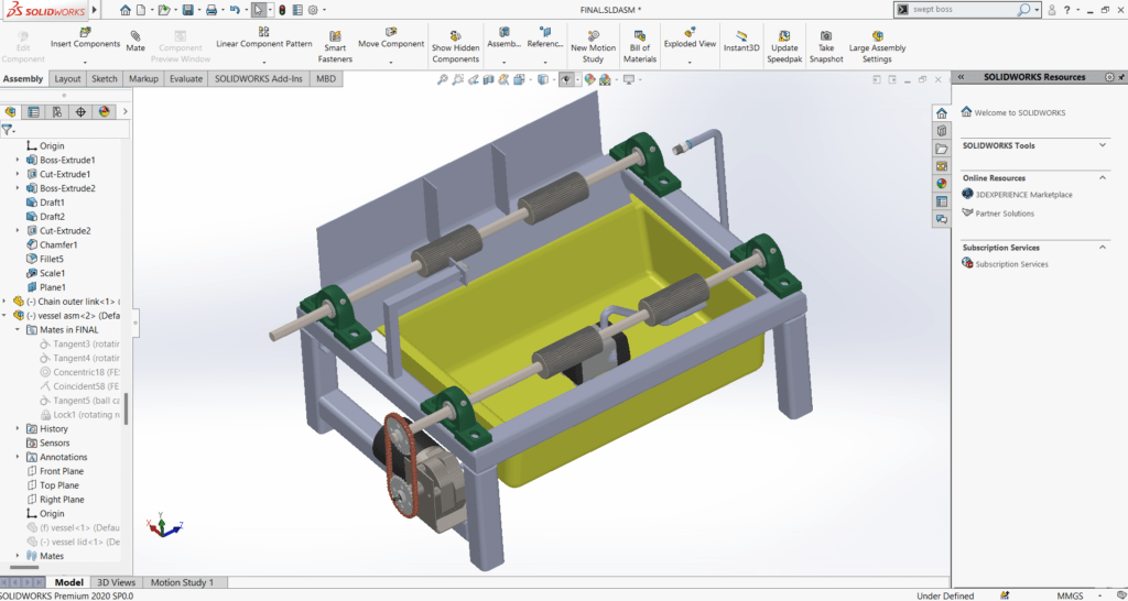
- CAD Modelling for Base frame and Water Container :
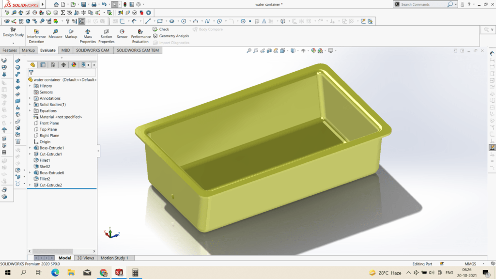
Vessel 
Base Frame 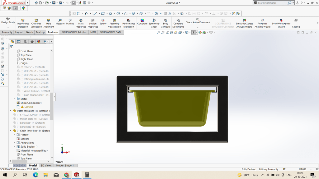
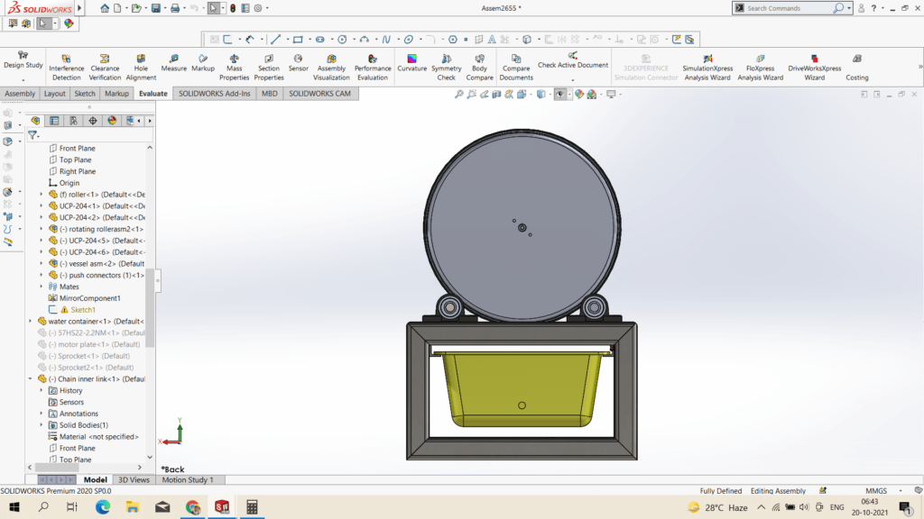
Assembly Side View 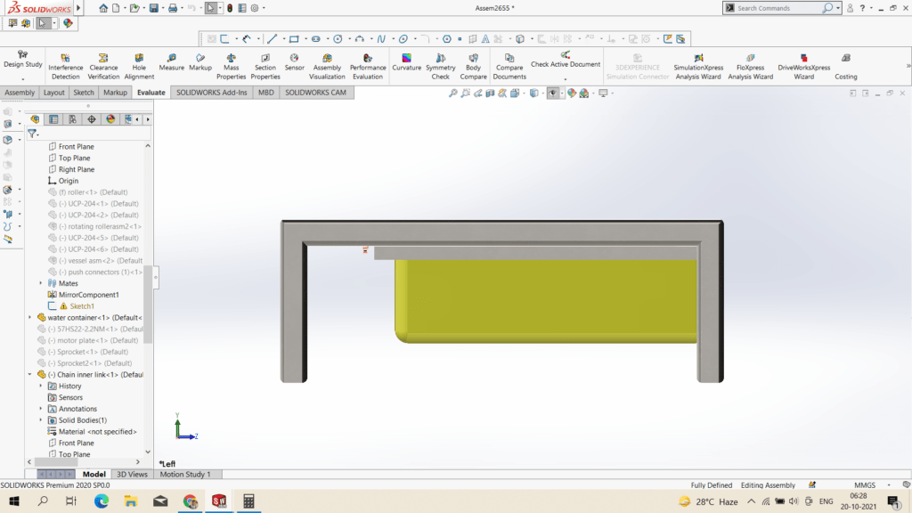
Assembly Front View 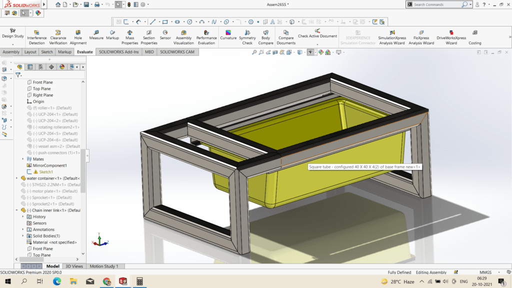
Assembly Design Isometric
- Updated on – 21th -Oct-2021
- Assembly for Roller vessel system and Base frame system :
Assembly Side View 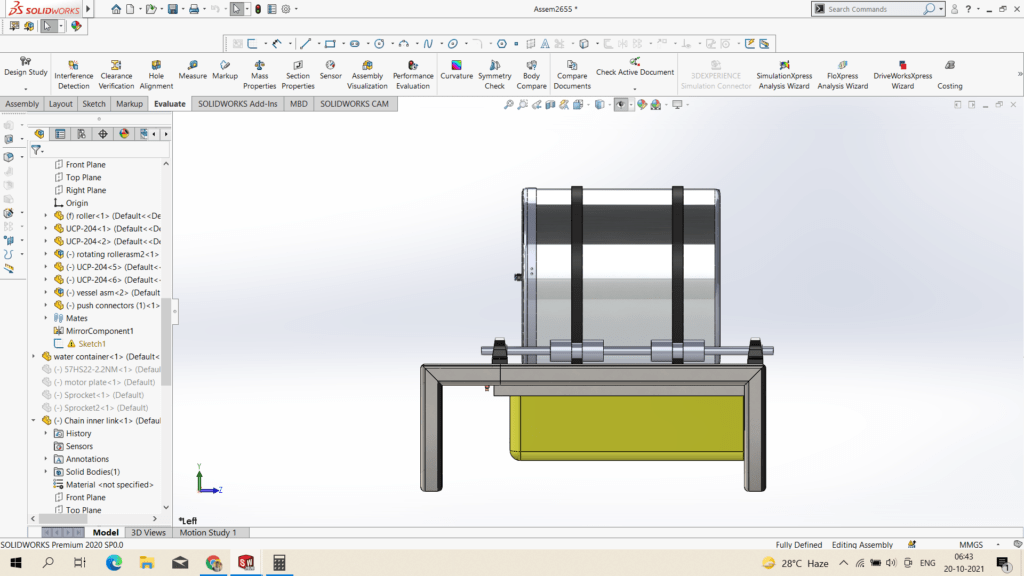
Assembly Front view 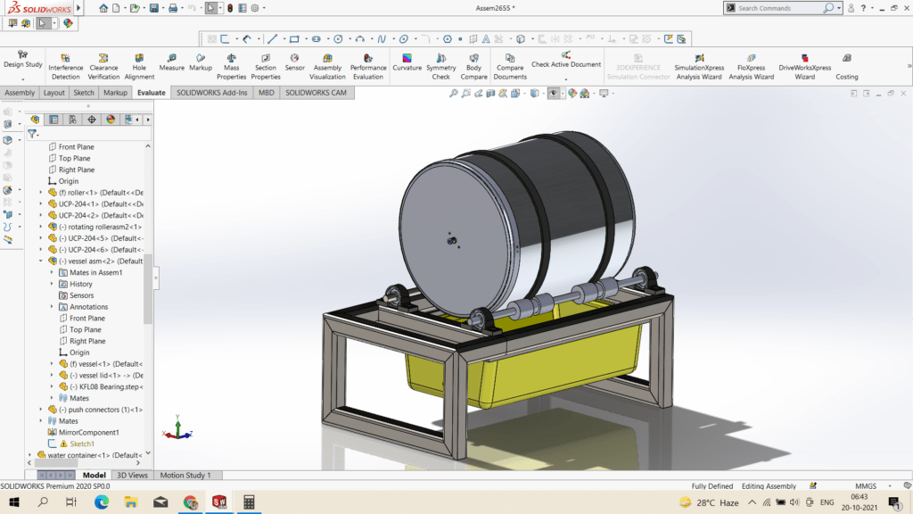
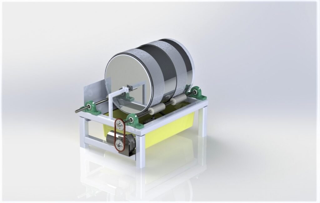
Assembly – Rollers System + Vessel System + Water container and fixture/base frame
- Driving system :
- Wiper Motor
- Arduino
- Relay 2 Chhanal
Market Survey & Bill of Material ( BOM ) :
- Updated on – 21st – Oct- 2021
- Submitted the tentative Bill of Material for project, discuss with Mr. Prasad Patil and Mr. Prathamesh Darwade sir regarding correction and update in BOM.
- Quotation has passed on 22nd-Oct-2021.
- Procurement process started from 22nd Oct and upto 29th Oct ( Tentative ) all material will procuring.
- Parallelly Fabrication will start form 25th Oct 2021.
- Updated on – 19th- Nov- 2021
- Fabrication :
- Base Frame : Material – MS Tube ( 40X40X2.5 ) cm
- Operations :
- MS tube Cutting
- Welding
- Operations :
- Updated on – 21th- Nov- 2021
- Roller Systems : Material – MS shaft ( Dia-16mm )
- Operations :
- Turning for MS shaft
- Cutting of PP Roller
- Drilling of PP Roller
- Fixing PP Roller to shaft
- Mounting Roller system on Base Frame.
- Operations :
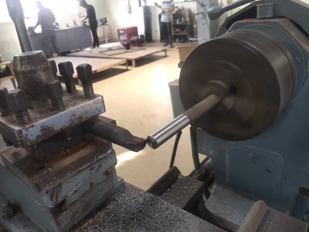
Lathe Turning 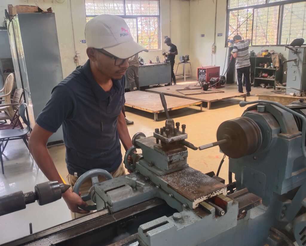
4 Shaft turn up to 12mm – Used for Bearings 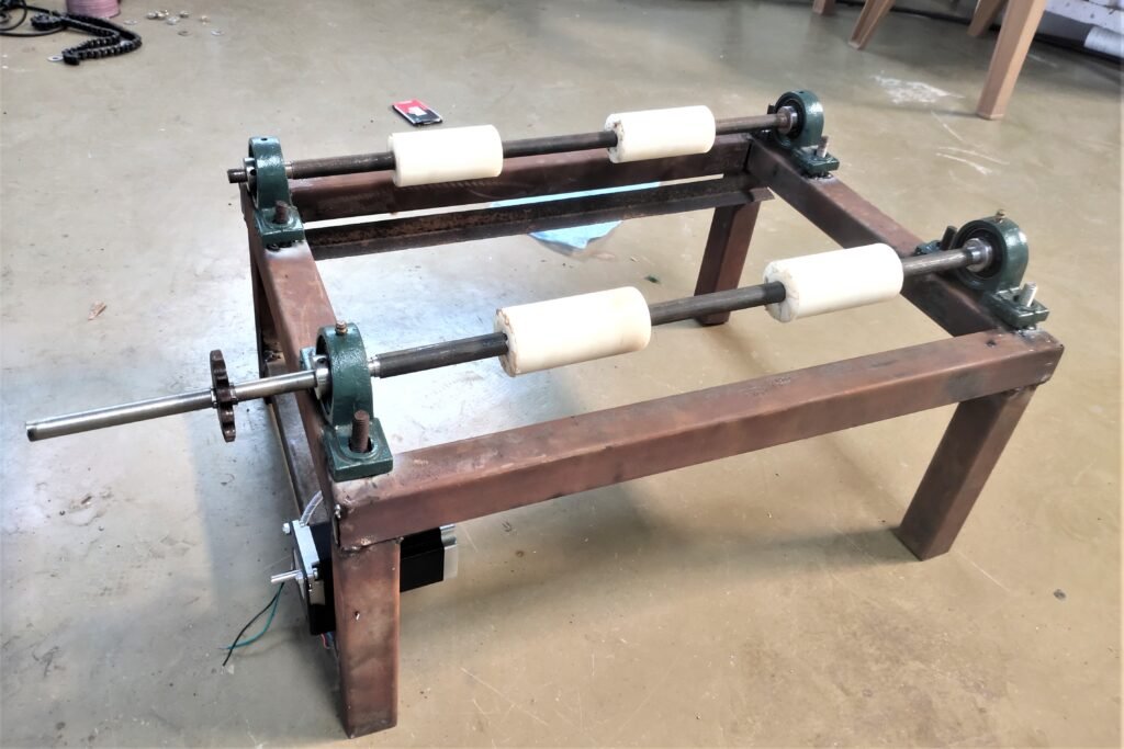
Mounting of Rollar system with base frame
- Updated on – 28th- Nov- 2021
- Driving System and Transmission :
- Issue with Stepper Motor – We try to rotate the roller with stepper motor but due extra load the motor not able to rotate ….may be the issue in current requirement.
- We change the motor and now we try it with wiper motor.
- In transmission we used sprocket and chain mechanism to rotate the rollar.

- In this system both surfaces are smooth and slippage occours.
- To reduce the slippage we use rubbers arrangement.
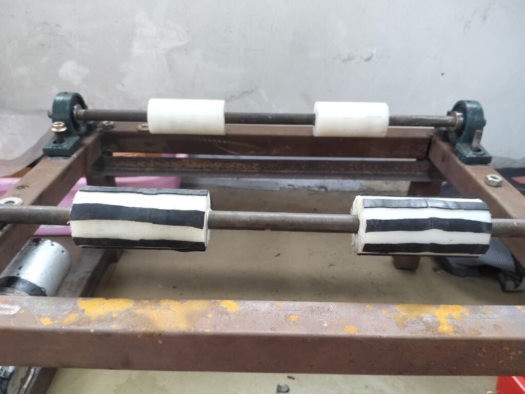

- Now after rotating we observed that slippage are comapratively less than existing.
- Problem while using this rubber :
- There is uneven gap between two rubbers, so no proper mating with rollers rubbers.
- The adhesion between rubbers and steel is not effective, rubbers remove while rotating.
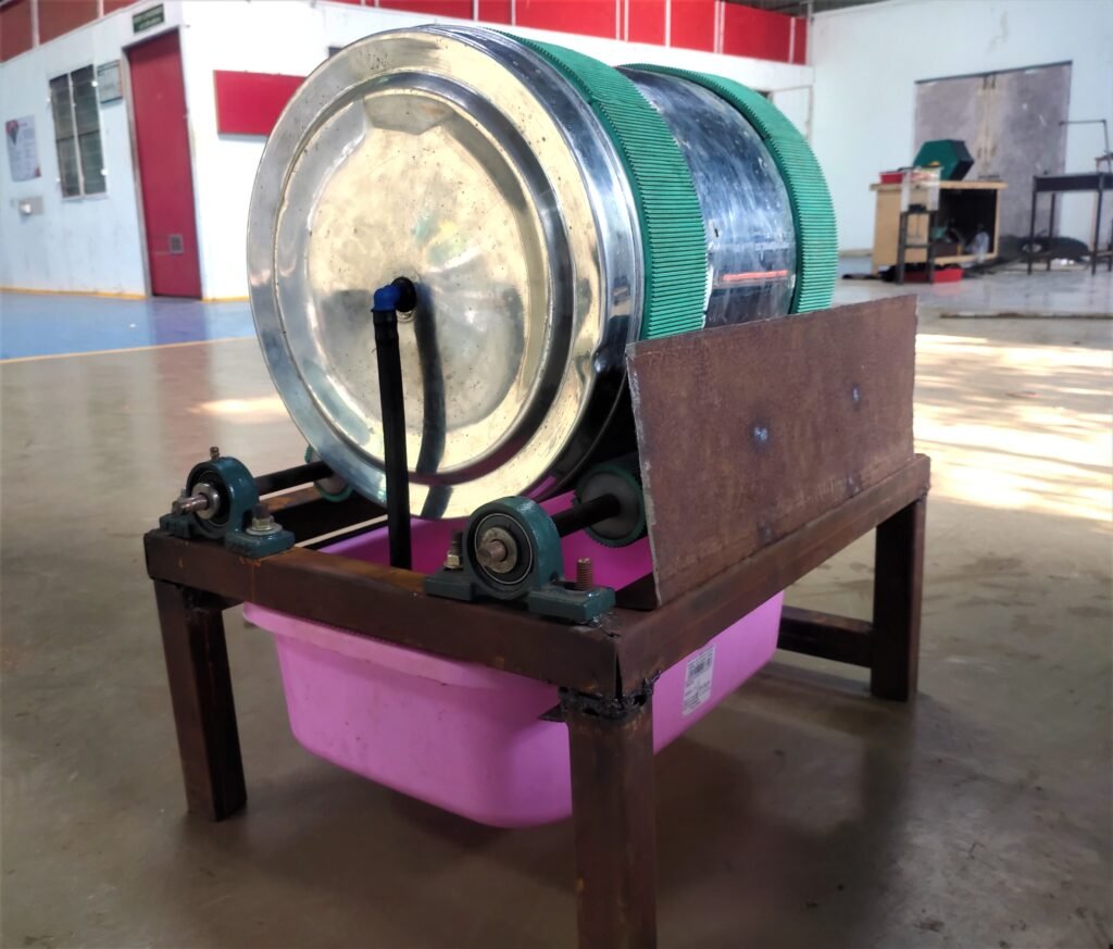
- Updated on – 2nd- Dec- 2021
- We have to use evenly distributed gaps rubber (i.e. Timing Belt Type ) on both vessel and roller. We use superglue as adhesion for attachment of vessel and rubber.
- This solution worked very effectively, no slippage is observed & rotation is also smooth.
- Problem Identified that along with rotational motion their is a transvers motion observed. To overcome a tranverse motion we have to provide a guide.
- Vessel Drainage holes :
- Hole size for drainage holes should be less than the minimum size of grain ( Mataki ). Here we use a mesh from inner side and 3mm holes on vessel.
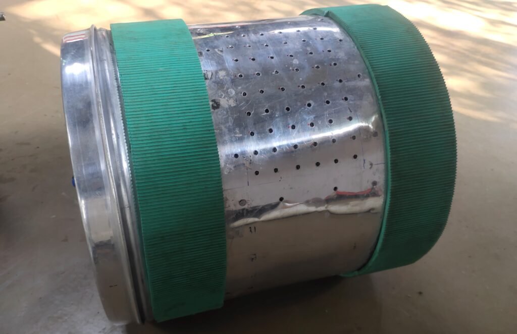
- Vessel Drainage holes :
- Hole size for drainage holes should be less than the minimum size of grain ( Mataki ). Here we use a mesh from inner side and 3mm holes on vessel.
- The mesh attached in inner side of vessel and the side of mesh filled with silicon to reduce extra leakage from side of mesh.
- Water Pump system :
- Rough Testing 1 : To check water pump system and drainage system :
- We observed that – No water leakage at vessel lid & Pump work smoothly.
- Problem identified – that while rotating the vessel filled with water, due to gravitational potential water comes out of the envelope.
- To overcome this problem we add a guide/baffled to restrict the water on one side of system.
SIDE VIEW 1 
FRONT VIEW 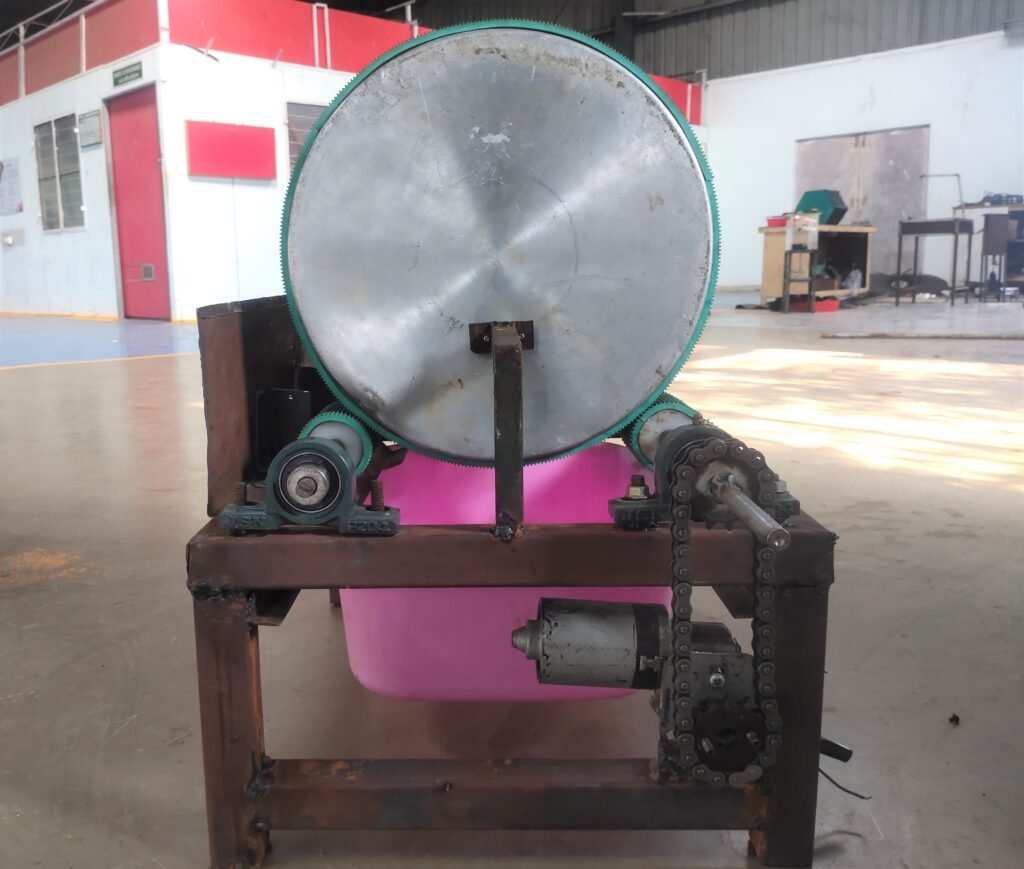
SIDE VIEW 2
- Updated on – 31st -Dec-2021
- Baffled Positioning & Attachment :
- We have to design a baffled shape in such a way that the water which come out of envelope should diverge into the water container.
- The position and attachment of baffled also should be in the envelope of system.
- In 3 to 4 trial we observed that now their is no water falled out of the envelope, it is completely going inside the water container due to baffled system.
- Updated / Refined BOM – Part Listed
| Sr.No | Components | Specification | Qty |
| 1 | Base Frame | ||
| 1.1 | MS Sq Tube | 40*40*2 | 1 |
| 1.2 | MS Sheet | 1.5 mm | 1 |
| 1.3 | L angle | L = 5ft, 20*20 | 1 |
| 2 | Water System | ||
| 2.1 | Water Container | (48*34*14.5) 15lit | 1 |
| 2.2 | Water Pump | 18 Watt | 1 |
| 2.3 | Water Tube | 16mm | 1 |
| 2.4 | Push Connector | 10mm | 1 |
| 3 | Driving System | ||
| 3.1 | Wiper Motor | 12V DC | 1 |
| 3.2 | Sprocket | _ | 2 |
| 3.3 | Chain | _ | 1 |
| 4 | Roller System | ||
| 4.1 | Nylon Roller | Dia-40mm, L=100mm | 4 |
| 4.2 | MS Bar | 12mm/6feet | 1 |
| 4.3 | Bearing | UPC204 | 4 |
| 5 | Vessel System | ||
| 5.1 | Aluminium Dabba | 34.5cm Dia | 1 |
| 5.2 | Timing Belt | W=100mm, L=2.5ft | 1 |
| 5.3 | Fine Mesh | 0.5*0.5ft | 1 |
| 6 | Control/Electronic System | ||
| 6.1 | Arduino uno | _ | 1 |
| 6.2 | 2 Channal Realy | 5V | 1 |
| 6.3 | Jumper/connection wire | 10 | |
| 6.4 | SMPS Powe Supply | 12 V DC , 10Amp | 1 |
- Refined CAD Modelling :


CAD file 
CAD File
- Final CAD – Rendered File :
- Updated on – 3rd -Jan -2022
- Calculation of Time delay for process :
- Water filling time delay :
- Total water in container – 14 lit
- We pump 8 lit of water in 150 sec.
- 180 degree Rotation up time delay : 5.60 sec.
- 180 degree Rotation down time delay : 5.25 sec.
- Water drain time delay : 180 sec.
- Water filling time delay :
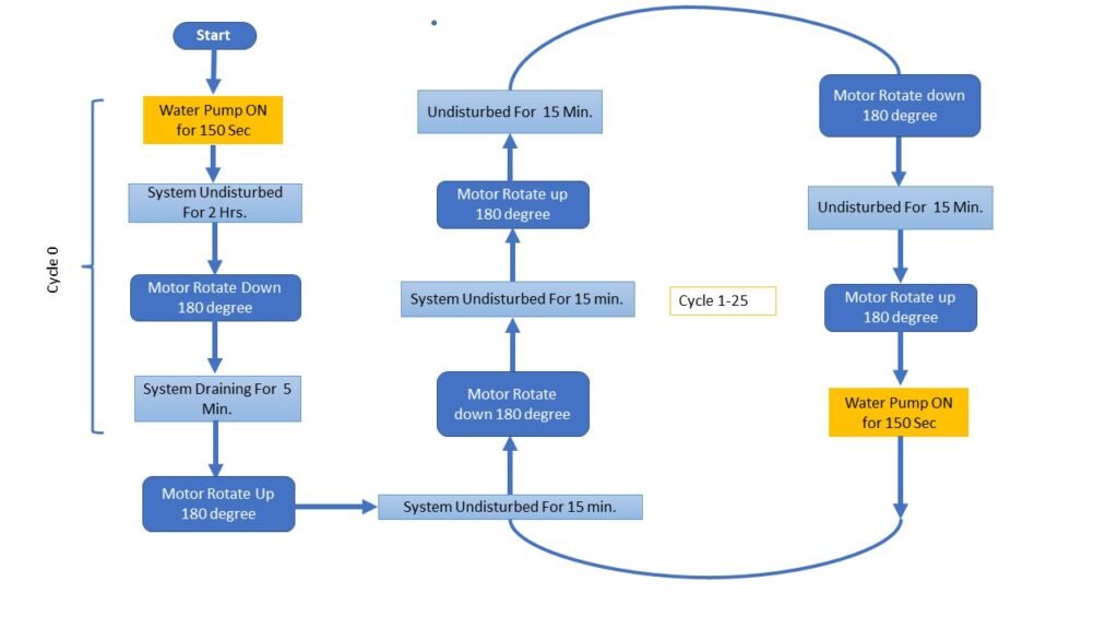
- In discussion – We again discussed about process flow of system based on the experiments we performed previously for mataki.
- Generally in first process flow, we presoak ( Pretreatment ) for 2 hrs and post process for every 1 hours with and without water.
- As we identify form experiment that grains/seeds consume mazimum water in first 2 hrs, So then we can reduce the post process timing of with water treatment.
- Also we need to wash the seed, replace the water and displace the air between the gaps of seeds which can help the seed to again contact with new air.
- Updated Process Flow :
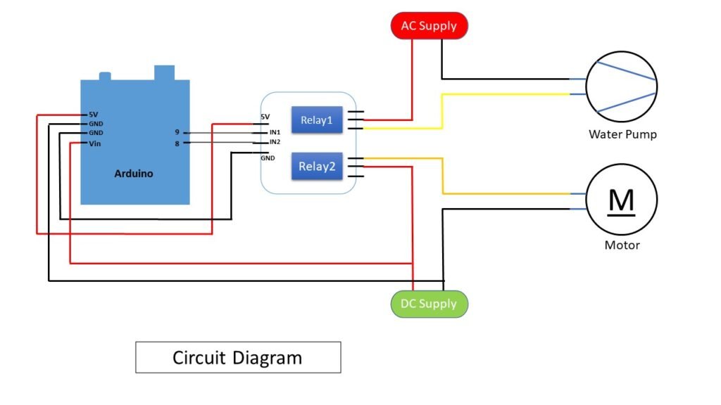
- Circuit Diagram :
- Components :
- Wiper Motor
- 2 Chhanal Relay
- 18W Water Pump
- Arduino
- SMPS Power Suppy – 12V
- Jumper Wires – Connection Pins
- Components :
- Updated on – 8th -Jan -2022
- Program / code<> :
//Grocubator Process Code
//DIC Vigyan Ashram, Pabal

int cycle;
int timer=0;
int water_pump =8;
int motor = 9;


void setup() {

  Serial.begin(9600);

  pinMode(water_pump, OUTPUT);
  pinMode(motor, OUTPUT);


for(cycle = 0; cycle < 1; cycle++)
  {
    Serial.println("Cycle 0 Begin");

   for(timer = 0; timer < 150; timer++) ////  Water Pump ON for 150 seconds
                                                ................................................... Step 1
   {
    digitalWrite(water_pump, LOW);
    digitalWrite(motor, HIGH);
    delay(1000);


    Serial.print("Water Pump ON for ");
    Serial.print(timer);
    Serial.println("  seconds.");


   }

 timer=0;
 digitalWrite(water_pump, HIGH); /////  Water Pump OFF
 Serial.println("PUMP OFF...");


  for(timer = 0; timer < 7200; timer++) //// 2 hours undisturb
                                             ...................................................... Step 2
  {
    delay(1000);

    Serial.print("System Undisturb for  ");
    Serial.print(timer);
    Serial.println("  seconds.");

  }

timer=0;

for(timer = 0;timer < 5; timer++) ///// Rotation motor down of Vessel for 5.5 seconds
                                         ........................................... Step 3
  {


   digitalWrite(motor, LOW);
   delay(1050);

   Serial.print("Motor ON  ");
   Serial.println(timer);

  }

  timer = 0;
  digitalWrite(motor, HIGH);
  Serial.println("Motor OFF...");


for(timer = 0; timer < 300; timer++) ///// Draining time of 5 minutes
                                          ........................................... Step 4
  {

   delay(1000);


   Serial.print("Draining time:  ");
   Serial.print(timer);
   Serial.println(" Seconds.");

  }

  timer = 0;

for(timer = 0;timer < 5; timer++) ///// Rotation up of Vessel for 5.5 seconds
                                         ........................................... Step 5
  {


   digitalWrite(motor, LOW);
   delay(1120);

   Serial.print("Motor ON  ");
   Serial.println(timer);

  }

  timer = 0;
  digitalWrite(motor, HIGH); //// motor STOP:
  Serial.println("Motor OFF...");

  }

for (cycle = 1; cycle < 25 ; cycle++)
{
  Serial.print("Cycle  ");
  Serial.print(cycle);
  Serial.println(" begins");

for(timer = 0;timer < 900; timer++) ///// Undisturb for 15 min
                                       ............................................... Step 6
  {

   delay(1000);

    Serial.print("System Undisturb for  ");
    Serial.print(timer);
    Serial.println("  seconds.");

  }

timer = 0;

   for(timer = 0; timer < 5; timer++) ////  Water motor dowwn for 5 seconds
                                         ................................................... Step 7
    {


   digitalWrite(motor, LOW);
   delay(1050);

   Serial.print("Motor ON  ");
   Serial.println(timer);

  }

  timer = 0;
  digitalWrite(motor, HIGH);
  Serial.println("Motor OFF...");

   for(timer = 0; timer < 900; timer++) ///// Undisturb for 15 min
                                        ............................................... Step 8
  {

   delay(1000);

    Serial.print("System Undisturb for  ");
    Serial.print(timer);
    Serial.println("  seconds.");

  }

  timer = 0;
for(timer = 0;timer < 5; timer++) ///// Rotation up of Vessel for 5.5 seconds
                                    ...............................................Step 9
  {


   digitalWrite(motor, LOW);
   delay(1120);

   Serial.print("Motor ON  ");
   Serial.println(timer);

  }

  timer = 0;
  digitalWrite(motor, HIGH); //// motor STOP:
  Serial.println("Motor OFF...");


for(timer = 0; timer < 900; timer++) ///// Undisturb for 15 min
                                       ............................................... Step 10
  {

   delay(1000);

    Serial.print("System Undisturb for  ");
    Serial.print(timer);
    Serial.println("  seconds.");

  }

  timer = 0;
for(timer = 0;timer < 5; timer++) ///// Rotation down of Vessel for 5.5 seconds
                                             ........................................... Step 11
  {


   digitalWrite(motor, LOW);
   delay(1050);

   Serial.print("Motor ON  ");
   Serial.println(timer);

  }

  timer = 0;
  digitalWrite(motor, HIGH); //// motor STOP:
  Serial.println("Motor OFF...");

for(timer = 0; timer < 900; timer++) ///// Undisturb for 15 min
                                            ............................................... Step 10
  {

   delay(1000);

    Serial.print("System Undisturb for  ");
    Serial.print(timer);
    Serial.println("  seconds.");

  }

  timer = 0;

for(timer = 0;timer < 5; timer++) ///// Rotation up of Vessel for 5.5 seconds
                                           ........................................... Step 11
  {


   digitalWrite(motor, LOW);
   delay(1120);

   Serial.print("Motor ON  ");
   Serial.println(timer);

  }

  timer = 0;
  digitalWrite(motor, HIGH); //// motor STOP:
  Serial.println("Motor OFF...");


 for(timer = 0; timer < 150; timer++) ////  Water Pump ON for 50 seconds
                                          ................................................... Step12
   {
    digitalWrite(water_pump, LOW);
    digitalWrite(motor, HIGH);
    delay(1000);


    Serial.print("Water Pump ON for ");
    Serial.print(timer);
    Serial.println("  seconds.");


   }

 timer=0;
 digitalWrite(water_pump, HIGH); /////  Water Pump OFF
 Serial.println("PUMP OFF...");


  ///// Return to Step 6 and Looping////////


}
}

// the loop function runs over and over again forever
void loop() {

} - System Trial :
Date : 09/01/2022 , Time : 14:30
- System load with 14 lit water in water tub and 2 kg rinsed Mataki in Aluminium Vessel.
- System start exactly at 14:30
- System was run very well and water pump start after 2 hrs of soaking.
- After 2 hrs system rotate down well without slippage & further process continued.
- Issues while trail :
- After 2 to 3 cycle the vessel angle slightly shifted due to minior change in angle for every rotation.
- I think we can fix this by using limit switch to stop the motor at required position by positioning limit switch.
- Mechanical issue :
- After a long run of 15 hrs, the slippage occurred between wiper motor shaft and sproket coupling. I think the problem is mainly because of the wiper motor is used before and there is no proper threads on shaft and second is after 15 hrs the load is increased.
- Cause of this issue, system was unable to rotate
- We can fix this issue by using proper threaded shaft motor or by using grub screw arrangement.
- System Result :
- After 15 hrs we checked : Mataki is welled soaked and start sprouting.
- After 24 hrs : Sprouts now clearly observed.
- After 32 hrs : Welled and satisfying sprouting observed.
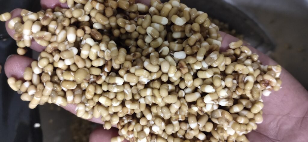
15 Hrs 
24 Hrs 
32Hrs 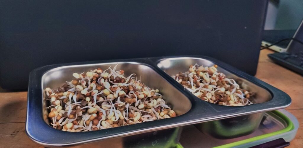
Final Result
- 12th – Jan – 2021
- —————————————————————————————————————————————————————————————–
- Problem Identification, experimentations, system designing, ideating possible solution, CAD modelling, setting of process flow, fabrication, testing & problem solving methodology – It been a great journey to experience of understanding & connecting these dots with out of box thinking.
- —————————————————————————————————————————————————————————————–
- Note :
- We identifed some issues with this system –
- Issue : As in trial we identify the issue with exact 180 degree rotation of vessel, in system we calculated the time delay for 180degree rotation but due to slight change in degree of 1st cycle lead to large change in further repetative cycles.
- Possible solution : To control the exact position of vessel we can add a limit switch to limit a motion at required angle by positioning the limit switch.
- Issue : The wiper motor shaft has slipped while trial because of the motor is used before and the threads on motor shaft are not proper so due to repetative cycles the attachment of motor shaft and mounting slipped at contact.
- Possible solution : Now we done a temporary solution by using araldite adhesive. But we have to use a motor with good threaded shaft.
- Issue: Water leakage thruogh vessel lid.
- Possible solution : We use a temporary cycle tube as a gasket which helped in overcoming the problem. But a proper gasket is recommended.
- Issue : As in trial we identify the issue with exact 180 degree rotation of vessel, in system we calculated the time delay for 180degree rotation but due to slight change in degree of 1st cycle lead to large change in further repetative cycles.
- We identifed some issues with this system –
- ——————————————————————————————————————————————————————————————


