introduction
In Week 2, we learned the basics of Embedded Programming and how embedded systems work in real-life applications. We installed the Thonny IDE, added the required boards, and uploaded programs to a microcontroller using MicroPython. We also explored Binary and Hexadecimal number systems, understood processor architecture, and compared different microcontrollers to learn their features and applications.
Embedded Programming
Embedded programming is the process of writing code for a microcontroller inside an electronic device. The program tells the device what to do and how to perform specific tasks. For example, it can turn an LED on or off, read data from a sensor, or control a motor. Embedded programming is widely used in everyday devices such as washing machines, smartwatches, home appliances, cars, and IoT devices.
Embedded Systems
An embedded system is a small computer built inside an electronic device to perform a specific task. It is designed to do one particular job efficiently and reliably. Embedded systems are used in many everyday devices such as washing machines, microwaves, cars, smartwatches, and home appliances. They use a microcontroller or processor to read inputs from sensors, process the data, and control outputs like LEDs, motors, or displays.

An embedded system receives input from sensors, buttons, or switches, processes the information, and then gives the required output by controlling devices such as LEDs, motors, displays, or buzzers. Because they are designed for a specific purpose, embedded systems are fast, reliable, and consume very little power.
Today, embedded systems are used in almost every field, including home appliances, automobiles, medical equipment, industrial machines, smart devices, and IoT applications. Common examples include washing machines, microwave ovens, smartwatches, traffic lights, printers, air conditioners, digital cameras, and cars.
Microcontroller
A microcontroller is a small computer on a single chip that controls electronic devices. It receives input from sensors or buttons, processes the data, and controls outputs like LEDs, motors, or displays. Microcontrollers are commonly used in embedded systems because they are small, low-cost, and efficient.
Examples: Arduino Uno (ATmega328P), ESP32, ESP32-C3, and RP2040.
Microprocessor
A microprocessor is the CPU of a computer on a single chip. It processes data and executes instructions. Unlike a microcontroller, it needs external memory and other components to work. Microprocessors are commonly used in computers, laptops, and smartphones.
Difference between microcontroller and microprocessor
| Microcontroller | Microprocessor |
|---|---|
| A small computer on a single chip. | A CPU on a single chip. |
| Has CPU, memory, and I/O ports built into one chip. | Has only the CPU and needs external memory and I/O devices. |
| Used for specific tasks. | Used for general-purpose computing. |
| Low power consumption. | Higher power consumption. |
| Best for embedded systems and electronic devices. | Best for computers, laptops, and smartphones. |
| Examples: ATmega328P, ESP32, ESP32-C3, RP2040 | Examples: Intel Core i5, AMD Ryzen, ARM Cortex-A |
Binary Number System
A binary number system is a number system that uses only two digits: 0 and 1. It is the fundamental language of computers because electronic circuits can easily represent two states: OFF (0) and ON (1).
Why is Binary Used?
- Computers understand only two electrical states:
- 0 = OFF (Low Voltage)
- 1 = ON (High Voltage)
- This makes binary reliable and easy for digital devices to process.
Examples
Applications of Binary
- Computers and laptops
- Microcontrollers (Arduino, ESP32, RP2040)
- Mobile phones
- Digital electronics
- Memory and data storage
- Communication systems
Binary is the language of computers. Every letter, number, image, sound, and video inside a computer is ultimately stored and processed as a combination of 0s and 1s.
Hexadecimal Number System
A hexadecimal number system is a base-16 number system that uses 16 symbols:
0, 1, 2, 3, 4, 5, 6, 7, 8, 9, A, B, C, D, E, F
Where:
- A = 10
- B = 11
- C = 12
- D = 13
- E = 14
- F = 15
Why is Hexadecimal Used?
- It represents large binary numbers in a short and easy-to-read format.
- 1 hexadecimal digit = 4 binary bits (1 nibble).
- It is widely used in programming, microcontrollers, memory addresses, and color codes.
Applications
- Memory addresses in computers
- Microcontrollers (Arduino, ESP32, RP2040)
- Programming and debugging
- HTML/CSS color codes (e.g., #FF0000 = Red)
- Embedded systems and digital electronics
Hexadecimal is a compact way to write binary numbers. Instead of writing long strings of 0s and 1s, we use the digits 0–9 and letters A–F, making the numbers easier to read and work with.
Arduino IDE installation
Arduino IDE
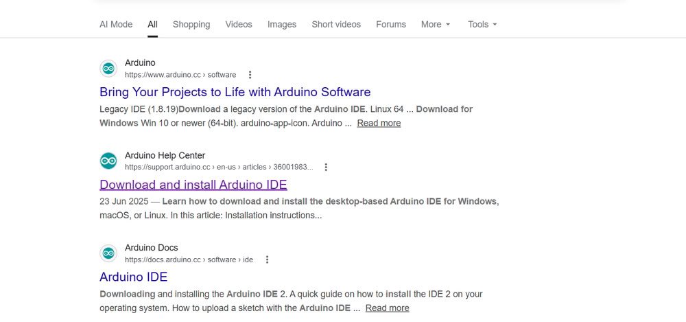
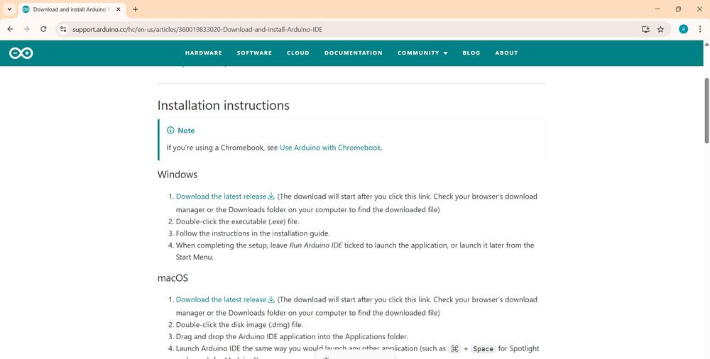
Arduino IDE (Integrated Development Environment) is a free software used to write, compile, and upload programs to Arduino boards and many other microcontroller boards such as ESP32, ESP32-C3, RP2040, and Raspberry Pi Pico. It provides a simple and user-friendly interface, making it easy for beginners and developers to create embedded system projects.
Features of Arduino IDE
- Simple and easy-to-use interface.
- Supports C/C++ programming language.
- Built-in code editor with syntax highlighting.
- One-click Verify (Compile) and Upload options.
- Serial Monitor for viewing and debugging output.
- Supports many development boards through Board Manager.
- Large collection of built-in and third-party libraries.
Development Workflow in Arduino IDE
- Install Arduino IDE.
- Select the board.
- Select the COM port.
- Write the code.
- Verify (Compile) the code.
- Upload the code.
- Test using the Serial Monitor.
- Modify and upload again if needed

thonny installation
Thonny IDE
Thonny IDE is a free and beginner-friendly software used to write, run, and debug Python and MicroPython programs. It is commonly used to program microcontroller boards such as ESP32, ESP32-C3, XIAO RP2040, and Raspberry Pi Pico.
Features of Thonny IDE
- Simple and easy-to-use interface.
- Supports Python and MicroPython.
- Built-in code editor with syntax highlighting.
- Easy to upload and run MicroPython programs.
- Built-in Shell to view program output.
- Debugging tools for finding and fixing errors.
- Supports multiple MicroPython-compatible boards.
Development Workflow in Thonny IDE
- Install Thonny IDE.
- Install MicroPython firmware (if required).
- Connect the microcontroller using a USB cable.
- Select the correct MicroPython Interpreter.
- Write the Python code.
- Run the code.
- Save the program to the board (
main.py). - Test and debug the program.
- Modify and run again if needed.


Microcontrollers and their Datasheets overview
1 . Arduino uno
Arduino Uno is one of the most popular and beginner-friendly microcontroller development boards. It is based on the ATmega328P microcontroller and is widely used for learning embedded systems, electronics, and IoT projects. It can read inputs from sensors and buttons and control outputs such as LEDs, motors, and displays.

datasheet for arduino uno
Features of Arduino Uno
- Based on ATmega328P microcontroller.
- 8-bit AVR architecture.
- 16 MHz clock speed.
- 14 Digital I/O pins (6 PWM pins).
- 6 Analog input pins.
- Operates at 5V.
- Supports UART, SPI, and I2C communication.
- Programmed using the Arduino IDE with C/C++.
- Powered through USB Type-B or an external power supply.
Applications
- LED control
- Sensor interfacing
- Home automation
- Robotics
- IoT learning
- Educational projects

Task:
Blink LED Using Arduino Uno
Objective
To learn the basic operation of the Arduino Uno by blinking an LED using the Arduino IDE.
Components Used
- Arduino Uno
- LED
- 220 Ω Resistor
- Breadboard
- Jumper Wires
- USB Cable
- Computer with Arduino IDE
Working
The program controls an external LED connected to the Arduino Uno. The LED turns ON for one second and then turns OFF for one second. This process repeats continuously, creating a blinking effect.
Arduino Code
voidsetup(){pinMode(13,OUTPUT);}voidloop(){digitalWrite(13,HIGH);delay(1000);digitalWrite(13,LOW);delay(1000);}Observation
The LED blinked successfully by turning ON for one second and OFF for one second repeatedly after the program was uploaded.
2 . xiao ESP32 C3
XIAO ESP32-C3 is a compact and powerful microcontroller development board developed by Seeed Studio. It is based on the ESP32-C3 microcontroller and supports Wi-Fi and Bluetooth Low Energy (BLE), making it ideal for IoT and wireless projects. Despite its small size, it offers excellent performance and low power consumption.

Features of XIAO ESP32-C3
- Based on ESP32-C3 microcontroller.
- 32-bit RISC-V architecture.
- Single-core processor.
- Up to 160 MHz clock speed.
- 3.3V operating voltage.
- Built-in Wi-Fi (2.4 GHz) and Bluetooth Low Energy (BLE 5.0).
- 11 GPIO pins with PWM, I2C, SPI, and UART support.
- 4 MB Flash memory and 400 KB SRAM.
- USB Type-C interface.
- Supports Arduino IDE and Thonny IDE (MicroPython).
Applications
- IoT projects
- Smart home devices
- Wireless sensor networks
- Wearable electronics
- Home automation
- Robotics
Blink LED Using Seeed XIAO ESP32-C3

Task:
Blink LED Using Seeed XIAO ESP32-C3
To learn the basic operation of the Seeed XIAO ESP32-C3 by blinking its onboard LED using the Arduino IDE.
Components Used
- Seeed XIAO ESP32-C3
- USB Type-C Cable
- Computer with Arduino IDE
Working
The program controls the onboard LED of the XIAO ESP32-C3. The LED turns ON for one second and then OFF for one second. This process repeats continuously, demonstrating basic digital output control.
Arduino Code
voidsetup(){pinMode(LED_BUILTIN,OUTPUT);}voidloop(){digitalWrite(LED_BUILTIN,HIGH);delay(1000);digitalWrite(LED_BUILTIN,LOW);delay(1000);}Observation
The onboard LED blinked successfully by turning ON for 1 second and OFF for 1 second repeatedly after the program was uploaded.
3 . xiao RP2040
XIAO RP2040 is a compact and powerful microcontroller development board developed by Seeed Studio. It is based on the RP2040 microcontroller designed by Raspberry Pi. The board is small, fast, and suitable for embedded systems, robotics, and electronics projects.

Features of XIAO RP2040
- Based on RP2040 microcontroller.
- 32-bit ARM Cortex-M0+ architecture.
- Dual-core processor.
- Up to 133 MHz clock speed.
- 3.3V operating voltage.
- 11 GPIO pins with PWM, I2C, SPI, and UART support.
- 2 MB Flash memory and 264 KB SRAM.
- USB Type-C interface.
- Supports Arduino IDE and Thonny IDE (MicroPython).
Applications
- Embedded systems
- Robotics
- Sensor interfacing
- Automation projects
- Wearable devices
- Educational projects
Task:
Blink NeoPixel LED Using Seeed XIAO RP2040
To learn how to control the onboard NeoPixel RGB LED of the Seeed XIAO RP2040 using the Arduino IDE.
Components Used
- Seeed XIAO RP2040
- USB Type-C Cable
- Computer with Arduino IDE
Working
The program controls the onboard NeoPixel RGB LED of the XIAO RP2040. The LED is programmed to turn ON with a selected color and then turn OFF after a one-second delay. This process repeats continuously, creating a blinking effect.
Arduino Code
#include<Adafruit_NeoPixel.h>#definePIN_NEOPIXEL 12#defineNUMPIXELS 1Adafruit_NeoPixelpixels(NUMPIXELS,PIN_NEOPIXEL,NEO_GRB+NEO_KHZ800);voidsetup(){pixels.begin();}voidloop(){pixels.setPixelColor(0,pixels.Color(255,0,0)); // Redpixels.show();delay(1000);pixels.clear();pixels.show();delay(1000);}Observation
The onboard NeoPixel RGB LED blinked successfully by turning red for one second and then turning OFF for one second repeatedly after the program was uploaded.
4 . ESP32 WROOM
ESP32-WROOM is a powerful microcontroller development module developed by Espressif Systems. It is based on the ESP32 microcontroller and comes with built-in Wi-Fi and Bluetooth, making it ideal for IoT, wireless communication, and smart device applications.

Features of ESP32-WROOM
- Based on ESP32 microcontroller.
- 32-bit Xtensa LX6 architecture.
- Dual-core processor.
- Up to 240 MHz clock speed.
- 3.3V operating voltage.
- Built-in Wi-Fi (2.4 GHz) and Bluetooth (Classic + BLE).
- Up to 34 GPIO pins with PWM, ADC, DAC, I2C, SPI, UART, and I2S support.
- 4 MB Flash memory and 520 KB SRAM.
- Supports Arduino IDE, ESP-IDF, and Thonny IDE (MicroPython).
- Available on many development boards with Micro-USB or USB Type-C.
Applications
- IoT projects
- Smart home automation
- Wireless sensor networks
- Robotics
- Industrial automation
- Web servers and IoT gateways

Task:
Blink LED Using ESP32-WROOM
To learn the basic operation of the ESP32-WROOM by blinking an LED using the Arduino IDE.
Components Used
- ESP32-WROOM Development Board
- LED
- 220 Ω Resistor
- Breadboard
- Jumper Wires
- USB Cable
- Computer with Arduino IDE
Working
The program controls an external LED connected to the ESP32-WROOM. The LED turns ON for one second and then turns OFF for one second. This process repeats continuously, creating a blinking effect.
Arduino Code
constintledPin = 2;voidsetup(){pinMode(ledPin,OUTPUT);}voidloop(){digitalWrite(ledPin,HIGH);delay(1000);digitalWrite(ledPin,LOW);delay(1000);}Observation
The LED blinked successfully by turning ON for one second and OFF for one second repeatedly after the program was uploaded.
5 . Raspberry pi pico
Raspberry Pi Pico is a low-cost and powerful microcontroller development board developed by the Raspberry Pi Foundation. It is based on the RP2040 microcontroller and is designed for embedded systems, electronics, robotics, and IoT projects. It is easy to program and is suitable for both beginners and advanced users.

Features of Raspberry Pi Pico
- Based on RP2040 microcontroller.
- 32-bit ARM Cortex-M0+ architecture.
- Dual-core processor.
- Up to 133 MHz clock speed.
- 3.3V operating voltage.
- 26 GPIO pins.
- 3 Analog (ADC) input pins.
- 16 PWM channels.
- 264 KB SRAM.
- 2 MB Flash memory.
- Supports UART, SPI, and I2C communication.
- Micro-USB interface.
- Supports Arduino IDE, Thonny IDE (MicroPython), and C/C++ SDK.
Applications
- Embedded systems
- Robotics
- Sensor interfacing
- Home automation
- IoT projects
- Educational projects
Task:
Blink LED Using Raspberry Pi Pico
To learn the basic operation of the Raspberry Pi Pico by blinking its onboard LED using the Arduino IDE.
Components Used
- Raspberry Pi Pico
- USB Cable
- Computer with Arduino IDE
Working
The program controls the onboard LED of the Raspberry Pi Pico. The LED turns ON for one second and then turns OFF for one second. This process repeats continuously, creating a blinking effect.
Arduino Code
voidsetup(){pinMode(LED_BUILTIN,OUTPUT);}voidloop(){digitalWrite(LED_BUILTIN,HIGH);delay(1000);digitalWrite(LED_BUILTIN,LOW);delay(1000);}Observation
The onboard LED blinked successfully by turning ON for one second and OFF for one second repeatedly after the program was uploaded.
Group assignment
During the group assignment, we compared different development boards, including the Arduino Uno, XIAO ESP32-C3, XIAO RP2040, ESP32-WROOM, and Raspberry Pi Pico. We studied their processor architecture, CPU speed, memory, GPIO pins, communication interfaces, PWM, ADC, wireless connectivity, and power consumption. This comparison helped us understand the features, capabilities, and suitable applications of each board, making it easier to choose the right microcontroller for different embedded system and IoT projects.”

Comparison of Microcontroller Architectures
Comparison of Microcontroller Architectures is the process of comparing different microcontroller architectures based on their design, performance, processing capability, power consumption, and features. It helps in understanding the differences between architectures such as AVR, ARM Cortex-M0+, Xtensa, and RISC-V, and selecting the most suitable microcontroller for a specific embedded application.


| Parameter | Arduino Uno | ESP32-WROOM | ESP32-C3 | XIAO RP2040 | Raspberry Pi Pico |
|---|---|---|---|---|---|
| Microcontroller | ATmega328P | ESP32-WROOM | ESP32-C3 | RP2040 | RP2040 |
| Core | Single Core | Dual Core | Single Core | Dual Core | Dual Core |
| Architecture | 8-bit AVR RISC | 32-bit Xtensa LX6 | 32-bit RISC-V | 32-bit ARM Cortex-M0+ | 32-bit ARM Cortex-M0+ |
| Clock Speed | 16 MHz | Up to 240 MHz | Up to 160 MHz | Up to 133 MHz | Up to 133 MHz |
| Operating Voltage | 5 V | 3.3 V | 3.3 V | 3.3 V | 3.3 V |
| GPIO Voltage | 5 V | 3.3 V | 3.3 V | 3.3 V | 3.3 V |
| Digital Pins | 14 | Up to 34 | Up to 22 | Up to 11 | 26 |
| PWM Pins | 6 | Up to 16 | Up to 6 | Up to 11 | 16 |
| Analog Pins | 6 | Up to 18 | Up to 6 | Up to 4 | 3 (ADC channels) |
| Communication | UART, SPI, I2C | UART, SPI, I2C, I2S | UART, SPI, I2C | UART, SPI, I2C | UART, SPI, I2C |
| Wi-Fi | No | Yes | Yes | No | No |
| Bluetooth | No | Yes | Yes (BLE) | No | No |
| Programming Language | C/C++ | C/C++, MicroPython | C/C++, MicroPython | C/C++, MicroPython | C/C++, MicroPython |
| On-board LED Pin | D13 | GPIO2 | GPIO8 | GPIO25 | GPIO25 |
| Flash Memory | 32 KB | 4 MB | 4 MB | 2 MB | 2 MB |
| RAM | 2 KB SRAM | 520 KB SRAM | 400 KB SRAM | 264 KB SRAM | 264 KB SRAM |
| USB Interface | USB Type-B | Micro-USB | USB Type-C | USB Type-C | Micro-USB |
| Advantages | Best for beginners | High performance with Wi-Fi & Bluetooth | Low power, RISC-V with Wi-Fi & BLE | Compact, fast dual-core board | Low-cost, fast dual-core development board |
Development Workflow Comparison
Development Workflow Comparison is the process of comparing the software tools and programming steps used for different embedded systems. It includes comparing the IDE, programming language, compiler, uploader tool, firmware, and the workflow of writing, compiling, uploading, testing, and debugging code on different microcontrollers such as Arduino Uno, ESP32, and RP2040 boards.
| Toolchain Component | Arduino Uno | ESP32-WROOM | ESP32-C3 | XIAO RP2040 | Raspberry Pi Pico |
|---|---|---|---|---|---|
| Architecture | AVR 8-bit | Xtensa 32-bit | RISC-V 32-bit | ARM Cortex-M0+ 32-bit | ARM Cortex-M0+ 32-bit |
| Programming Language | C/C++ | C/C++, MicroPython | C/C++, MicroPython | C/C++, MicroPython | C/C++, MicroPython |
| IDE (Editor) | Arduino IDE | Arduino IDE, Thonny IDE | Arduino IDE, Thonny IDE | Arduino IDE, Thonny IDE | Arduino IDE, Thonny IDE |
| Compiler | AVR-GCC | Xtensa-ESP32-GCC | RISC-V GCC | ARM GCC (arm-none-eabi-gcc) | ARM GCC (arm-none-eabi-gcc) |
| Uploader Tool | avrdude | esptool | esptool | UF2 Bootloader / bossac | UF2 Bootloader |
| Firmware | Arduino Bootloader | ESP32 Firmware / MicroPython Firmware | ESP32-C3 Firmware / MicroPython Firmware | RP2040 Firmware / MicroPython Firmware | RP2040 Firmware / MicroPython Firmware |
| Connection Type | USB Type-B | Micro-USB | USB Type-C | USB Type-C | Micro-USB |
| Execution Method | Compiled and Uploaded | Compiled or Interpreted | Compiled or Interpreted | Compiled or Interpreted | Compiled or Interpreted |
Experience
During this group assignment, we compared different microcontroller boards, including Arduino Uno, ESP32-WROOM, XIAO ESP32-C3, XIAO RP2040, and Raspberry Pi Pico. We studied their processor architecture, clock speed, memory, communication interfaces, and programming support. This comparison helped us understand the strengths and limitations of each board and how to choose the right microcontroller for different embedded system projects. It also improved our understanding of embedded hardware and development tools.
Development Workflow (Arduino IDE)
- Install Arduino IDE – Download and install the Arduino IDE.
- Select the Board – Choose the correct microcontroller board (e.g., Arduino Uno, ESP32, XIAO RP2040).
- Select the Port – Choose the COM port connected to the board.
- Write the Code – Create or open the Arduino sketch (.ino).
- Verify (Compile) – Check the code for errors by compiling it.
- Upload the Code – Upload the compiled program to the microcontroller.
- Run the Program – The microcontroller executes the uploaded program.
- Monitor Output – Use the Serial Monitor to view data or debug the program.
- Modify and Repeat – Edit the code, compile, upload, and test again until the desired result is achieved.
Development Workflow (MicroPython)
- Install Thonny IDE – Download and install the Thonny IDE.
- Install MicroPython Firmware – Flash the MicroPython firmware onto the microcontroller (if required).
- Connect the Board – Connect the microcontroller to the computer using a USB cable.
- Select the Interpreter – Choose the correct MicroPython interpreter and COM port in Thonny.
- Write the Code – Create a Python (
.py) program. - Run the Code – Execute the program directly from Thonny.
- Save the Program – Save the code to the board (e.g.,
main.py) for automatic execution on startup. - Test and Debug – Check the output, fix errors, and run the program again.
- Modify and Repeat – Update the code, save, and test until the desired result is achieved.
Comparison Summary
- Arduino IDE uses C/C++, while MicroPython uses Python.
- Arduino IDE compiles the code before uploading, whereas MicroPython executes the code through the interpreter.
- Arduino IDE is suitable for high-performance and production projects.
- MicroPython is easier to learn and is ideal for rapid prototyping and beginners.
- Both workflows support coding, testing, debugging, and uploading programs to microcontrollers.
- The choice between them depends on the project requirements, performance needs, and ease of development.
individual assignment
Task:
During this assignment, we soldered the header pins on the Seeed XIAO RP2040 development board and learned the correct soldering technique to ensure proper electrical connections.
After completing the soldering, my individual assignment was to write and upload a Blink LED program using the Arduino IDE. The code successfully blinked the onboard LED, confirming that the board was working correctly. Through this activity, I gained practical experience in soldering, programming a microcontroller, uploading code, and testing embedded hardware.


soldering to the xiao RP2040

During the group assignment, we programmed the Seeed XIAO RP2040 to control its onboard RGB LED using the Arduino IDE. The program was designed so that the user could enter a color name such as Red, Green, or Blue in the Serial Monitor, and the onboard RGB LED would immediately change to the selected color. This assignment helped us understand serial communication, user input handling, RGB LED control, and microcontroller programming while demonstrating how hardware can interact with commands received from a computer
#include <Adafruit_NeoPixel.h>
#define LED_POWER 11 // Enable power to the RGB LED
#define LED_PIN 12 // Data pin for the WS2812 RGB LED
#define NUMPIXELS 1
Adafruit_NeoPixel rgb(NUMPIXELS, LED_PIN, NEO_GRB + NEO_KHZ800);
void setup() {
pinMode(LED_POWER, OUTPUT);
digitalWrite(LED_POWER, HIGH); // Turn ON power to RGB LED
rgb.begin();
rgb.clear();
rgb.show();
Serial.begin(115200);
while (!Serial);
Serial.println(“===== XIAO RP2040 RGB Control =====”);
Serial.println(“Commands:”);
Serial.println(“red”);
Serial.println(“green”);
Serial.println(“blue”);
Serial.println(“yellow”);
Serial.println(“cyan”);
Serial.println(“purple”);
Serial.println(“white”);
Serial.println(“off”);
}
void loop() {
if (Serial.available()) {
String cmd = Serial.readStringUntil('\n');cmd.trim();if (cmd == "red") rgb.setPixelColor(0, rgb.Color(255, 0, 0));else if (cmd == "green") rgb.setPixelColor(0, rgb.Color(0, 255, 0));else if (cmd == "blue") rgb.setPixelColor(0, rgb.Color(0, 0, 255));else if (cmd == "yellow") rgb.setPixelColor(0, rgb.Color(255, 255, 0));else if (cmd == "cyan") rgb.setPixelColor(0, rgb.Color(0, 255, 255));else if (cmd == "purple") rgb.setPixelColor(0, rgb.Color(255, 0, 255));else if (cmd == "white") rgb.setPixelColor(0, rgb.Color(255, 255, 255));else if (cmd == "off") rgb.setPixelColor(0, rgb.Color(0, 0, 0));rgb.show();}
}
code for RGB LED Control Using Serial Monitor
Conclusion
Through these assignments, I gained a strong understanding of embedded systems and microcontroller programming. I learned how to compare different development boards, solder header pins on the Seeed XIAO RP2040, and program the onboard LEDs using the Arduino IDE. I also understood serial communication by controlling the onboard RGB LED through the Serial Monitor. These hands-on activities improved my practical skills in hardware assembly, programming, circuit testing, and debugging. Overall, this week provided me with a solid foundation in embedded programming and increased my confidence in working with microcontrollers for future electronics and IoT projects.
end of week 2
.