Introduction
Distilled water is a fundamental resource required for experimental, analytical, and solution-preparation work in chemistry laboratories. Reliable production and availability of high-purity distilled water ensures accuracy and reproducibility in laboratory processes. This project focuses on diagnosing performance inefficiencies in the existing distillation unit and outlining a practical path for system optimization.
Current System Description
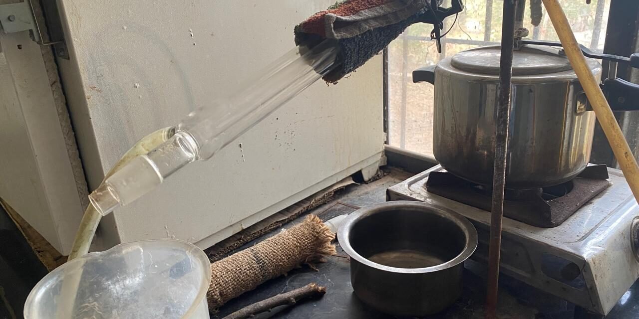
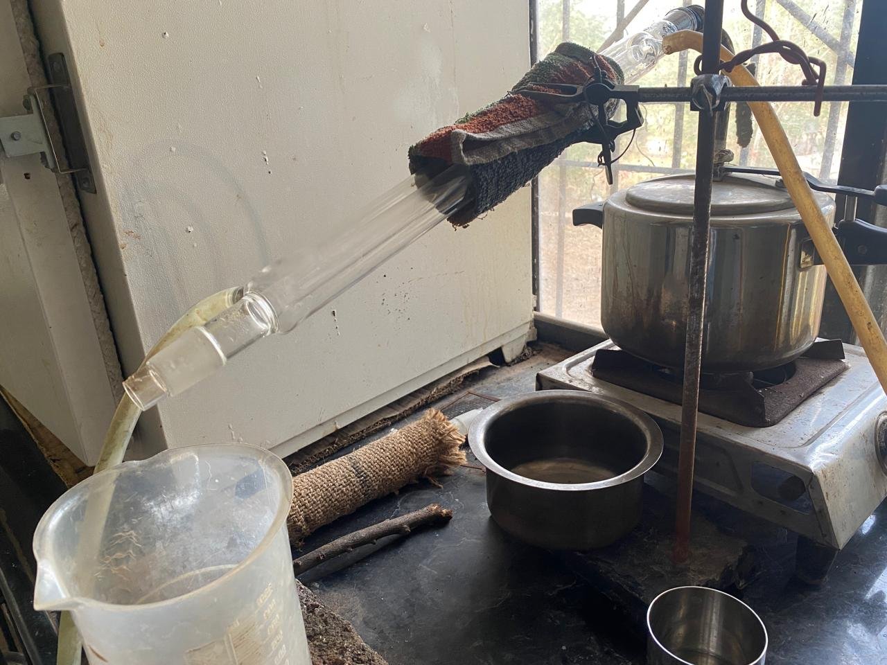
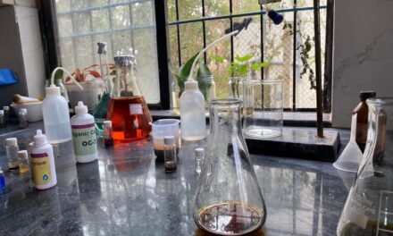
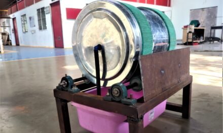
The distillation setup consists of a pressure cooker acting as the steam boiler, an inclined Liebig condenser for condensation, water circulation hoses connected to a cooling bucket, and a pump that assisted water flow. The condenser and outlet pipe are supported using a lab stand and clamps.
Observed Problem
The unit is producing only 1–2 liters of distilled water in 7 hours, instead of the expected 5 liters in 7 hours.
The major reasons identified are:
- Insufficient cooling of the condenser, leading to steam escaping without condensing into liquid.
- Warm water flow at the condenser inlet, reducing heat exchange efficiency.
- Steam leakage from the cork joint around the metal steam outlet pipe, causing vapor and pressure loss.
Working Principle of the Distillation Unit
- Thermal Energy Application – Water is heated inside the boiler until it reaches boiling temperature and converts into steam.
- Vapor Transportation – The generated steam moves through a vapor outlet pathway toward the condenser.
- Cooling Mechanism – Cold water circulated around the condenser removes heat from the steam.
- Phase Transition – Loss of thermal energy causes the vapor to condense into liquid distilled water.
- Distillate Collection – The condensed liquid exits the condenser and is collected in a receiving vessel.
The efficiency of this cycle is directly influenced by cooling water temperature, circulation speed, condenser surface area, vapor sealing integrity, and heat retention in the boiler.
Point for Heating Power Calculation (kW Required)
As part of the system design process, a key requirement assigned was to calculate the heating power (in kW) necessary for the gas burner to support efficient steam generation in the distillation system. The calculation was performed based on experimental observations from the reference distillation unit.
Heating Power Requirement for 5 L Distilled Water in 7 Hours
- Latent heat of vaporization per liter of water
Q1 = 2260 kJ/L
- Total heat required for 5 L
Q5 = 2260×5 = 11300 kJ
- Convert kJ to kWh
E = 11300 ÷ 3600 = 3.139 kWh ≈ 3.13 kWh
- Theoretical power required for 7 hours (100% efficiency)
Ptheoretical = 3.13 ÷ 7 = 0.447 kW ≈ 0.45 kW
- Apply 50% system efficiency (50% heat loss)
Ppractical = 0.45 ÷ 0.50 =0.9 kW
- Convert kW → Watts
Pfinal = 0.9 × 1000 = 900 W
Energy Consumption Analysis for Gas Burner Operation
To understand the relationship between flame intensity and energy consumption, heat energy released by a gas burner was evaluated for 1 hour under three operating conditions:
High Flame (for one hour) :
Power = 3 kWh [~2.5 to 3.5 kWh ]
Energy = 3 kWh
3 kWh × 3600 kJ = 10800 kJ
Energy consumed at high flame for 1 hour = 10800 kJ
Medium Flame (for one hour) :
Power = 1.5 kWh [ ~1.5 to 2.0 kWh ]
Energy = 1.5 kWh
1.5 kWh × 3600 kJ = 5400 kJ
Energy consumed at medium flame for 1 hour = 5400 kJ
Low Flame (for one hour) :
Low Flame:
Power = 0.7 kWh [~0.5 to 1.0 kWh ]
Energy = 0.7 kWh
0.7 kWh × 3600 kJ = 2520 kJ
Energy consumed at low flame for 1 hour = 2520 kJ
These values reflect the thermal energy supplied to the system, not the amount recovered as distilled water.
Burner power estimation methodology:
The heat output of an LPG burner is typically stated in British Thermal Units per hour (BTU/hr). According to standard conversion factors (1 kW ≈ 3412 BTU/hr), a burner with an output of 8500–12000 BTU/hr corresponds to approximately 2.5–3.5 kW. A representative value of 3 kW was used for high flame calculations. For the medium flame 1.5-2.0 and For the low flame, using a lower BTU/hr range (2000–4000 BTU/hr) yields approximately 0.5–1.0 kW and 0.7 kW was used for practical calculation.
- High flame ≈ 3.0 kW
- Medium flame ≈ 1.5 kW
- Low flame ≈ 0.7 kW
Burner Energy and Distillation Output:
The energy supplied by the gas burner does not fully convert into distilled water because thermal systems experience energy losses due to steam leakage, heating of metal surfaces, warming of condenser water, and dissipation into the environment. Only the portion of heat that successfully completes the vaporization to condensation cycle contributes to distillate formation.
Calculations (with losses)
Assuming 50% system heat utilization :
High flame:
10800 × 0.50 = 5400 kJ
5400 ÷ 2260 ≈ 2.39 L/hr
Medium flame:
5400 × 0.50 = 2700 kJ
2700 ÷ 2260 ≈ 1.20 L/hr
Low flame:
2520 × 0.50 = 1260 kJ
1260 ÷ 2260 ≈ 0.56 L/hr
Experimental Temperature Study of Cooker Body and Lid
Following the energy calculations with losses, an experimental study was conducted to analyze heat loss from the distillation unit. The surface temperatures of the cooker body and cooker lid were measured using an IR thermometer at 10-minute intervals during operation.(With and Without Insulation)
The experiment began at 12:00 PM and continued until 6:20 PM, giving a total operating time of 380 minutes. Temperature readings were recorded until approximately 300 mL of water remained inside the cooker.
Complete vaporization of the water was not attempted because operating the cooker until fully dry can cause:
- Overheating of the cooker base
- Damage to the cooker and sealing components
- Risk of safety valve activation
- Distortion of cooker shape due to thermal stress
Therefore, the experiment was intentionally stopped with a small residual volume of water to ensure safe and controlled operation.
This data represents the non-insulated and insulated condition of the system and was used to identify thermal losses and justify the need for insulation.
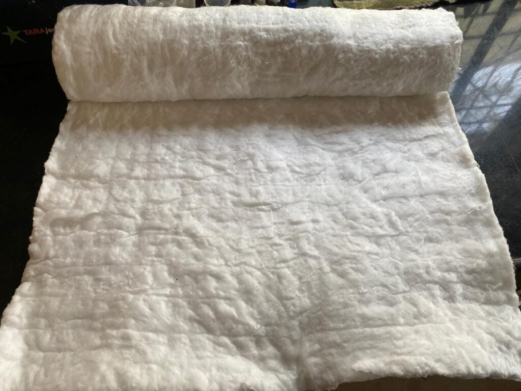
Selection of Insulation Material
The temperature study clearly demonstrated that surface heat loss is a major limiting factor in the performance of the distillation unit. Even when sufficient thermal energy is supplied by the burner, a significant fraction escapes into the environment instead of contributing to water vaporization. After reviewing commonly available insulation materials such as glass wool, mineral wool, and ceramic wool, ceramic wool was selected as the most suitable insulation material for this setup.
The selection was based on the following reasons:
- Widely used in furnaces, boilers, and high-temperature lab equipment
- High temperature resistance (typically up to 1000–1200 °C)
- Very low thermal conductivity, reducing heat loss effectively
- Lightweight and flexible, allowing easy wrapping around curved surfaces
- Chemically inert and stable at prolonged operating temperatures
Purpose of Insulation in the Distillation Unit:
The primary purposes of insulation in this setup are:
- To reduce convective and radiative heat losses from the cooker body and lid
- To maintain higher internal water temperature with lower fuel input
- To achieve faster vapor generation at the same flame level
- To improve overall thermal efficiency of the system
- To reduce total distillation time and gas consumption
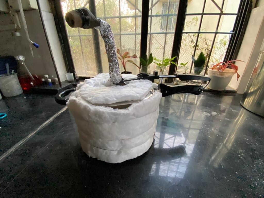
Insulation Application to Heat Retention Surfaces
Insulation Material Used : Ceramic Wool
Thickness Used: 15 mm
Calculations
1. Cooker Body (Cylindrical Surface)
Given:
Diameter, D = 18 cm
Height, h = 15 cm
Circumference:
C = π × D
C = 3.14 × 18
C = 56.52 cm ≈ 60 cm (considering overlap)
Surface Area of Cooker Body:
A = C × h
A = 60 × 15
A = 900 cm²
2. Cooker Lid (Circular Surface)
Given:
Diameter = 18 cm
Radius, r = 9 cm
Area of Lid:
A = π × r²
A = 3.14 × 9²
A = 254.34 cm² ≈ 260 cm²
3. Metal Steam Pipe
Given:
Length, L = 14 cm
Diameter, D = 2 cm
Circumference:
C = π × D
C = 3.14 × 2
C = 6.28 cm ≈ 7 cm
Surface Area of Pipe:
A = C × L
A = 7 × 14
A = 98 cm² ≈ 100 cm²
4. Total Insulation Area Required
Total Area:
A = 900 + 260 + 100
A = 1260 cm²
Unit conversion:
1260 cm² = 0.13 m²
Comparative Performance Analysis (Before and After Insulation):
To evaluate the effect of thermal insulation on the performance of the distillation unit, a comparative analysis was carried out between uninsulated and insulated operating conditions. The insulation was applied to the cooker body, cooker lid, and metal steam outlet pipe using ceramic wool.
| Parameter | Without Insulation | With Insulation |
| Initial water volume (L) | 4 | 4 |
| Distilled Water Collected(L) | 3.2 | 3.7 |
| Total Operating time (min) | 380 | 350 |
| Distillation rate (L/hr) | 600 | 650 |
| Atmospheric losses (ml) | 500 | 100 |
| Residual water in cooker (ml) | 300 | 200 |
| Cooker outer surface temperature (°C) | HIgher | ~50-53 |
The detailed experimental data for both operating conditions without insulation and with insulation are compiled in a single spreadsheet. The dataset includes time-resolved surface temperature measurements of the cooker body and lid, flame intensity variations, and corresponding operating durations. The spreadsheet is provided below to support the comparative analysis discussed above.
The compiled dataset enables direct comparison of thermal behavior and distillation performance before and after insulation under similar operating conditions.
Induction Heating Trial and Energy Analysis:
To further explore methods of improving the performance of the distillation unit, an induction heating trial was conducted on the insulated setup. Unlike the gas burner, an induction cooktop provides controlled electrical heating with minimal convective losses and stable power input, making it a promising alternative for steam generation in distillation.
Experimental Procedure:
The induction cooktop was operated in two stages:
- First 30 minutes at 1800 W to rapidly heat the vessel and bring the water to boiling.
- After boiling was established, the power was reduced to 1000 W for continued distillation.
This strategy ensured quick attainment of boiling temperature followed by a controlled vapor-generation phase, reducing unnecessary energy waste.
Energy Supplied by Induction:
The total electrical energy supplied during the experiment was calculated based on the induction power settings and operating time.
Phase 1 – Initial Heating (1800 W for 30 min)
Phase 2 – Distillation Phase (1000 W for 54 min)
54 minutes = 0.9 hours
Total electrical energy supplied:
This value represents the total energy input from induction heating over the 84 minute period of operation.
Theoretical Practical Distillation output:
Practical Distillation Output
Using the latent heat of vaporization of water (approximately 2257 kJ/kg), the theoretical maximum water that could be vaporized from the supplied energy is estimated as:m=22576480≈2.87 kg≈2.87 L
This is an ideal estimate assuming 100% energy utilization with no losses. In reality, heat losses through the vessel walls, insulation gaps, and condenser inefficiencies reduce the usable energy.
Assuming a practical energy utilization range of 60–70%, the estimated distilled output becomes:
- At 60%:
- At 70%:
These values are consistent with the observed distillation performance, where distilled water was generated at a noticeably higher rate compared to the gas heated runs.
Interpretation and Significance:
The induction trial highlights several important points:
- Controlled power input: Switching from 1800 W to 1000 W after boiling minimized energy waste while sustaining vapor generation.
- Efficient heat delivery: Electrical induction coupling delivers heat directly to the metal vessel base with fewer losses than an open flame, leading to faster vapor production.
- Higher distillation rates: Even with energy considerations, induction produced distilled water at a higher rate compared to the uninsulated and insulated gas burner runs over equivalent time periods.
- Energy utilization trend: While absolute energy per litre distilled remains an approximation without direct calorimetric measurement, the relative comparison shows clear potential for induction heating in distillation.
Conclusion
This project focused on improving the performance of a laboratory distillation unit by identifying heat losses reducing time required and reducing energy wastage that is fuel consumption. Experimental observations showed that significant thermal energy was lost from the cooker body, lid, and steam outlet pipe in the uninsulated setup, resulting in low distillation efficiency and longer operating time.
Application of ceramic wool insulation reduced surface heat loss, improved the distillation rate, and decreased the total time required for distilled water collection. This confirms that thermal insulation plays a key role in enhancing the efficiency of small-scale distillation systems.
Induction heating trials showed quicker boiling and better control, giving higher distillation in less time due to direct heating and fewer losses. Earlier IR thermometer readings had instrumental error, so thermocouple measurements were later used for accuracy.
Distillation performance mainly depends on heat retention, sealing, and controlled heating. Insulation and induction heating clearly improve efficiency, reduce time, and save energy, making the system more practical for laboratory distilled water production.
The project aimed to achieve 5 L of distilled water in 7 hours by improving heat utilization. Insulation and controlled heating reduced heat losses and increased the distillation rate, while induction trials showed faster and more efficient vapor generation.
