In our food lab, we currently lack equipment capable of effectively extracting moisture from various substances.
Therefore, they resorted to using a heat oven; however, a notable drawback they encountered is the challenge of obtaining readings due to the need to repeatedly turn the heat oven on and off for each measurement.
So they used a heat oven for it. But the drawback/ facing problems of using a heat oven is there is difficulty to take readings through it and also at every reading they have to turn that heat oven on and off.
In order to address this issue, I am creating an Infrared moisture-balancing device to minimize the problem.
(Sanket Valse blog conclusion : In conclusion, a low-cost DIY IR moisture balance can be a practical and budget-friendly solution for accurately measuring moisture content in various samples. It provides significant cost savings compared to expensive commercial alternatives and has lower long-term operating expenses. It offers significant savings compared to expensive commercial options and has lower long-term operational costs.
Blog Link : https://vadic.vigyanashram.blog/2021/04/29/infrared-moisture-balance/ )
Objective :
The aim is to develop a standardized protocol for constructing an infrared balance device, with a specific emphasis on:
- The device should be capable of effectively extracting moisture from various substances without compromising accuracy or requiring excessive time.
- It should provide easy access to readings without the need for repeated turning on and off.
- The device should automate the process as much as possible to minimize manual intervention and streamline operations.
- The device should provide accurate readings to ensure reliable results from various substances.
Components Required :
To construct an infrared balance device, several essential components are required:
- 1 kg load cell: A strain gauge load cell serves as the primary sensor for measuring weight accurately. A load cell is a highly effective electro-mechanical sensor that is commonly used to measure force or weight. It functions by utilizing the established transference between an applied force, material deformation, and the flow of electricity.
- HX711: The HX711 is a highly precise 24-bit analog-to-digital converter (ADC) that has been specifically designed to cater to weighing scale applications. Its primary function is to interface directly with a bridge sensor, thereby providing an accurate and reliable measurement of weight.
- ESP32 microcontroller: The ESP32 is a microcontroller chip that enables Wi-Fi and Bluetooth connectivity for embedded devices, particularly for Internet of Things (IoT) applications. Although the ESP32 technically refers to the chip, the development boards and modules that integrate this chip are also commonly referred to as ESP32 by the manufacturer. The ESP32 is extensively used in various domains, including mobile devices, wearable technology, and IoT applications.
- 16×2 liquid crystal display (LCD): 16×2 LCDs are a popular choice for compact displays, capable of displaying 16 characters on two lines. Each character is composed of a 5×7 pixel matrix. These displays find widespread use in the fields of electronics, robotics, and embedded systems, and are primarily utilized for displaying text-based information. Typically operated at 5.3V, they are designed to interface with microcontrollers.
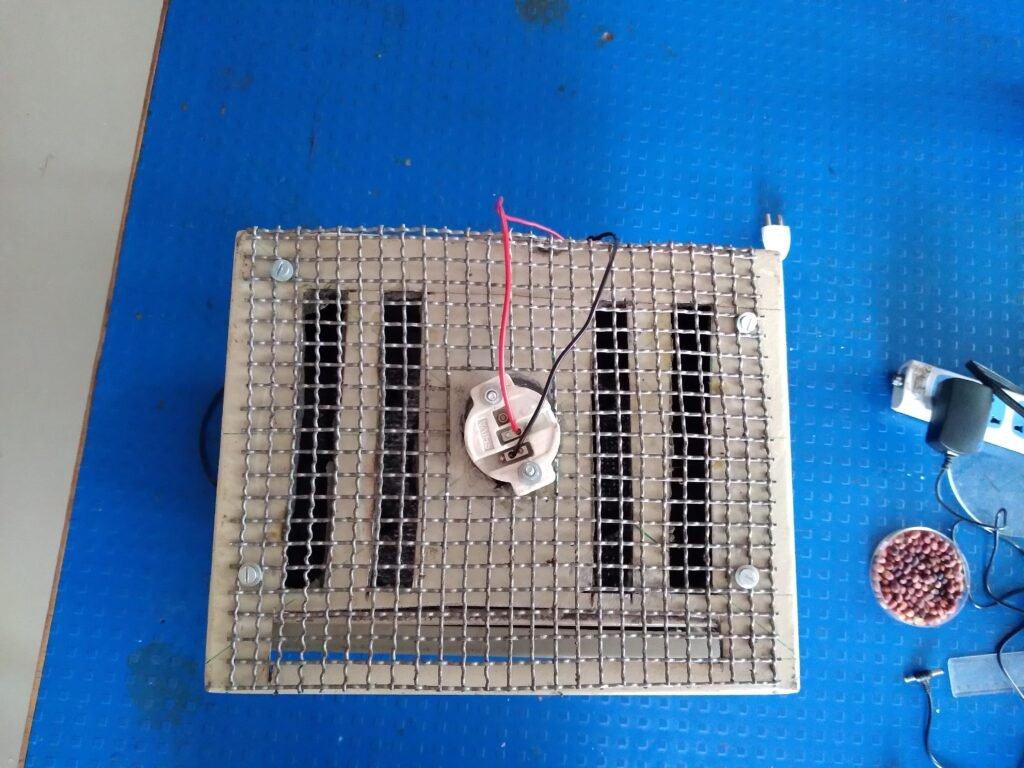
- Infrared (IR) lamp: Utilized for moisture removal, activated based on weight readings.
- Relay: A power relay module is an electrical switch that is activated by an electromagnet. This electromagnet is stimulated by a separate low-power signal from a microcontroller, which when activated pulls to either open or close an electrical circuit.
- Temperature Sensor (DS18B20): The DS18B20 sensor measures temperature and sends the temperature data digitally to a connected device using a single wire for communication.
Procedure :
When Mr. Dixit Sir told me about this project for the first time, he explained to me exactly how the Infrared Balance device is used and how it works. (An infrared balance device measures changes in a sample’s mass as it absorbs or emits heat from an infrared radiation source.) And with that, it said that whatever moisture substance we are going to put on it will be a minimum of 10 grams and a maximum of 100 grams and from this, I guessed that the load cell I am going to use should be 1 kg.
(Why do we use 1kg load cell…?
1. Requirement of project.
2. Capacity: The load cell should be capable of accurately measuring loads up to 1kg
3. Accuracy: The load cell should have a high level of accuracy suitable for the intended application. For a 1kg load cell, this results in mass change detection down to 0.0001g.
4. Sensitivity: Sensitivity refers to the smallest change in load that the load cell can detect reliably.)
After this I started my project I decided to first calibrate the load cell, so I connected the load cell with model HX711 and connected this connection with ESP32.
After that, under the guidance of Suhas sir, I took the load cell calibration code in Arduino IDE software and downloaded the required libraries, then I uploaded the code to ESP 32 and when the code was properly uploaded into it, its output was visible on the serial monitor. I put a known weight on the load cell and started calibrating it. I kept making changes in that calibration factor until the weight placed on the load cell and the output seen on the serial monitor were the same.
When I matched the weight I placed on the load cell and the output on the serial monitor, I got a calibration factor of “1082520.00”.

(Fig. During calibration)
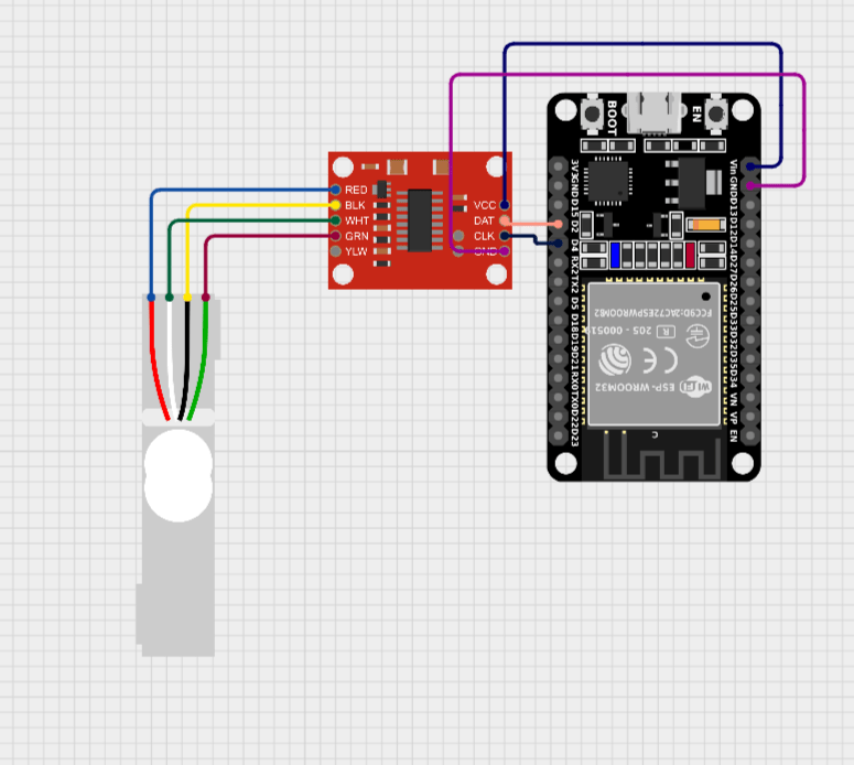
(Circuit diagram of load cell calibration)
//CODE FOR CALIBRATION OF LOAD CELL


#include <Wire.h>  // Include the Wire library for I2C communication
#include <LiquidCrystal_I2C.h>  // Include the LiquidCrystal_I2C library for the LCD display

#include "HX711.h"

#define LOADCELL_DOUT_PIN  2
#define LOADCELL_SCK_PIN   3

#define LCD_ADDRESS 0x27  // Change this to match your LCD's address

LiquidCrystal_I2C lcd(LCD_ADDRESS, 16, 2);  // Create an instance of the LCD display object

HX711 scale;

float calibration_factor = 1070640; //-7050 worked for my 440lb max scale setup

void setup() {
  Serial.begin(9600);
  lcd.begin();  // Initialize the LCD display
  lcd.backlight();  // Turn on the backlight

  Serial.println("HX711 calibration sketch");
  Serial.println("Remove all weight from scale");
  Serial.println("After readings begin, place known weight on scale");
  Serial.println("Press + or a to increase calibration factor");
  Serial.println("Press - or z to decrease calibration factor");

  scale.begin(LOADCELL_DOUT_PIN, LOADCELL_SCK_PIN);
  scale.set_scale();
  scale.tare(); //Reset the scale to 0

  long zero_factor = scale.read_average(); //Get a baseline reading
  Serial.print("Zero factor: "); //This can be used to remove the need to tare the scale. Useful in permanent scale projects.
  Serial.println(zero_factor);
}

void loop() {
  scale.set_scale(calibration_factor); //Adjust to this calibration factor

  float weight = scale.get_units() * 1000;  // Convert weight to grams

  Serial.print("Reading: ");
  Serial.print(weight, 1);
  Serial.print(" g");
  Serial.print(" calibration_factor: ");
  Serial.println(calibration_factor);

  lcd.clear();  // Clear the LCD display
  lcd.setCursor(0, 0);  // Set cursor to first row, first column
  lcd.print("Weight: ");
  lcd.print(weight, 1);
  lcd.print(" g");

  if(Serial.available()) {
    char temp = Serial.read();
    if(temp == '+' || temp == 'a')
      calibration_factor += 10;
    else if(temp == '-' || temp == 'z')
      calibration_factor -= 10;
  }
}
This obtained calibration factor when I put the second code of the load cell in and uploaded that code to esp32 then I could see the weight of the object I was placing on that load cell on the output of the serial monitor.
Then I added a 16 x 2 liquid crystal display to this circuit and made changes in the code of the load cell so that the weight readings I see on the serial monitor are readings. I will see them on the display.
Then as I wanted, whenever I was placing a weight on that load cell, I could see the weight readings properly on the LCD.
//WITH I2C DISPLAY MODULE


#define WIFI_JIO
//#include <Arduino.h>
#if defined(ESP32)
  #include <WiFi.h>
#elif defined(ESP8266)
  #include <ESP8266WiFi.h>
#endif
#include <Firebase_ESP_Client.h>

#include "time.h"


#include <Wire.h> // Include the Wire library for I2C communication
#include <LiquidCrystal_I2C.h> // Include the LiquidCrystal_I2C library
#include "HX711.h"

#define calibration_factor 1070640.00
#define LOADCELL_DOUT_PIN  16 // Connect load cell DOUT pin to GPIO21
#define LOADCELL_SCK_PIN   4  // Connect load cell SCK pin to GPIO22
#define buttonPin          2  // Pin connected to the reset button
#define resetDelay         2000 // Delay in milliseconds (2 seconds)

HX711 scale;
LiquidCrystal_I2C lcd(0x27, 16, 2); // Set the LCD address to 0x27 for a 16 chars and 2 line display
unsigned long lastButtonPressTime = 0; // Variable to store the time of the last button press

void setup() {
  Serial.begin(9600);
  lcd.begin(); // Initialize the LCD display
  lcd.backlight(); // Turn on the backlight
  lcd.setCursor(0, 0);
  lcd.print("HX711 scale demo");
  delay(2000); // Wait for 2 seconds
  lcd.clear(); // Clear the display

  scale.begin(LOADCELL_DOUT_PIN, LOADCELL_SCK_PIN);
  scale.set_scale(calibration_factor);
  scale.tare();

  pinMode(buttonPin, INPUT_PULLUP); // Set the button pin as input with internal pull-up resistor
}

void loop() {
  // Check if the button is pressed (active low)
  if (digitalRead(buttonPin) == LOW) {
    // Check if enough time has passed since the last button press
    if (millis() - lastButtonPressTime >= resetDelay) {
      // If the delay has passed, perform the reset
      ESP.restart();
    }
  } else {
    // Update the last button press time when the button is released
    lastButtonPressTime = millis();
  }

  // Display load cell readings on LCD
  lcd.setCursor(0, 0);
  lcd.print("W: ");
  lcd.print(scale.get_units() * 1000, 1);
  lcd.print(" g");
}
I studied how to add calibration and LCD from Random Nerd Tutorials website .
Link 1. https://randomnerdtutorials.com/esp32-load-cell-hx711/
Link 2. https://randomnerdtutorials.com/esp32-esp8266-i2c-lcd-arduino-ide/
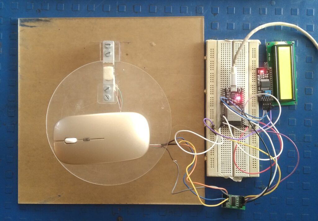
(Fig. Weighing Scale with Display)

(circuit diagram of weighing scale)
When this weighing scale is completed successfully, I want all the readings displayed on the LCD it be stored on a cloud storage.
For this I select Firebase and then I create an account in Firebase for my project. I took help from this block of random nerd tutorials to understand this firebase and create an account on it.
( Link. https://randomnerdtutorials.com/esp32-firebase-realtime-database/ )
After creating an account on Firebase I got API Key, Database URL link, Email ID and Password links. Then with the help of that tutorial and under the guidance of Suhas sir I compiled the firebase code and the weighing scale code and uploaded them properly.
Later when I was checking some weight on that weighing balance, it was uploading and saving the readings every minute in real real-time database in Firebase.
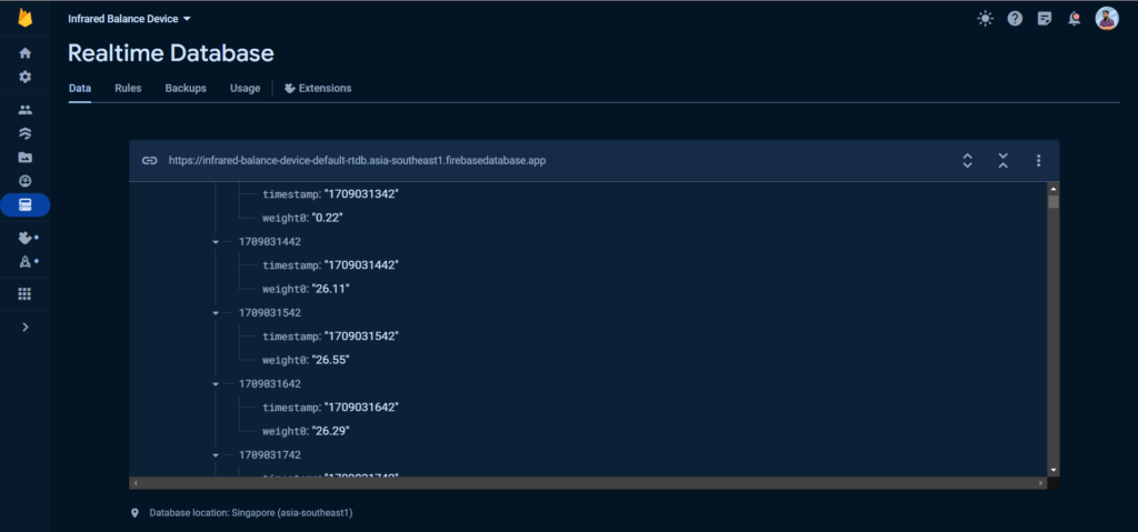
(Database storage of weighing scale readings)
 #include <Wire.h> // Include the Wire library for I2C communication
#include <LiquidCrystal_I2C.h> // Include the LiquidCrystal_I2C library
#include "HX711.h"
#define WIFI_JIO
//#include <Arduino.h>
#if defined(ESP32)
  #include <WiFi.h>
#elif defined(ESP8266)
  #include <ESP8266WiFi.h>
#endif
#include <Firebase_ESP_Client.h>

#include <Wire.h>
#include "time.h"

#define calibration_factor 1082520.00
#define LOADCELL_DOUT_PIN  16 // Connect load cell DOUT pin to GPIO21
#define LOADCELL_SCK_PIN   4  // Connect load cell SCK pin to GPIO22
#define buttonPin          2  // Pin connected to the reset button
#define resetDelay         2000 // Delay in milliseconds (2 seconds)

HX711 scale;
LiquidCrystal_I2C lcd(0x27, 16, 2); // Set the LCD address to 0x27 for a 16 chars and 2 line display
unsigned long lastButtonPressTime = 0; // Variable to store the time of the last button press
#include "addons/TokenHelper.h"
// Provide the RTDB payload printing info and other helper functions.
#include "addons/RTDBHelper.h"


// Insert your network credentials and make sure the define at the beginning of the document is correct
#if defined(WIFI_JIO)
  //#define WIFI_SSID "JioFi_10C2184"
  //#define WIFI_PASSWORD "2ycrszvn8p"
 #define WIFI_SSID "Anirudh's Galaxy M11"
  #define WIFI_PASSWORD "wxyz123456"
  #define WIFI_NAME "WS"
#endif

// Insert Firebase project API Key
#define API_KEY "AIzaSyCOIWEWCyBPaJALAvlrrXbiNyAqtlMio6w" //"va-black-soldier-flies" firebase project

// Insert Authorized Email and Corresponding Password
#define USER_EMAIL "aniruddhaifd07@gmail.com" //you can also choose: va_esp32_test@gmail.com
#define USER_PASSWORD "123456789"

// Insert RTDB URLefine the RTDB URL
#define DATABASE_URL "https://infrared-balance-device-default-rtdb.asia-southeast1.firebasedatabase.app/"

// Define Firebase objects
FirebaseData fbdo;
FirebaseAuth auth;
FirebaseConfig config;

// Variable to save USER UID
String uid;
int hours;
int minutes;

String databasePath;
String temppath = "/temperature0";
//String prespath = "/temperature1";
String humPath = "/humidity";
String timePath = "/timestamp";

// Parent Node (to be updated in every loop)
String parentPath;

int timestamp;
FirebaseJson json;

const char* ntpServer = "pool.ntp.org";

int weight;

// Timer variables (send new readings every three minutes)
unsigned long sendDataPrevMillis = 0;
unsigned long timerDelay = 60000; //1 minute delay, 1 sec = 1000 for timerDelay
//variables for actuators
unsigned long delayTime;

void initWiFi() {
  Serial.print("Connecting to ");
  Serial.println(WIFI_SSID);
  WiFi.begin(WIFI_SSID, WIFI_PASSWORD);
  Serial.print("Connecting to WiFi ..");
  while (WiFi.status() != WL_CONNECTED) {
    Serial.print('.');
    delay(1000);
  }
  Serial.print("\nConnected to WiFi!\n");
  Serial.println("IP address: ");
  Serial.println(WiFi.localIP());
  Serial.println();
}

// Function that gets current epoch time
unsigned long getTime()
{
  time_t now;
  struct tm timeinfo;
  if (!getLocalTime(&timeinfo)) {
    //Serial.println("Failed to obtain time");
    return(0);
  }
  hours = timeinfo.tm_hour;
  minutes = timeinfo.tm_min;
  time(&now);
  return now;
}


void setup() {
  initWiFi();
  //Serial.begin(9600);
  Serial.begin(115200);
  lcd.init(); // Assuming 16 columns and 2 rows
  lcd.backlight(); // Turn on the backlight
  lcd.setCursor(0, 0);
  lcd.print("HX711 scale demo");
  delay(2000); // Wait for 2 seconds
  lcd.clear(); // Clear the display


  scale.begin(LOADCELL_DOUT_PIN, LOADCELL_SCK_PIN);
  scale.set_scale(calibration_factor);
  scale.tare();
  pinMode(buttonPin, INPUT_PULLUP); // Set the button pin as input with internal pull-up resistor
  bool status;
  // default settings


  configTime(0, 0, ntpServer);

  // Assign the api key (required)
  config.api_key = API_KEY;

  // Assign the user sign in credentials
  auth.user.email = USER_EMAIL;
  auth.user.password = USER_PASSWORD;

  // Assign the RTDB URL (required)
  config.database_url = DATABASE_URL;

  Firebase.reconnectWiFi(true);
  fbdo.setResponseSize(4096);

  // Assign the callback function for the long running token generation task
  config.token_status_callback = tokenStatusCallback; //see addons/TokenHelper.h

  // Assign the maximum retry of token generation
  config.max_token_generation_retry = 5;

  // Initialize the library with the Firebase authen and config
  Firebase.begin(&config, &auth);

  // Getting the user UID might take a few seconds
  Serial.println("Getting User UID");
  while ((auth.token.uid) == "") {
    Serial.print('.');
    delay(1000);
}
uid = auth.token.uid.c_str();
  Serial.print("User UID: ");
  Serial.print(uid);

  // Update database path
  databasePath = "/UsersData/"+ uid + "/readings";

  Serial.println("\n\nEnd of void setup function");
}

void loop() {
  // Display load cell readings on LCD
//float weight = scale.get_units() * 1000;
int weight = scale.get_units() * 1000;
int weightBeforeDecimal = (int)weight;
  lcd.setCursor(0,0 );
  lcd.print("W: ");
  lcd.print(weight,0);
  lcd.print("g");
  timestamp = getTime();
  Serial.print ("current time: ");
  Serial.println (timestamp);
  Serial.println (hours);
  Serial.println (minutes);
  //Check variables and activate controls
  // Send new readings to database
  if (Firebase.ready() && (millis() - sendDataPrevMillis > timerDelay || sendDataPrevMillis == 0)){
    sendDataPrevMillis = millis();

    //Get current timestamp
    timestamp = getTime();
    Serial.print ("current time: ");
    Serial.println (timestamp);

    parentPath= databasePath + "/" + String(timestamp);

    json.set(temppath.c_str(), String(weight));
    //json.set(humPath.c_str(), String(rh));
    json.set(timePath, String(timestamp));

    //We can call that instruction inside a Serial.printf() command to print the results in the Serial Monitor at the same time the command runs.
    Serial.printf("Set json... %s\n", Firebase.RTDB.setJSON(&fbdo, parentPath.c_str(), &json) ? "ok" : fbdo.errorReason().c_str());
  }


}
After this successful attempt, I studied how these readings would look on a webpage and with the help of this tutorial I decided to create them using Webpage Visual Studio. For this web page, I copied the important Firebase configuration from Firebase and uploaded it to the code in Visual Studio when I successfully deployed this code, the web page was created.
After that, whenever I placed a weight on this weighing balance, the readings of the weight were stored in the Firebase database and at the same time, the weight was displayed on the web page
( Link. https://randomnerdtutorials.com/esp32-firebase-web-app/ )
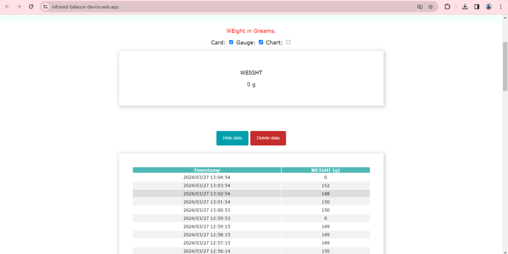
(Web page of readings of weighing scale)
3/3/2024
When Mr. Dikshit Sir took an overview of this project with me, he explained the mistake made by and made me understand How much and why is it necessary to use a known weight to calibrate the load cell, (Known weights are used for load cell calibration to ensure its accuracy and reliability by comparing the output signal to expected values, helping to confirm its performance and suitability for measuring weight or force accurately.) and at the same time, Mr. Dikshit Sir explained to me how exactly the Infrared Lamp works. (An infrared lamp works by emitting infrared radiation, which is a type of electromagnetic radiation with longer wavelengths than visible light. When the lamp is turned on, it heats a filament or element inside, which then emits infrared light. This light is sensed by the skin and other surfaces, producing heat)
And further in this circuit I decided to add a relay module to connect the IR lamp.
But by mistake, I gave a power supply of 12 volts instead of 5 volts in this circuit and due to this the ESP 32 in this circuit was damaged.
After that, I changed the esp and checked if each component was working properly, so I checked if each component started properly and after uploading the code it worked properly.
After that, I started again from calibration, calibrated the load cell, then added the LCD and linked it back to the Firebase. Since I had all this code saved, I didn’t have much trouble following these steps.
7/3/2024
When I discussed this project with Dikshit Sir, he explained to me about heat transfer and explained the types of heat transfer.
(Heat transfer is the movement of thermal energy from one object or substance to another due to a temperature difference. There are three main types of heat transfer:
1. Conduction: This occurs when heat energy is transferred through direct contact between particles of a substance.
2. Convection: This involves the transfer of heat through the movement of fluids (liquids or gases). Convection can occur naturally.
3. Radiation: Radiation is the transfer of heat energy through electromagnetic waves. Unlike conduction and convection, radiation does not require a medium to propagate and can occur in a vacuum.)
At the same time, Sir told me that the temperature in the Infrared balance device is between 100⁰ to 105⁰ C and when the temperature goes beyond 105⁰ C, the device should automatically turn off.
26/03/2024
I successfully tried to write code to add a relay module to my circuit. My goal was to program the relay module to automatically turn off when the weighing balance reads a constant of 3. Although I have referred some code examples, I am not able to get the expected output. Despite being able to turn on the relay module with the help of the code, it did not turn off even after saving 3 readings.
Later, I had to switch from my computer to my laptop. After downloading the Arduino IDE software and installing the necessary libraries and ESP 32 board related to my project, I encountered problems related to ports. When I selected the port to upload the program it was not being selected. After researching the problem, I downloaded the CP210 Windows drivers for the ESP and installed them properly.
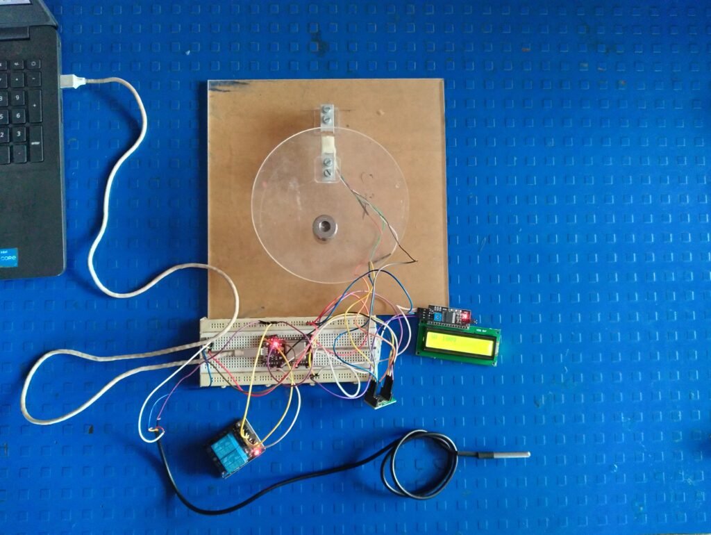
After installing the port, I was able to select the port and upload my old code to the ESP in my circuit. The circuit started working and every minute all the weight readings were stored in the Firebase real-time database system.
However, I am still facing challenges in programming the relay module to automatically turn off after 3 continuous readings. I believe this will be resolved soon.
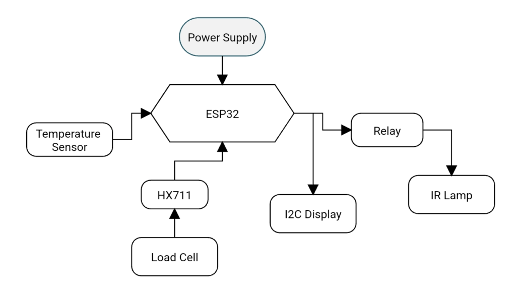
(Flowchart Of Infrared Moisture Balance Device System)
12/04/2024
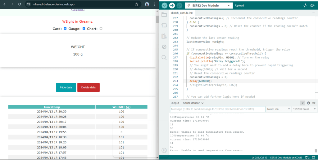
Today, first I tried a practical demonstration of a relay module, and it was successful. Later I took the help of Suhas sir to build the logic for the relay module, I wanted such a logic so that when these 3 readings are stored the same, the relay should automatically turn off. At first, we had difficulty in validating the logic but after some attempts, it successfully built the logic, and during the demonstration when 3 readings were the same the relay turned off.
After this, I took the Temperature sensor (ds18b20) in the circuit and also tried a practical demo on it so that I could understand the Temperature sensor. After this successful demo I took to build the logic for the temperature sensor, in that logic I saw that whenever the temperature crosses a limit, the relay turns off automatically, after some effort I got that logic and I mixed it into this program.
After completing this programming part, I tested this circuit properly. This testing was completed successfully, the readings of the weight I wanted were stored in the firebase and at the same time they were visible on the web page. And when 3 readings came constant then that relay turned OFF and simultaneously when the temperature went beyond 40⁰ C that relay turned OFF.
( Link for Relay Module tutorial : https://randomnerdtutorials.com/esp32-relay-module-ac-web-server/
Link for Temperature Sensor tutorial : https://randomnerdtutorials.com/esp32-ds18b20-temperature-arduino-ide/ )
14/04/2024
Today first I drew a circuit diagram of my project circuit with the help of the diagram I soldered each component on general purpose PCB. After the soldering work, I did the circuit test again and this testing was completed successfully.


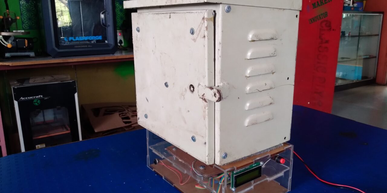
After completing the electronic circuit part of the project, I moved on to the second part which involved designing the casing for the Infrared moisture balance device.
I created rough drawings for two different types of casing and showed them to Prasad sir, we discussed both of those designs and I understood that one of my designs was suitable for the casing. Based on our discussion, we finalized the design.
During a discussion with Dixit sir, we talked about the material for the casing. From that discussion, it was decided to use an Acrylic sheet for the outer casing. We also realized that insulation was necessary for the casing to function properly at a specific temperature beyond 100⁰ C. Then I started looking for an insulation sheet that would suit that temperature.
Prasad sir asked to measure the thickness of the insulation sheet we are going to use, and I am currently studying of Thickness of Insulation sheet.
Insulation Sheet Material Studied by Me:
- XLPE Sheet: (Cross linked polyethylene)
It helps maintain temperature stability and protects temperature-sensitive items from extreme heat or cold during storage or transportation. This feature is particularly useful for products that require temperature control, such as food, pharmaceuticals, and electronics.
- Fiberglass:
Fiberglass insulation is generally unsuitable for food-grade processes due to the risk of contamination from its potential to shed tiny glass fibers, compromising food safety standards. Industries requiring stringent hygiene, such as food processing or pharmaceuticals, prefer insulation materials specifically designed to meet these standards, often opting for non-fibrous and non-particulate materials like stainless steel or food-grade plastics to ensure compatibility with regulatory requirements and the preservation of product integrity.
- Polyurethane:
PU helps preserve food
The PU sandwiched between the insulation layers of various parts of refrigeration and freezing equipment can keep out the ambient temperature and ensures the freshness and safety of food.
- Elastomeric insulation:
Elastomeric insulation is not typically recommended for direct contact with food due to potential health and safety concerns. While it is versatile and durable for industrial and mechanical applications, it is not specifically designed or certified for food-contact use. When it comes to materials for food-related purposes, it’s essential to choose options that meet specific food safety standards and regulations to ensure the protection of consumers. Materials approved for food contact are subject to rigorous testing and regulations to prevent any contamination or health risks. Therefore, when considering insulation materials for applications involving food processing or storage, it’s best to consult with experts or use materials explicitly designed and certified for such purposes.
- Phenolic Insulation:
Phenolic foam, when used in composite panels for food processing facilities, is designed to meet stringent hygiene standards. These panels typically feature steel facings on both sides of the foam core, providing a durable and easy-to-clean surface suitable for food-related environments. Additionally, phenolic foam’s resistance to moisture and mold growth further enhances its suitability for use in food processing areas. However, it’s essential to ensure that the specific phenolic foam product used complies with relevant food safety regulations and standards to guarantee its suitability for contact with food products
| Material | Temp (degree C.) | Thickness (mm) | Cost |
| XLPE Sheet | 120 | 6 to 15 | 225 (sq. m) |
| Fiberglass | 540 | 1.2 to 10 | 250 (sq. m) |
| Polyurethane | 120 | 1.5 to 3 | 200 (sq. ft.) |
| Phenolic | 150 | 15 to 50 | 485 (sq. m) |
Difference of Insulations Sheets:
| Parameter | Phenolic Insulation Sheet | Fiberglass Insulation | Polyurethane Foam | XLPE Sheet |
| Safety | Is generally considered safe for food-grade applications as it does not off-gas harmful chemicals. | It can release tiny fibers that may pose a health risk if ingested, making it less ideal for direct food contact applications. | It can be food-safe if it meets specific regulatory standards and is formulated without harmful additives. | Is considered safe for food contact applications as it does not contain harmful chemicals and does not leach into food. |
| Cleanliness | It has a smooth surface that is easy to clean and maintain, making it suitable for food environments where cleanliness is critical. | It can trap dust and particles, potentially leading to contamination in food environments. | It can be easy to clean but may deteriorate over time if exposed to certain chemicals or cleaning agents. | It has a smooth surface that is easy to clean and maintain, making it suitable for food-grade environments. |
| Durability | Is durable and resistant to moisture, which is beneficial in food processing environments where sanitation is key. | It is may degrade over time when exposed to moisture, reducing its effectiveness in food-grade applications. | Is generally durable and resistant to moisture, making it suitable for food-grade applications if properly sealed. | Is durable and resistant to moisture, chemicals, and corrosion, making it ideal for food processing and storage applications. |
| Compliance | It can meet food safety regulations depending on the specific product and manufacturer. | It is may not meet strict food safety regulations due to the risk of fiber release. | Is generally durable and resistant to moisture, making it suitable for food-grade applications if properly sealed. | It can meet food safety regulations and is often used in direct food contact applications due to its safety and durability. |
- Conclusion from difference:
When considering materials for food-grade applications, phenolic insulation and XLPE sheets emerge as preferable options owing to their inherent safety, cleanliness, and durability features.
05/05/2024
When I discussed with Dixit sir about insulation and its thickness, I decided to use a Phenolic Insulation sheet as per sir’s advice and we decided on its thickness as below.
In that, we first measured the surface area of the Box.
(SA)= 2 × ((lw)+(lh)+(hw))
(SA)= 2 × ((0.2 × 0.2) + (0.2 × 0.35) + (0.35 × 0.2))
(SA)= 0.36 m
After that, we measured the thickness of the insulation.
t = (K × A × ΔT) / Q
Where,
Thermal conductivity (K) = 0.018 W/m.k
Surface area (A) = 0.36 m²
The amount of heat (Q) = 23
Temperature difference (ΔT) = T1 – T2
= 105⁰C – 35⁰C
= 70⁰C
t = Thickness of Insulation = ?
Now,
t = (0.018 W/m.k × 0.36m² × 70⁰C)/23
t = 0.019 m
t = 19.72 mm
So required thickness for Phenolic Insulation is 19.72 mm.
07/05/2024
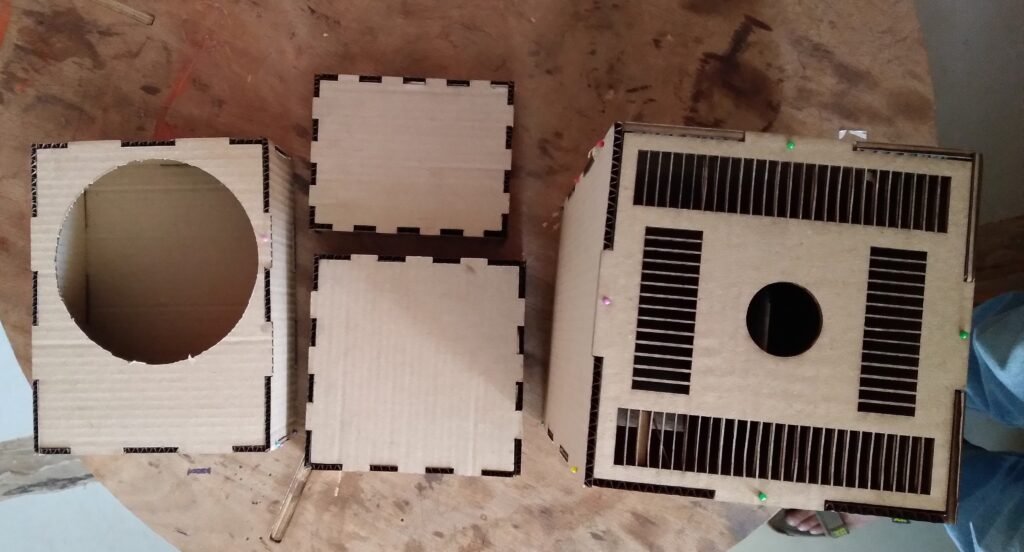
After all this discussion and calculation I decided to make a trial prototype using a board.
I created the complete design on R D Works software. With the help of the Leaser Cutter machine, I cut the cardboard and after that, I made my trial prototype from the cut cardboard piece.
When I showed this designed design to Prasad sir and Dixit sir, on their advice I completed the trial prototype by making some changes as suggested by sir in that design.


08/05/2024
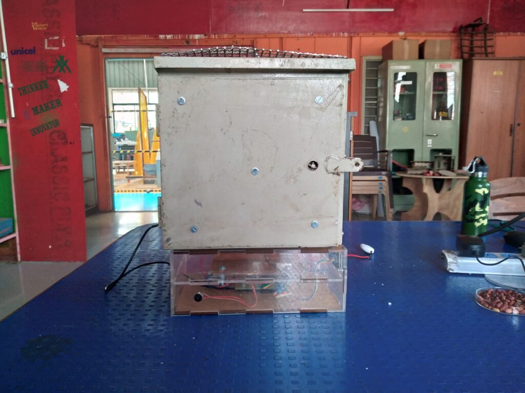
With the prototype finalized, I proceeded to create a bill of materials outlining all the electronic components and hardware materials necessary for the project’s completion. The bill of materials is presented as follows:
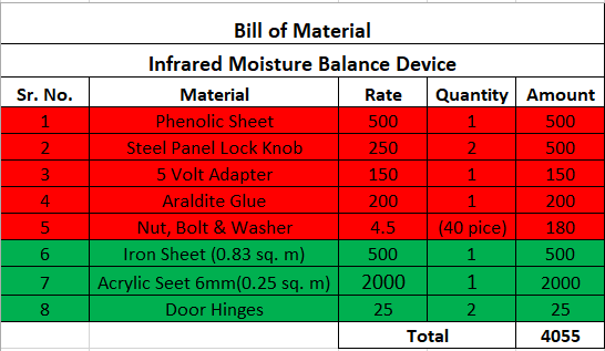
The total cost of the project, including electronics components and hardware material, amounts to INR 6,453 RS.
I went to the market to get the material as planned, but I couldn’t find the phenolic sheet. After checking in several shops, it became clear that the phenolic sheet was not available. I discussed this with Prasad Saron and decided to buy an XLPE sheet instead.
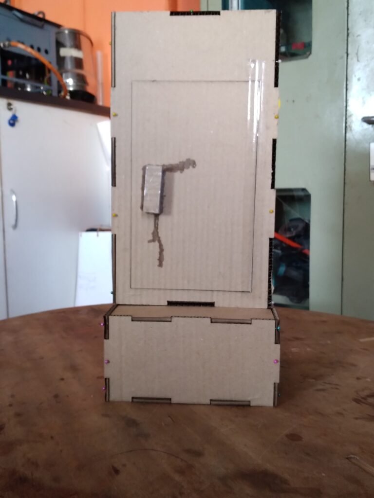
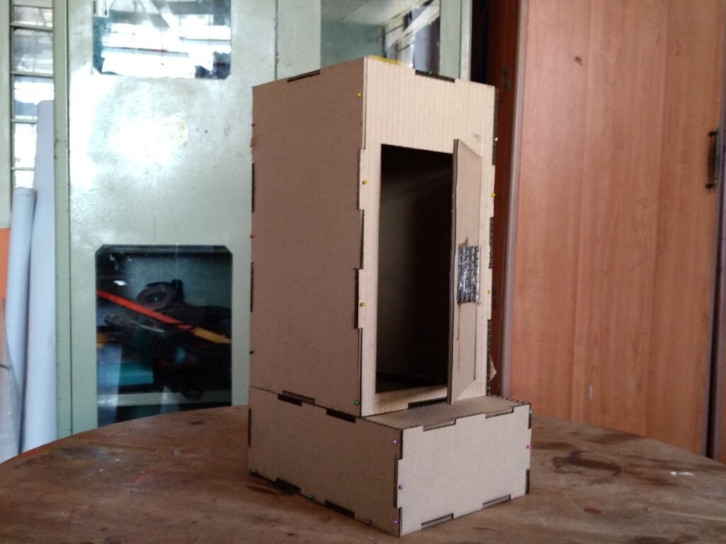
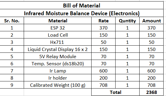
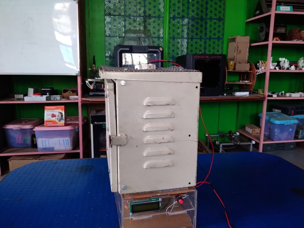
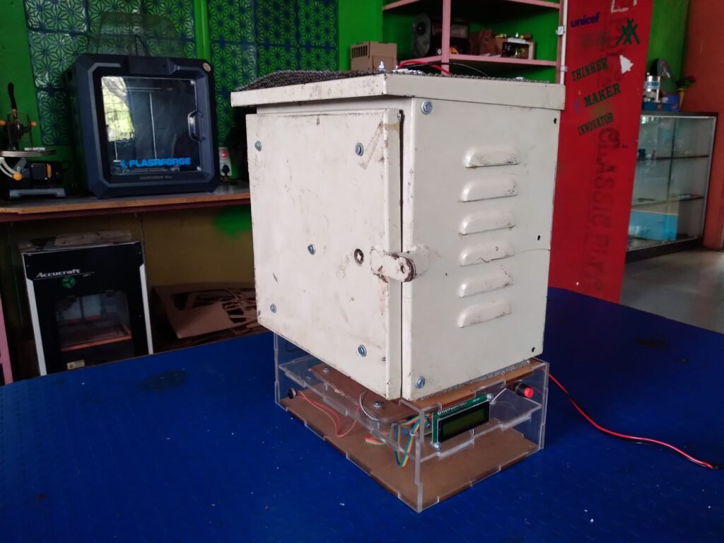
When I started working on making the casing, I encountered some problems. Prasad sir suggested getting a metal box from the scrap yard. After selecting the box and taking its dimensions, I made some design changes and started working on the casing. Since I lacked knowledge in this area, I sought help from Mr. Bhushan Rothe and Mr. Siddhant Said, as well as a student from DBRT Mr. Soham, help me to design and create the acrylic box.
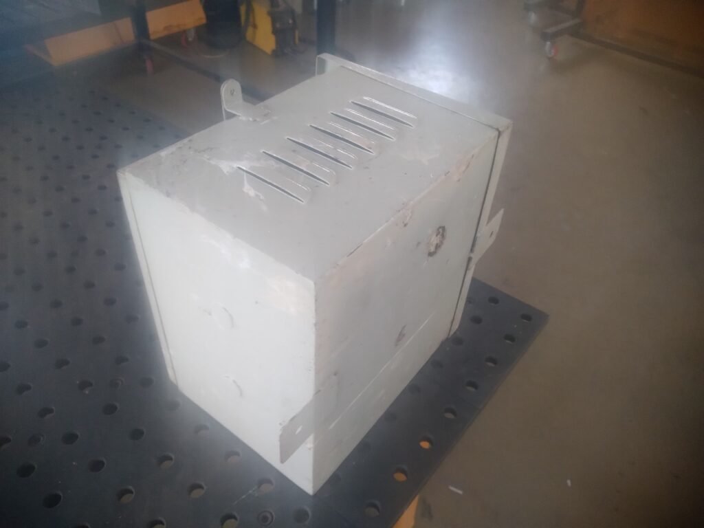


We marked and cut the casing, and then used HotBond glue to properly attach the insulation sheet. After that, we placed an iron plate on it to ensure long-term insulation. A lamp holder was then installed on the metal case, and mesh was applied to it.
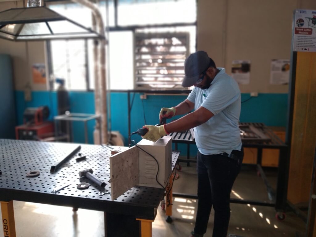
After completing the metal casing, we arranged the electronic circuit and the prepared weighing scale inside the acrylic box. Then, we joined both boxes together to create the prototype. After completing this, I put it for testing.
Testing Result: When I first started testing this device, the initial 2 to 3 readings were accurate, but later on, there was a significant change in the readings. Upon researching, I discovered that the load cell was not providing accurate readings once the temperature exceeded 60 degrees Celsius.
Arduino Full Code Of Project :
The Problem I Face During This Project And What Changes Is Required According To Me:
https://vadic.vigyanashram.blog/wp-content/uploads/2024/05/Problem-I-Faced-2.pdf


