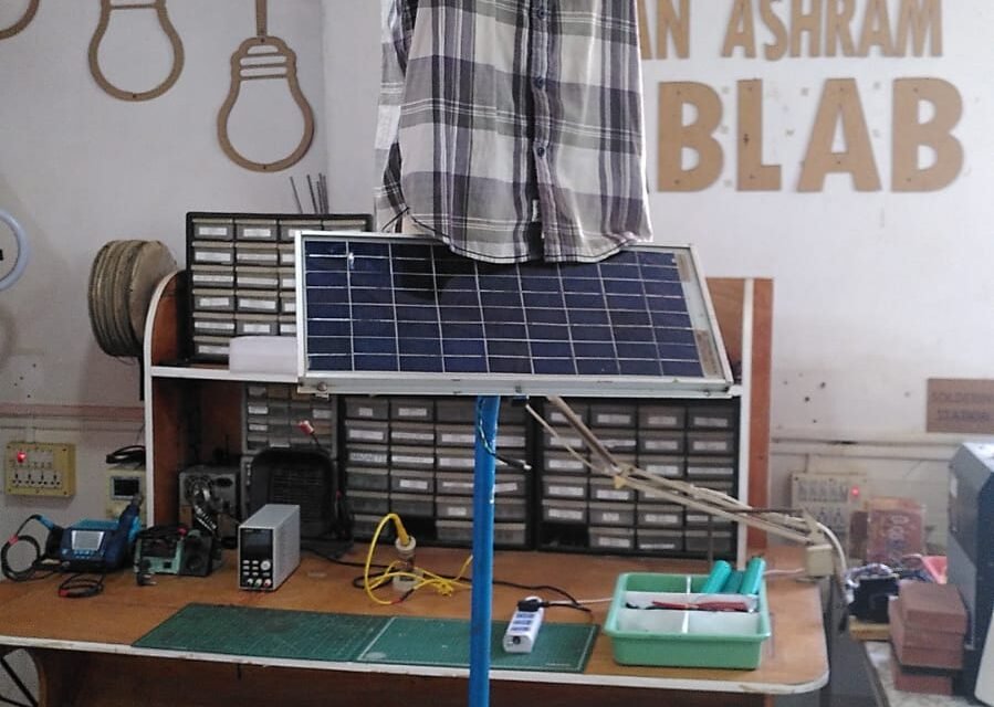
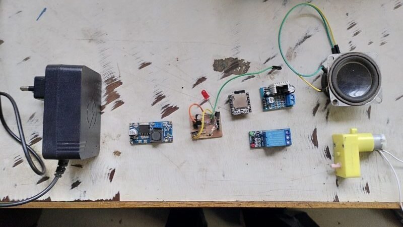
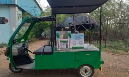
Resultat final
Introduction :
Le but est de realiser un produit finis pour le projet pour ca il faut realiser un pcb avec toutes les caracteristique identifier precedement (music et mouvement dans des temps definis)

Timer choice and reflexion
Apres different test l’utilisation du TIMER NE555 n’a pas ete concluante, les intervales de temps etant different des intervales theorique. La solution que je pense la plus probable etant la longueur des intervales (valeur des resistance ~1-10 MOhm) etant trop haute pour la resistance interne du timer (Je pense que le module doit pouvoir etre implementer mais j’etais a court d’idee). C’est pourquoi je me suis tourner vers un autre module : le module qui est un 14-Stage Binary Counter
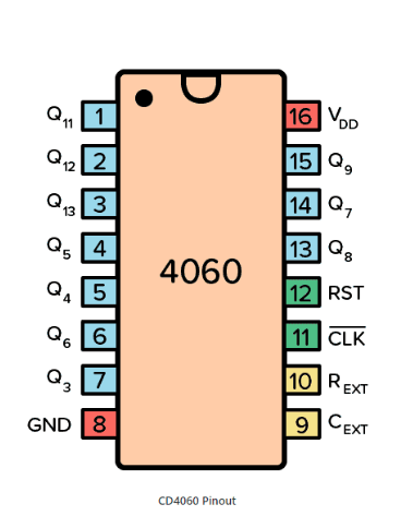
Le fonctionnemenet est assez facile, il cree emet un tick a une frequence determiner par les resistance et capacite (C1 R1 R2) comme explique dans cette article. Par exemple avec la formule Frequency f (Hz) = 1 / ( 2.3 * Ct * Rt ) et avec Ct = C1 = 100uF = 10^-4 , Rt = R1 = 50kOhm = 5 *10^4 on obtient F = 1 / (2.3*5) = 0.1 Hz .
Ensuite chacun des pin Q1,Q2, …,Qn,… Q13 sont active tous les 2^n tick donc pour Q4 par exemple il est actif pour 2^4*f pour 2^4*f seconde.
Application du timer au projet
Dans un second notre but est d’utiliser ce timer pour activer le mouvement et la musique. Qui on chacun des particularites propres
Pour le mouvement nous voulons active un relays pendant ~20s et le laisser off pendant ~10 min pendant 20s nous voulons un sortie HIGH pour activer le relay
Pour le son nous voulons lancer un son pendant ~30s puis attendre pendant une 20 ene de minutes, nous voulons un flanc descandant pour active le pin du module MP3
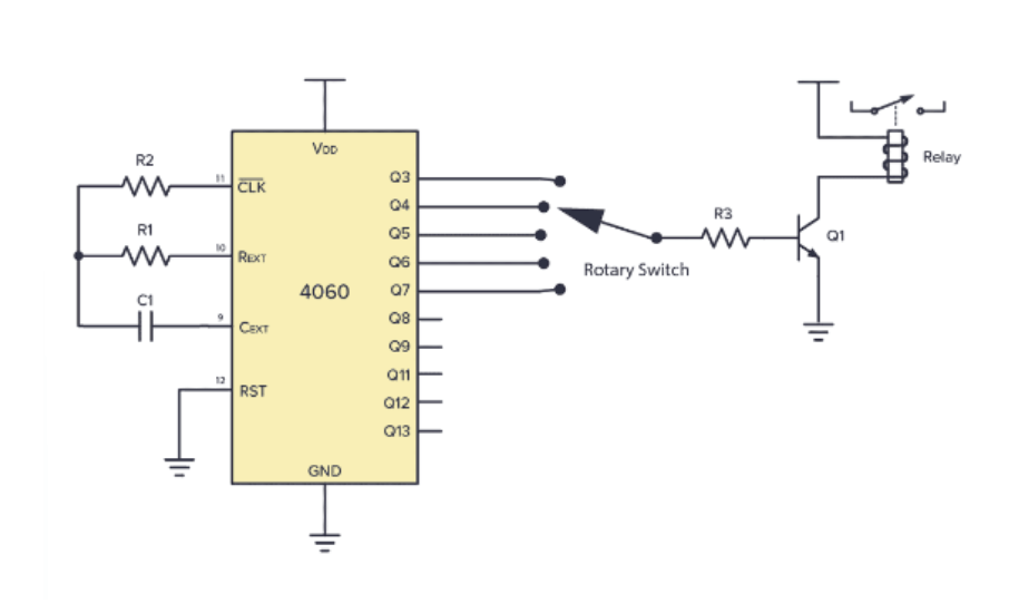
Pour cela cela veut dire que nous avons besoin de generer different type de temps precis pour cela, une solution possible est d’utiliser une porte AND prenant en entree deux sortie du counter (ex q4 et q11) et permettant de reset le counteur et de relie l’element a la porte q11.
Comment ca marche : lorsque Q11 est active (soit tous les 2^11*f) il va etre haut tant que Q4 ne sera pas High (soit pendant 2^4*f) , quand Q4 sera HIGH both et QQ seront HIGH donc la connecion de la porte AND sera HIGH et le reset sera active.
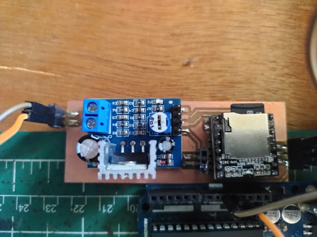
Fonctiomment du module mp 3
Tuto : https://www.youtube.com/watch?v=2LbxvdOA4zM
Datasheet https://dlnmh9ip6v2uc.cloudfront.net/datasheets/Widgets/WTV020SD.pdf (check if good)
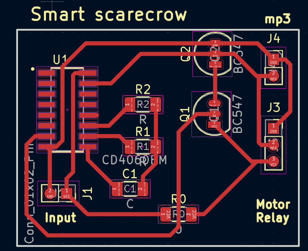
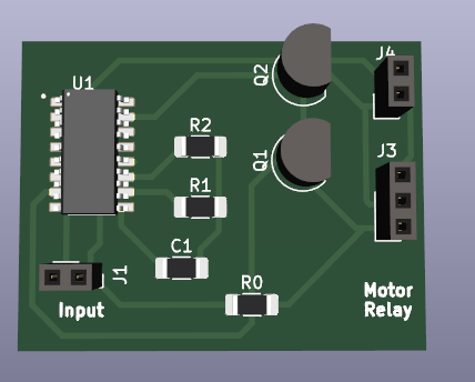
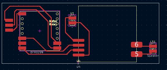
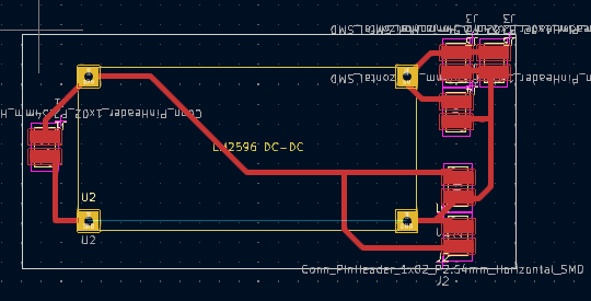
Projet final
Final PCB (never printed)
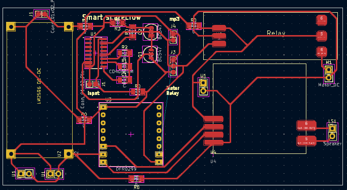
Electrical circuit
Part 3 Price Comparison:
Old version material cost :
| Old version | |
| Music | 650 Rs |
| Timer | 250 Rs |
| Total | 900 Rs |
New version material cost (including PCB):
| New version | |
| MP3 module | 100 Rs |
| Amplifier | 95 Rs |
| 14 Binary counter | |
| NPN transistor *2 | |
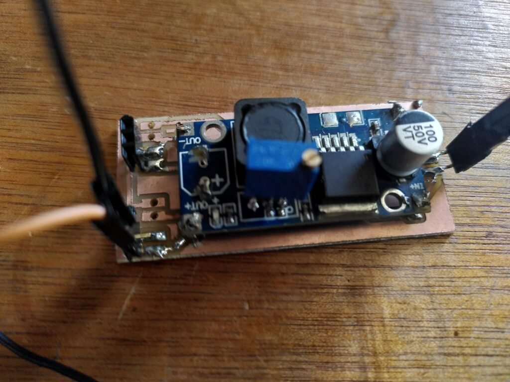
| DC DC buck converter | |
| Relay | 55 Rs |
| Resistor *2 | 10 Rs |
| Capacitor | 15 Rs |
| Total | 294 Rs (195+99) |
This results in savings of X Rs.
Here’s a list of the necessary components with their names, prices, quantity, and supplier links:
| New version | Price | Quantity | Supplier link |
| MP3 module | 100 Rs | 1 | https://robu.in/product/mp3-tf-16p-mp3-disk-tf-card-module-serial-port/ |
| Amplifier | 95 Rs | 1 | https://robu.in/product/tda2030a-6-12v-18w-audio-amplifier-module/ |
| 14 – Binary counter | 1 | https://robu.in/product/cd74hc4060m96-14-stage-binary-counter-with-oscillator-smd-soic-16-tex | |
| NPN transistor | 2 | ||
| Relay | 55 Rs | 1 | https://robu.in/product/12v-1-channel-relay-module/ |
| DC motor | 1 | ||
| Resistor (9MOhm & 1MOhm) | 5/5 Rs | 1/1 | https://robu.in/product/10m-ohm-1-4w-0603-surface-mount-chip-resistor-pack-of-100/ https://robu.in/product/1m-ohm-1-4w-0603-surface-mount-chip-resistor-pack-of-100/ |
| Capacitor | 15 Rs | 1 | https://robu.in/product/1000uf-25v-electrolytic-capacitor-dip-pack-of-5/ |
| DC DC buck converter | 1 | ||
| Switch on/off | 1 | ||
| Pcb itself | 1 | ||
| Speaker | 1 | ||
| Total PCB | 1 | ||
| Solar panel | 1 | ||
| Battery | 1 | ||
| Structure | 1 | ||
| Total |
Version Microcontroler
There are still issues with the timer, so in the meantime, any microcontroller can be used, such as an Arduino Nano. Three pins are required: one for the music, one for the motor (mosfet or relay), and one for a button to activate everything directly.
// Pin configuration for the devices
const int pinMotor = 2;  // Motor activation every 30 minutes for 20 seconds
const int pinMusic = 3;  // Music with falling edge every 20 minutes
const int pinButton = 4;  // Button to manually activate the motor and music

// Timing variables
unsigned long previousMillisMotor = 0;
unsigned long previousMillisMusic = 0;
const long intervalMotor = 30 *60 * 1000;  // 30 minutes converted to milliseconds
const long durationMotor = 20 * 1000;  // 20 seconds converted to milliseconds
const long intervalMusic = 20 *60 * 1000;  // 20 minutes converted to milliseconds

// State variables for the motor, music, button, and power
boolean motorState = LOW;  // LOW if using a relay, HIGH if using a transistor
boolean musicState = LOW;  // HIGH if using a relay, LOW if using a transistor
boolean buttonState = LOW;

void setup() {
  // Initialize the pins
  pinMode(pinMotor, OUTPUT);
  pinMode(pinMusic, OUTPUT);
  pinMode(pinButton, INPUT_PULLUP);  // Use internal pull-up resistor to avoid external resistor

  // Deactivate the motor and music at startup
  digitalWrite(pinMotor, LOW);  // HIGH if using a relay
  digitalWrite(pinMusic, HIGH);  // LOW if using a relay
}

void loop() {
  // Check the state of the button
  buttonState = digitalRead(pinButton);

  // Check if the motor interval is reached
  unsigned long currentMillis = millis();
  if (currentMillis - previousMillisMotor >= intervalMotor) {
    previousMillisMotor = currentMillis;

    // Activate the motor for the specified duration
    motorState = HIGH;  // LOW if using a relay
    digitalWrite(pinMotor, motorState);
    delay(durationMotor);
    motorState = LOW;  // HIGH if using a relay
    digitalWrite(pinMotor, motorState);
  }

  // Check if the music interval is reached
  if (currentMillis - previousMillisMusic >= intervalMusic) {
    previousMillisMusic = currentMillis;

    // Activate the music with a falling edge
    digitalWrite(pinMusic, LOW);
    delay(100);
    digitalWrite(pinMusic, HIGH);
    delay(100);
    digitalWrite(pinMusic, LOW);
    delay(100);
    digitalWrite(pinMusic, HIGH);
  }
}

// Function to manually activate the motor and music and reset the timing
void activateDevices() {
  // Reset the timing
  previousMillisMotor = millis();
  previousMillisMusic = millis();

  // Activate the motor and music
  motorState = HIGH;  // LOW if using a relay
  musicState = LOW;
  digitalWrite(pinMotor, motorState);
  digitalWrite(pinMusic, musicState);

  // Wait for the button to be released
  while (digitalRead(pinButton) == LOW) {
    delay(10);
  }

  // Deactivate the motor and music after the button is released
  motorState = LOW;  // HIGH if using a relay
  musicState = HIGH;
  digitalWrite(pinMotor, motorState);
  digitalWrite(pinMusic, musicState);
}
- Pin Configuration (Lines 2-4): Defines the pin numbers for the motor, music, and the button.
- Timing Variables (Lines 6-11): Sets up variables to manage timing intervals for motor activation, music falling edge, and button debouncing.
- State Variables (Lines 13-15): Boolean variables to store the current state of the motor, music, and the button.
- Setup Function (Lines 17-27): Initializes the pins, sets the initial state of the motor and music, and configures the button with an internal pull-up resistor.
- Loop Function (Lines 29-54): Checks the button state and activates the motor and music based on timing intervals. The music activation includes a falling edge pattern.
- Activate Devices Function (Lines 56-75): A function to manually activate the motor and music, resetting the timing and deactivating them after the button is released. It also includes comments about relay states.


