25 Oct 2023
Intoduction/ Background :-
The BSF project is to develop and implement technology for retrieving food value from biodegradable waste and an eco-friendly way for wet waste management. A sub-project is being undertaken to develop a machine that can separate the BSF Larvae and remaining kitchen waste effectively. The project is about separating BSF Larvae from the complete or partially composted kitchen waste aided by BSFL. The BSFL thus separated can serve as poultry feed or fish feed. The separation can be achieved by using the multiple vibrating screens provided with different outlets, managing the moisture content can be a trick for separation. Understanding the natural tendency of BSFL can open up new avenues.
Objectives of Project :-
1)Reduce time consumption. 2)To separate the BSF Larvae from the kitchen waste. 3)Effectively separate the waste and larvae with high efficiency.
The project of the BSF Larvae separator machine was assigned to me by Dixit sir and Mahesh sir after the project was assigned to me some discussions were held with Dixit sir and Mahesh sir in those discussions they explained to me more details about the project and gave an idea and scale of the project on which I had to work.
After those initial discussions, I started to read some documents about BSF Larvae and I also read a separation machine design and evaluation procedure and other detailed information.
The documents and the pdf which I read there links are provided below:-
https://vadic.vigyanashram.blog/wp-content/uploads/2023/10/Black-Soldier-Fly.pdf
I made some online market surveys on the BSF Larvae separation machine *Points covered in the survey:- The method of separation. The separation capacity of the machine. The Efficiency of the Separation Machine. The price of the machine. Market availability.
The output of the market survey is that I get that the most used method for the separation of BSF Larvae is by using the screens provided with the vibration, the separation capacity of available machines varies between 40 to 70 kg/hr of BSF Larvae from the frass of about 200 to 300 kg, the efficiency of separation machine is around 90%. The price of a separation machine starts from Rs.50,000 and it can be up to Rs.1,50,000 according to its separation capacity.
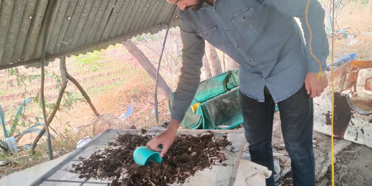
To understand the problems of separation I did some BSF Larvae separation work on the ashram’s separation unit


Problems identified in separation work are that it is time-consuming, requires sunlight, separation is done in small quantities, breaks the clods manually, and requires labor.
04//11/23
We gathered for a meeting to discuss the BSF Larvae separation project with a few DIC members in that meeting I presented some of my ideas on the BSF Larvae separation machine.


Moisture Content in kitchen waste


23/11/23
After the Diwali holidays, we had some discussions on the different separation ideas and techniques. The separation models that we discussed are rotary screen separation, vibrating screen separation, separation through artificial light, separation using Bussa, and separation by water. In that discussion, we identified some advantages, disadvantages, and benefits of each separation idea from the discussion Dixit sir told me to fabricate some small models on which I had to take trials.
In the ashram we have a gravel separation unit that was not in use dixit sir told me to repair and modify that model as a rotary separator for taking the trials.
24/11/23


The condition of the structure was good only the work needed to be done was in the middle section of the model. The middle section is in poor condition, we removed the middle section assembly from the machine and after that removed the sieve which is surrounded by a circular portion. After that, we identified the damaged bars and iron strips and cut them from the circular frame.
After cutting down damaged components and analyzing the remaining frame we made a list of materials required for the fabrication.
25/11/23
List of material
6×6 sq mm sieve
Washer = 100
10 mm bar = 1
Welding rod 2.5 mm = 1 box
Drill bit 3.37 mm = 1
Then we purchased the material after purchasing we started the fabrication work. Firstly we cut the bar with proper measurements.

After that, we weld the bars on the frame

Then we placed the 6×6 sq mm sieve over the fabricated frame and fixed it by drilling holes and placing the rivet with a washer into the holes at some places we tied the sieve to frame with the wire.

1/12/23
After this, we fixed this fabricated frame back to its place on the main frame and set the machine for the trail beside the shed.


After the setup, we are ready to take the trial
1/12/23
Trial 1:-
Compost used for separation:- 12 kg
Sieve size:- 6×6 sq mm
RPM:- 30
length of sieve:- 5 ft
Diameter of sieve circle:- 1.8 ft


Outcomes of trial:-
*Efficiency of separation is very poor only 30 to 40% of larvae were separated from the compost.
*Only smaller-sized larvae were separated from the compost.
*clods present in the compost were broken down into smaller sizes.
*Feeding from the hopper is not working properly.
*compost needed to be pushed downside by a stick to fall down in the separation unit.
02/12/23
After this Dixit sir, Mahesh sir, and I discussed the Outcomes of the first trial from that discussion we learned that we require a sieve of a larger size than the existing one, from the discussion we decided to buy a sieve of 10×10 sq mm of hole size.
Then I did a market survey for a sieve of 10×10 sq mm size, I contacted all the hardware shops near the Pabal and in Shikrapur and I got to know that the sieve of the size that we required was not available in these shops then we decided to buy the sieve from the Pune market
04/12/23
After this, we removed the sieve used for the first trial and then fixed the new sieve on the separation machine.

05/12/23
After this, the machine was ready to take the second trial with a changed sieve size
Trial 2:-
Compost used for separation:- 20 kg
Sieve size:- 10×10 sq mm
RPM:- 30
length of sieve:- 5 ft
Diameter of sieve circle:- 1.8 ft
Outcomes of Trial:-
*Efficiency of the larvae separation is very high about 85 to 90 percent of larvae get separated from the waste compost.
*Small-size compost particles and sticks are still present in some amount in between separated larvae.
07/12/23
After the result of the second trial, we have a brain-solving meeting to solve the problems and do ideation on the problems. In that meeting, we mainly discussed the types of feeding, feed rate, sieve, inclination, and RPM.

To maintain and regulate the feed rate we listed five ideas:-
- Worm Gear
2. Water Wheel.
3. Conveyor.
4.Ram Feeding.
5. Oscillating Hopper.
From the discussion, we considered that the required RPM for better separation should be 20 to 30 RPM. By conducting further trials we will confirm the actual required RPM for effective separation
After that discussion, Prasad sir told me to draw an engineering design for the model that we are going to fabricate to take further trials and give me the strength of the material that we are going to use for fabrication.


16/12/23
After that we had Dixit sir make some conversation with Dasnurkar sir. Firstly dixit sir described the BSFL project and the trial outputs in short to Dasnurkar sir then after that he guided us in the next trial model, the specification, the material strength, and what should be the diameter, and length of the cylinder and other small things like the circle of the cylinder should be the perfect round, etc.
18/12/23
After that conversation, they sent some dimensions for the model and shared some information about the Trommel screen through email.
19/12/23
We had another small brain-solving session in that session we discussed the RPM of the separation cylinder because we are fabricating this model for trial purposes we didn’t want to make so much expense on it which is why we ideat some RPM reduction techniques to have less expensive RPM reduction component.
In that session, we ideated techniques such as chain sprockets, notch wheels, water wheels, and wooden wheels. We decided to try the wooden wheel.
Then Prasad sir told me to make a bill of material for fabrication. after making the bill of material we identified that we have some material in our scrap that can be utilized for the fabrication of the separation model, the model is for trial purposes therefore we made some changes according to the material readily available to us.
To design the gear, firstly I calculated the gear teeth ratio
In this, the driver gear RPM will be given by the hand that’s why assumed
N1=60 RPM
We wanted RPM about 20 so I took
N2=20 RPM
I took T2=30 teeth
Speed Ratio= N1/N2=T2/T1
=60/20=30/?
T1=10
Gear teeth ratio=30/10
=3:1
21/12/23
After that, I brought the remaining fabrication material and started the fabrication work.
Firstly I cut down the spocks of bicycle rims.


After that, I tied the ms bar of 8mm from the outer side of the rims and welded the rims with the ms bar.

22/12/23
After that, I went to the village the turning the GI pipe, and then I fixed the bearing into that GI pipe.

After that, I cut the bar and we welded the bar to the GI pipe and outer bar. The bar is placed between the cylinder.
Then I surrounded the sieve of 4×4 sq mm on the fabricated cylinder.

After that, I designed the two gears with a diameter of a driver is 21cm and a driven is 7cm. Then I cut it on a laser cutter then showed Prasad sir he said that the strength of the gears looked weak so redesigned it by taking the greater diameter and keeping the module of gears the same.
27/12/23
After that, I designed the gear and cut them first with a laser cutter discussed with thee prasad sir, and then cut the gears on the wood router machine

28/12/23
Cutting of Gears on Wood Router machine


some of the teeth of the gears were not cut well so I did some filelling and finishing work.
Alternately I talk to Mahesh sir about further base structure fabrication work. I have drawn a drawing of the base structure.

Then I showed this drawing to Dixit sir and Mahesh sir and they told me for some changes and told me for an engineering drawing
Engineering drawing of the structure

Then I showed the drawing to Mahesh sir and Prasad sir And they told me that the distance between the gear and the cylinder was too small so we decided to mount the gear on the outside portion.
S.V of the structure with all the dimensions near the gear and cylinder head section

Slope calculations
Then I made the bill of material and we used the scrab material for the structure fabrication
Then I cut the scrab material and started the fabrication

05/01/24
Then I took the trial of the gears by mounting them on a temporary shaft and fixed the shaft in the bearings. the bearings were fixed on the benchvoice.
After the trial, I created the slot on the shaft for fixing gears on it, and I assembled the hole cylinder section on the base structure after that fabricated some support to the shaft of the drive gear to keep it stable.
The fabrication work is completed now the structure of separation is ready for the trial.
Fabricated structure


I took 3 trials on the 4×4 sq mm opening sieve
Trial 1:-


Trial 2:-


Trial 3:-


Weight Compost:-
Weight Compost + Bucket weight = 9.56 kg


Empty Bucket weight = 1.09 kg

Weight compost = Weight Compost + Bucket weight – Empty Bucket weight
= 9.56 kg – 1.09 kg
= 8.47 kg
Results of trials 1, 2, 3:-

After these results, we know that the 4×4 sq mm sieve was not very effective so we concluded that we would not use the sieve for small compost particle separation. Still, from the trial, we got the ideal slope and RPM for the effective separation efficiency.
Then I have to take the trial for the larger particle separation for that Dixit sir told me to take a 1-inch sieve first
Then I purchased a 1-inch sieve and replaced it with by 4×4 sq mm sieve

Trial on 1-inch sieve:-
RPM= 30
Slope= 9.1
compost =8.5 kg


From the trial, we observed that the opening of the sieve was too big that most of the unwanted particles dropped down from the sieve so the sieve was not useful for larger particle separation.
Then Dixit sir told me to take one more sieve of a 1-inch opening overlap over the existing one and make the opening of a 15×15 sq mm sieve.
Trial on 0.5 sq mm sieve:-
RPM= 30
Slope= 9.1
compost =8.5 kg
From this trial we get the unwanted large compost particle separated to a large extent so we finalized a 15×15 sq mm sieve for a large compost particle separation for the further prototype.
After that, we had a discussion in which we discussed the further working model for separation, prasad sir told me to design the remaining component of the separation model.
Then I drew a 3D drawing of the Hopper.

Hopper flow rate calculation
hopper cross-section area – 0.06 m2
velocity = 0.10 m/sec
Q = A x V
= 0.06 x 0.10
= 6 lit/sec
After that Prasad sir told me to draw the drawing of the prototype with all the components

Side view and Top view of the prototype with dimensions and distances
Sketch of the prototype

Bill of Material

Fabrication
01/02/24
Cutting of L angle for the base structure

Cutting the sheet metal for Tray and Hopper


After cutting the sheet metal as per the dimensions bent it on the bending machine and then after that, I welded the bent sheet, then I fabricated one frame of tray size and fixed the bent sheet metal into it given some welding spots to the frame and sheet.


12/02/24
Cutting of the gears on the wood router machine
Fabrication of cylinder section
First I welded the bolts on the hollow shaft then I drilled the holes on the flat plate after that we put the rims in the shaft and inserted the spokes into the rims on the shaft, then after that, we fixed both the sieve on the rims and then inserted the late plate above them tighten it by the bolt.


After/ the completion cylinder section I fixed it on the base structure.

After that I coloured the hole structure first I applied the red oxide to it then applied the grey colour.

After that, I fixed the gears and fabricated the handle to rotate the shaft as well as the cylinder.

Structure after the fabrication completed

I have worked here for the last four months on the BSFL separation project as per my ongoing timeline of the project I have to complete the fabrication of the separation prototype for the initial stage of separation I completed the fabrication work of the separation prototype as per my timeline further work of conducting trials and making chances and automation will be done by the next intern or fellow who joins the project after me.

