POLY-HOUSE
Polyhouse is a new developing technology used method of farming in present days. Poly house is made up of Polyethylene sheets used to stabilize the ultraviolet rays and helps in proper photosynthesis in crops. we can protect our crops from any harmful environment such as low humidity or high temperature. There is a facility in Poly house to control temperature or humidity.Plants are grown under favourable conditions or controlled temperature, thus there are fewer chance of Crop loss or damage.You can grow crops in poly-house throughout the year and will not have to wait for any particular season. There are few pests and insects in poly-house farming.
Now a day poly-house farming is been adopted by farmers in high percentage, as because from it farmers can earn a high percentage profit. Initial cost for Poly-house installation is high but you have to pay it once in farming time.
Week 1–
24/05/2023 – In morning interaction with Arun Dixit sir on my project idea. He told me about the project idea on Poly-house and share some of his experience with me. Discussion on Humidity, Relative Humidity, Specific Humidity. As because for some reason poly-house was not fully installed with pan-pad system and supply pipes, so sir told me to help me in other project. Then I started with Diwakar Kumar on his project – ‘Investigation of Gasifier and wood chipper machine’. I went to Mukei school for take trial there on Gasifier, and I have learn to start the Gasifier. I have also worked with Dhananjay Kale on his research paper and learned ideas from his experience.
I have done some work on project of Investigation of Gasifier i.e, assembled the Gasifier with Diwakar Kumar and get instructions how to start the Gasifier from Promod Sir.
Week 2-
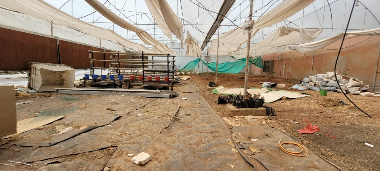
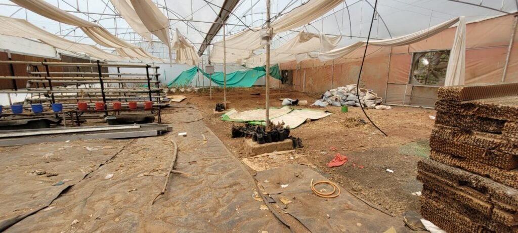
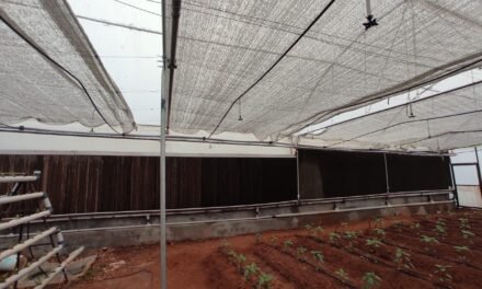
I have visited the poly-house and seen the condition of the poly-house and taken reading inside at almost every sections. The reading were taken at points like along the centre of the poly-house, left side axis along fan pad, between the two fan at equal distance, right side axis along the fan pad.
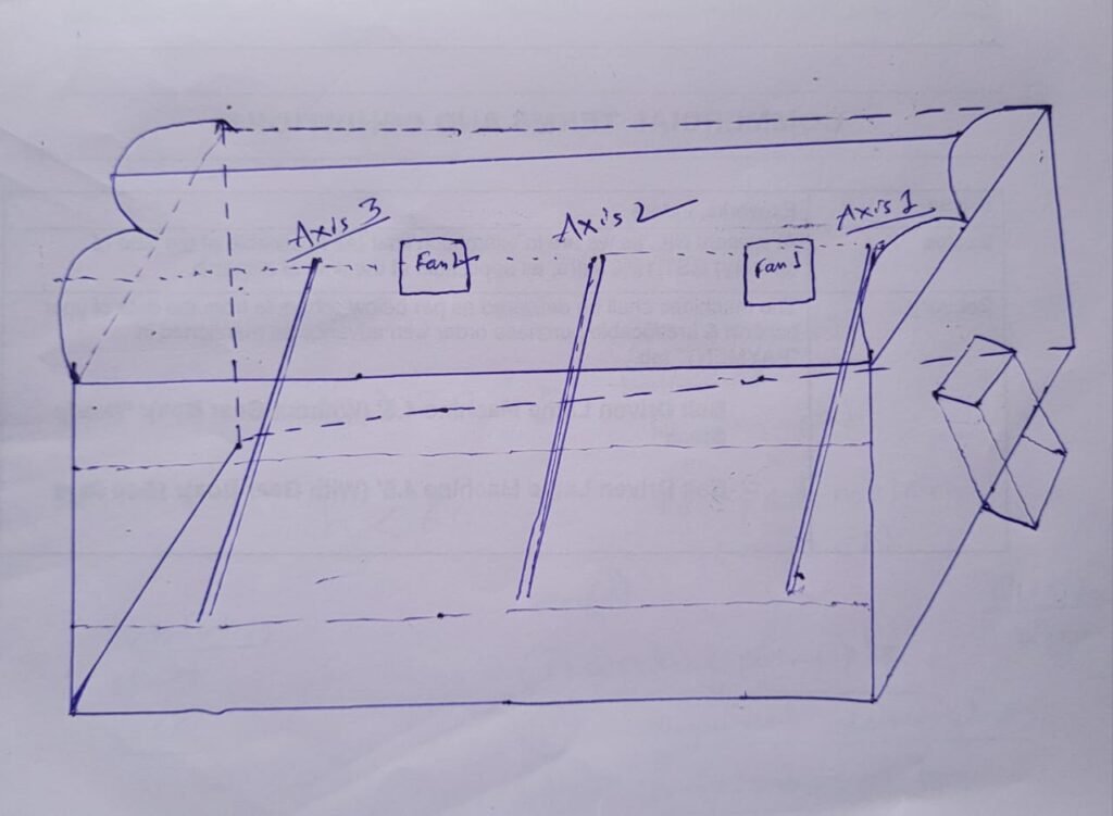
Temperature observation inside polyhouse at different 4 axis –
https://1drv.ms/x/s!AhypCsFYbnwdhEVL63hqZNrOfmVu?e=1Jl8Kq
From the above data I have understood that at the left side of the fan nearer to the enterance of the polyhouse there makes move heating inside polyhouse.
At the axis 1 the temperature inside polyhouse remain high than any other axis inside polyhouse.
The axis 1 – is in axis of fan-pad system.
I have taken the reading inside polyhouse at 1 m above the ground level as because from the ground to max 1.5 m height any crop can grow inside.
Temperature reading was taken with the help of Thermometer in the different time on that day.
Discussion done with Ranjeet sir for the installation of pad in the polyhouse.
Temperature was taken in the three major points inside the polyhouse so that we can see the temperature and we can work on the automation of the machine inside the polyhouse to control the temperature and humidity .
The links are provided for study on temperature inside the polyhouse at three consecutive points and at different time and the temperature were taken at two different heights first at 0.85 m and another at 2.5 m height from the ground.
This 3 links are given to see the temperature inside the polyhouse .
1- The temperature was recorded at the 1m right side of the fan (inner side or opposite side of the enterance) of the polyhouse at the axis the fan- pads.
2- the temperature was recorded at the midway of the polyhouse between two fans at the axis of the fan- pads.
3- the temperature was recorded at the 1 m left side of the fan (nearer to the enterance) at the axis of the fan-pad .
I met with Ranjeet sir, he told about the arrival of all the required equipments and materials for installation of polyhouse and told me to work on installation.
I listed all the arrived materials need to set up or installation.
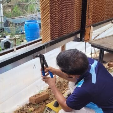
installation of polyhouse starts from day 06/06 with some helping hands
As some of the pads were left for installation so we start work on it for setting it up.During setting up many problems arrived like before setting the pads we have to fix the gutter line below the pad so that the overflow of the water received by the gutter pipe for reuse of the water So start to fix the gutter pipes
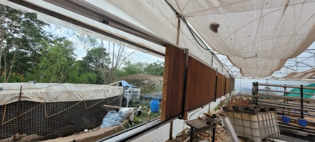
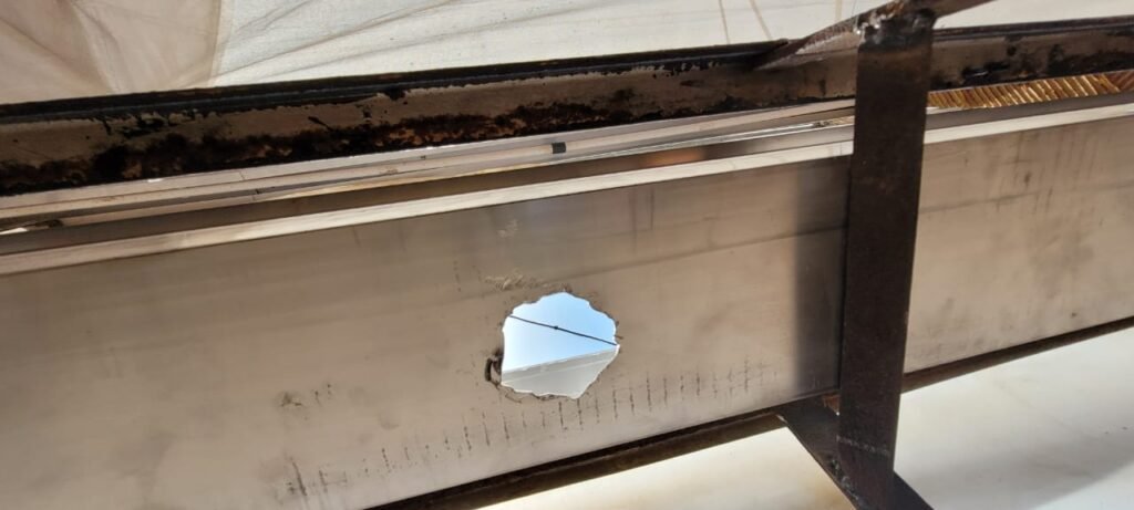
For installation of the pad many works have been done ,like Drilling, Welding, Cutting of metal with help of hand Grinder, Rivetting etc.

Discussion with Arun Dixit sir and Prasad Sir with all interns on Incinerotar . The design and placement of burners in the Incinerotar was discussed and found a solution for its better working.
We have started the work of the pipe line section for collecting and distribution of water to the pads.
12/06/2023
Plumbing work inside the polyhouse for supplying water into the pads and receiving water from the pads.
All the gutter holes has been done for collecting the extra water which were led by the pads after soaking into it. At first all water receiving gutter pipes were installed accordingly. Then all the pads were placed on it and then supply pipe were installed on the pads.
Plumbing done outside the polyhouse for water supply to the tank from main water stored area .
Side of the polyhouse the it was installed.
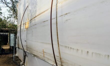
For supplying water into the pads water tank was taken at the back side of the polyhouse. I have taken 4 water tanks and all are interconnected to each other . So that water level in all the tanks are kept in same level and there were no problem in supply of water into the pads . Water tanks were kept in same level to each other and lower to the polyhouse as because the collected water comes back into the tank .
A 1 hP pump has been taken for supplying of water into the pads. And all the 4 tanks were taken and interconnected with pipes. Water was filled into the tanks .
When the pump was started to supply water into the pads it was observed that the capacity of the pump is too low to supply water to the whole pads in the polyhouse. The pump capacity was 0.653 Lt/sec.
For adequate supply of water into the pads we have choosen a 2hP pump. For placement of the pump there some problem was appeared like the previous connection of the pump cannot be applied to the 2 hP pump . Plumbing done for the placing the 2 hP pump.
All the plumbing work for placing the 2 hP pump was made and water tanks were filled with water.
As there was some impurities in the water tank so that the tanks water was distributed inside the polyhouse on the soil . And then all the four tanks was cleaned . As because there inside the water of the water tank there should not any growth of algae for that it was cleaned and left to dry.
Water filled in the four tanks and the pump was started to supply water into the pads . It was good to see that the 2 hP pump was good for supplying water into the pads but after applying water into the pads some leakage were found in the pipes .
so that at first all the leakage were identified.
Black thick polyethylene was taken for covering the water tanks . Polyethylene was applied for covering the tanks and it was covered.
Pump was started and for identifying of the leakage in the pipes was given into the pads.
I have found many leakages in the pipes and some overflow of water from the pads were observed after applying water into the pads by the 2hP pump. we found all the leakage and filled the leakage with silicon glue and solution on the gutter pipe and supply pipe and receiver pipe .
The flow rate of the 2hP sewage submersible pump is 3.5 L/sec .
It takes about 5 min to fully wet the pads .
specifications
Type- F25US Volts- 220 V,50 HZ
kW/HP- 0.75/1 Current- 6.0A
CAP- 27mF,440V Speed-2800 rpm
Head-7m Head Range-4/8m
Discharge rate- 12600 lph Max Discharge -24500 lph
Delivery size- 50mm
The motor takes 5 min to wet all the pads but 3percent of the pads remain dry after wetting al the pads and the collector pipe starts to supply water into the main tank after 1m of interval of starting the pump.
After Installing all fan-pad system I have taken reading readings of temperature and humidity inside polyhouse at day time. Once I have taken before applying water on the pad and another after applying or wetting the pads.
After taking readings once in keeping dry to the pads and once after applying water into the pads, I came to know there is a drastic change in Humidity,i.e,the humidity level increases and the temperature in the Poly-house only increases by 2-3°C.
Some calculations are done on heat requirement in poly-house, water required in poly-house to remove the heat , how much heat to be removed out through the fans to decrease the inside temperature and how much time the fans to be kept ON so that the inside trapped heat moves out and the poly-house become cool.
A. Calculating CO2 requirement Vs Exhaust fan run time of polyhouse:
This calculation is based on CO2 requirement for the plant, hance the amount of air which should enter in polyhouse and should leave poly-house so that the concentration of CO2 in the poly-house remains more or less at 420 ppm which is more or less as good as the outside temperature of the poly-house. Our polyhouse has 500 m2 of area where we are going to plant capsicum.
In a 500 m2 land 1875 of capsicum plant can be grown.
1 plant will produce about 5.5 kg biomass (2 kg plants + 3.5 kg fruits) in its total growth in 9 months, then 1875 plants will produce 10312 kg total biomass in their total life span (wet biomass).
5.7 kg of dry biomass per plant
Now biomass content cellulose ,lignin and very small amount of glucose.
So looking at the carbon : oxygen in cellulose and hemicellulose, we came to a calculation that every C6 unit will have a molecular weight of 153 and the amount of CO2 is 6*44= 264 gm
264 gm CO2 – 153 gm of biomass
Then 5.7 gm of biomass – 9.83 gm of co2.
Now, 9.83 kg of CO2 per day will be required by 1875 plants
Let assume the efficiency air entering into the stomata and exhaled out through stomata is 25%
i.e, 9.83/0.2 = 49 kg CO2 will be required by 1875 plants ( as human being inhales O2 around 21% and exhale CO2 i.e 4.1% of O2 is used in every breath of human being which is about 20% efficiency of human lungs).
1 lit air – 0.000516 gm CO2
so, 49 kg CO2 will need 94961240.3 lit of air = 94961.24 m3
This is equal to 122499.7 Kg of air.
Now coming to the calculation of Time required to displace the 94961.24 m3 air out of the poly-house through the fans which is having 500 m3/min displacement of air outside of the poly-house, as we have 2 such fans, so the displacement of air is 1000 m3/min .
Then, 94961.24/1000 = 94.96 min
= approx. 1.5 hrs/day
Approx 1.5 Hrs fan ON time for getting sufficient CO2 inside polyhouse
- Temperature and Humidity controls inside poly-house
Water required for humidity rise inside polyhouse:
If we consider 40o C and 15 % RH outside polyhouse and we wish to maintain 30 o C with 60 % RH inside polyhouse
then, according to the psychometric chart we received the data
Specific humidity for 40 C & 15 % RH – 9.00 gm/kg
Specific humidity for 30 C & 60 % RH – 20.5 gm/ kg.
So, 20.5 – 9.00 = 11.5 gm water / kg air required to be evaporated
If 123900 kg of air is required for sufficient CO2 in a polyhouse.
122499.7 * 11.5 g = 1408.75 kg (lit) of water will be required for cooling the polyhouse.
1408750 gm water *2400 j/gm = 3381000 kJ heat will remove from polyhouse
Heat required for temperature reduction requirement:
- Temperature reduction:
M*cp(ΔT) = 122499.7* 1 * 10 = 1224997 Kilo joules
M- volume of air
Cp – specific heat of water ΔT 40 C – 30 C = 10 C
b) Heat required for water evaporation :
for evaporation of 1408.75 kg of water the heat needed is 1408.75 kg water *2260 KJ/kg
= 3183775 KJ
c) Heat trapped inside polyhouse:
As 451 m2 is the surface area of the polyhouse
So 451(surface area of polyhouse) * 25 mJ = 25*106 J *451
25*106 *451* 5 % (will get trapped) = 451*1250 KJ
= 563750 KJ will be trapped inside polyhouse
Total energy required a-b+c
= 1224997-3183775+563750 = -1395028 KJ
No extra water necessary for cooling but temperature of poly house will drop below 30o C.
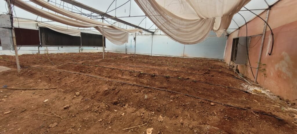
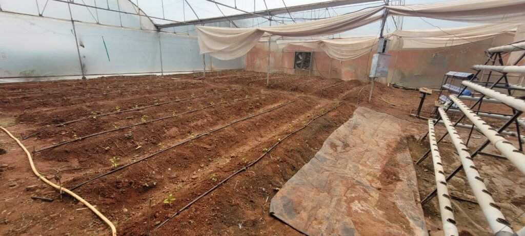
In the poly-house soil preparation was made and then beds formation was prepared for plantation of plants and vegetables.
After that on that beds water has been given to make the soil good for growth of plants. Then for plantation drip irrigation system is installed for supplying water in the roots of the plants and vegetables, for drip irrigation system I have used a 32 inch diameter main pipe to supply water from tank, and supply pipes are attached with the main pipe , the diameter of the supply pipes are 16mm.
I heve taken Capsicum to plant inside the poly house .
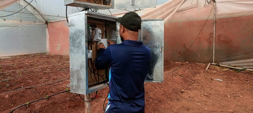
Centralized Electrical Connections –
All the connections in the polyhouse been centralized to a point in the polyhouse. The switch of the foggers pump, pads wetting water supplying pump, MCB of the fans, switch of the motor for hydroponics , this all connections are brought together in the center of the polyhouse so that we can control it easily without any trouble.
AUTOMATION
At first for automating the fans I have taken a automatic cyclic timer which operates manually and automatically both methods.
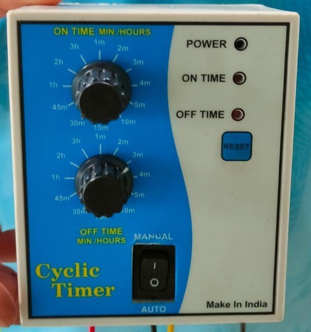
In this cyclic timer there was some problem and was inaccurate for automation. In this timer there was two regulators one was for running machine time and another was for keeping it off for a certain time intervals.
When I fix it with the fans at that time it is not known to me that it was running in 3 phase current ,so it can’t take the load and capacitors inside the timer was burnt. So that the Timer was disconnected from the fans. And also it was not been operated by a mobile or any other device and many drawbacks were seen in this Cyclic timer device.
in place of Cyclic timer I have taken Arduino for automating the polyhouse fan-pad system.
Arduino is a device that is operated by setting command on it to run any device through it.
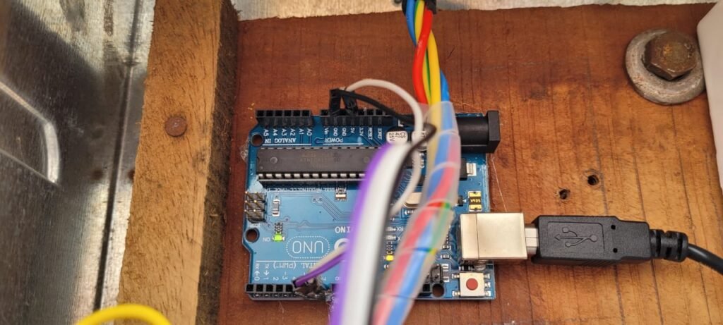
As per the requirement of the fan-pad system we can operate the fans . How much time to be the fan should be on in the polyhouse it will be commanded in the Arduino and it can be operated easily in according to any other devices.
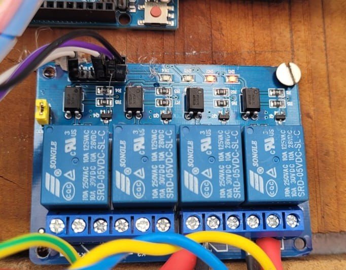
RELAY is an electrically operated switch. It consists of a set of input terminals for a single or multiple control signals, and a set of operating contact terminals.A relay module is a relay that’s been mounted on a board with other components to provide isolation and protection. This makes them easier to use in a variety of applications. The use of relay module devices offers a simple and convenient way to control electrical equipment systems remotely. It is connected with the Arduino and Arduino is connected to the fans ,here this build a circuit combination and in this way this is operated.
uses of a relay module in various places are
1 Used in over voltage/under voltage protection system.
- Mains Switching.
- Speed control of motors through start-delta converters.
- Automatic electrical appliances.
- Electrical isolation in between high & low power sources.
- Lights.
Using relay I have connected it with main connection of current supply from current generating from Solar panels , the Relay works to switch ON and OFF to the fans.

As per the block diagram of the Automation Circuit –
AHT25 – The AHT25 temperature and humidity sensor is equipped with a newly designed ASIC dedicated chip, an improved MEMS semiconductor capacitive humidity sensor element and a standard temperature sensor element, and its performance has reached the industry’s advanced level. The improved new generation temperature and humidity sensor AHT25 has more stable performance in harsh environments and can maintain good accuracy in a larger measurement range.
The AHT25 can be widely used in consumer electronics, medical, automotive, industrial, meteorological and other fields, such as: HVAC, dehumidifiers and refrigerators and other home appliances, testing and testing equipment and other related temperature and humidity testing and control products.
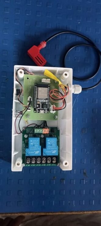
AHT25 senses the Temperature and Humidity inside the Poly-house and sends the data to ThingSpeak Cloud and ESP 32 is the wi-fi bluetooth connectivity sensor which connects AHT25 and ThingSpeak Cloud to send the data into cloud. For ESP 32 the power supply to the circuit is 5V and 1A.
AHT 25 is also connected to Relay Module (50 A ,5 V) for sending data accordingly to it which receives the data collect the command and works as per the command. Here two relay modules are there one for giving signals to Fan-Pad motor and another for giving signal to Fogger motor.
Conditions for operating the Fan-pad motor and Fogger motor by Relay module are:
t > 30°C (Fogger motor will get started for 2 min)
h < 60% (Fan – pad motor will get started for 10 min)
https://thingspeak.com/channels/1093286
This is the link of the ThingSpeak Cloud to see the data stored from the poly-house during the whole day time and it will represent its accordingly by graphical representation , there will always two graphs one of Temperature vs Time and another one of Humidity vs Time.
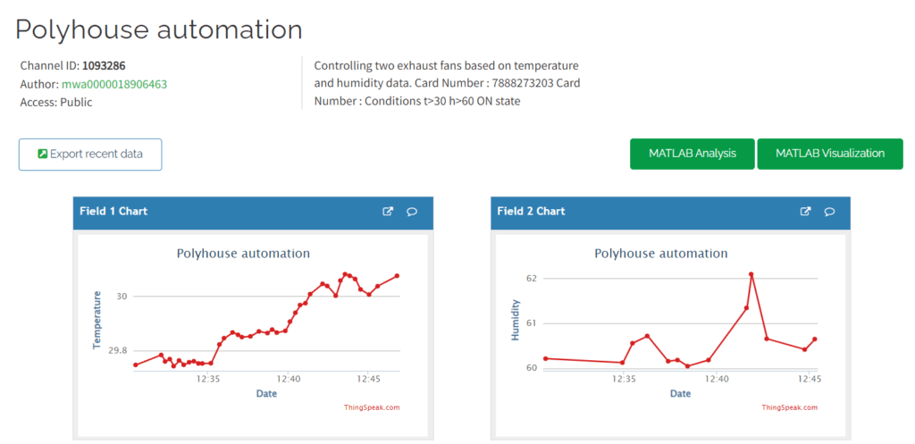
The code that was applied for operating the Fan-pad motor and Fogger motor under the conditions applied –
Conclusion
It is more easier and more efficient as compared to on field farming .
It can be operated from any where.
