Assignment – 1 Water level sensor with 1 relay channel module
Problem :
The need of this project is to avoid wastage of water. Because sometimes people forget to switch off the motor when the tank is full, due to which water is wasted. To avoid this problem this project came up. By using this water level indicator system we can monitor water level and water consumption.
Purpose:
The water level indicator along with monitoring will be developed keeping in view the following objectives:
Component:-
Single Channel Relay Module
float sensor
speaker (12v)
SMPS (12v 2amp
Single Channel Relay Module
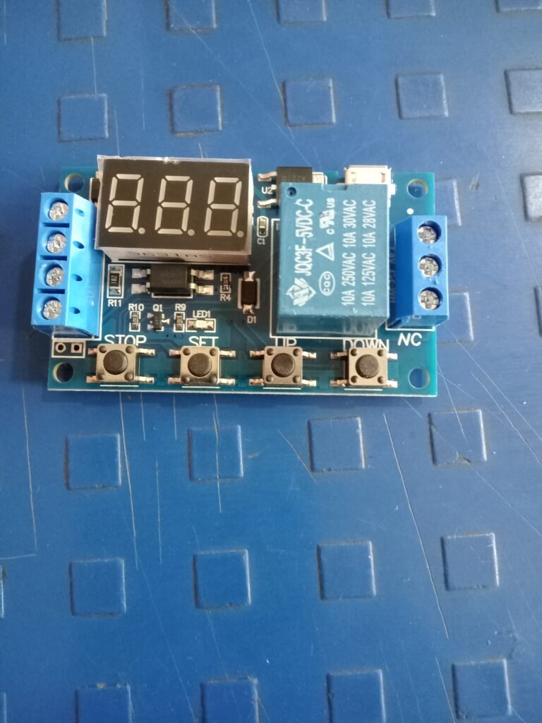
This is a 6-30V 1-Channel Delay Power Relay Module with Switch for Digital LED Display. It is mostly used in home automation delay timer control switch module timer controller. The module operates on an operating voltage range of 6-30V, it also supports Micro USB 5.0V power supply. Output Capacity: Can control the device within DC 30V 5A or AC 220V 5A. It can be applied in many fields
Set Time:
First, make sure the relay operation mode
According to the operating relay mode, the main interface (the power module will flash the current operating mode; standard mode P1.1, then come to the main interface); Long press the SET key two seconds and then select and enter the selection interface mode; Pressing UP, DOWN key to select mode setting (P1.1~P4)
After selecting the mode, short press SET to set the corresponding parameter, then the parameter you want to set will flash (OP power on time; CL power off time; LOP is cycle time, infinite cycle); By UP, support long press (quickly increase or decrease) and short press (increase or decrease by 1 unit), to set the DOWN parameter value; Press the STOP key to select the decimal place after setting the parameter value; choose the time interval (the corresponding time interval is 0.1 s-999 min); Short press SET to set the current mode next parameter, the process is the same as above
After the setting mode parameter, press and hold the SET button then flash the current configuration mode, then return to the main interface; Define success parameters Main interface: When the relay does not work, it will show 000 (no decimal point); Operating state relay, screen has decimal point
Float switch
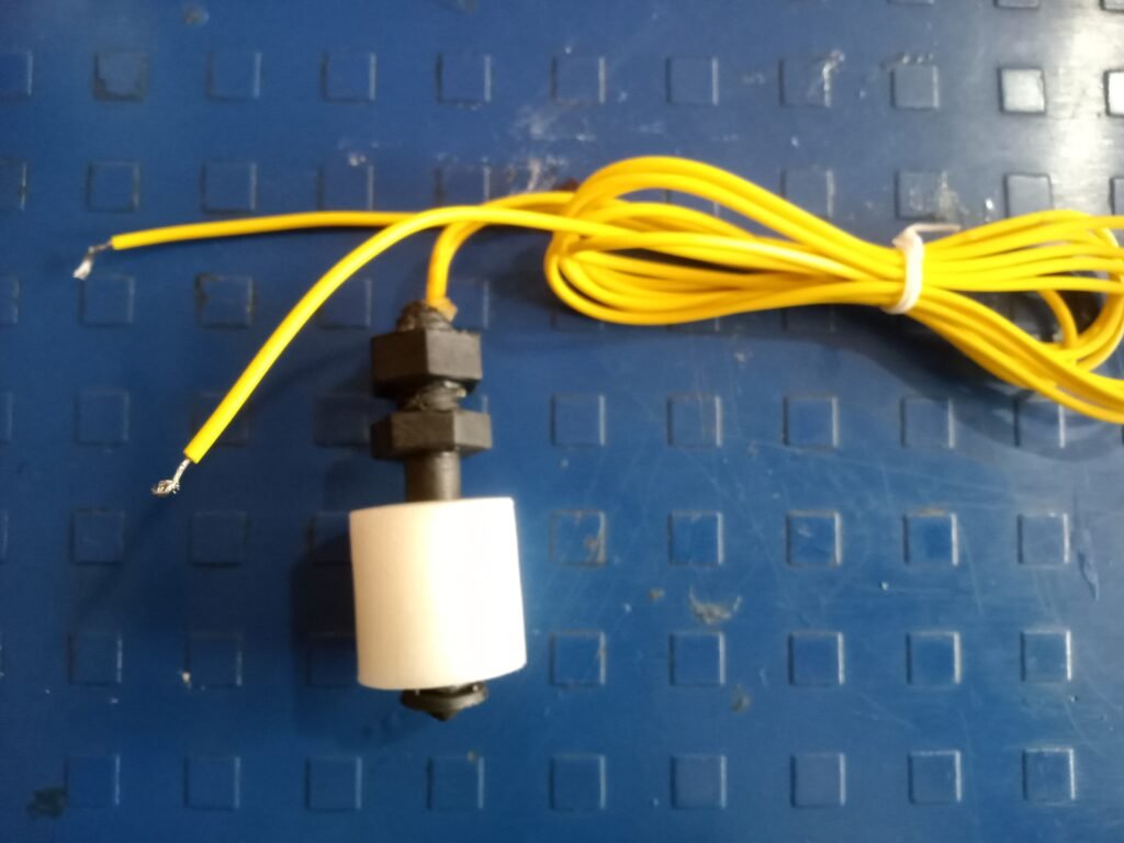

A float switch is a device used to sense the level of liquid within a tank. The switch operates a pump, an indicator, an alarm or other device. Use them with hydroponics, saltwater tanks, freshwater tanks, gardening, fish tanks, pumps, ponds, basement alarms, boats, cleaning machines. Reverse the float to switch it from normally open to normally closed Can be easily converted to.
12V 2A SMPS -DC Metal Power Supply –

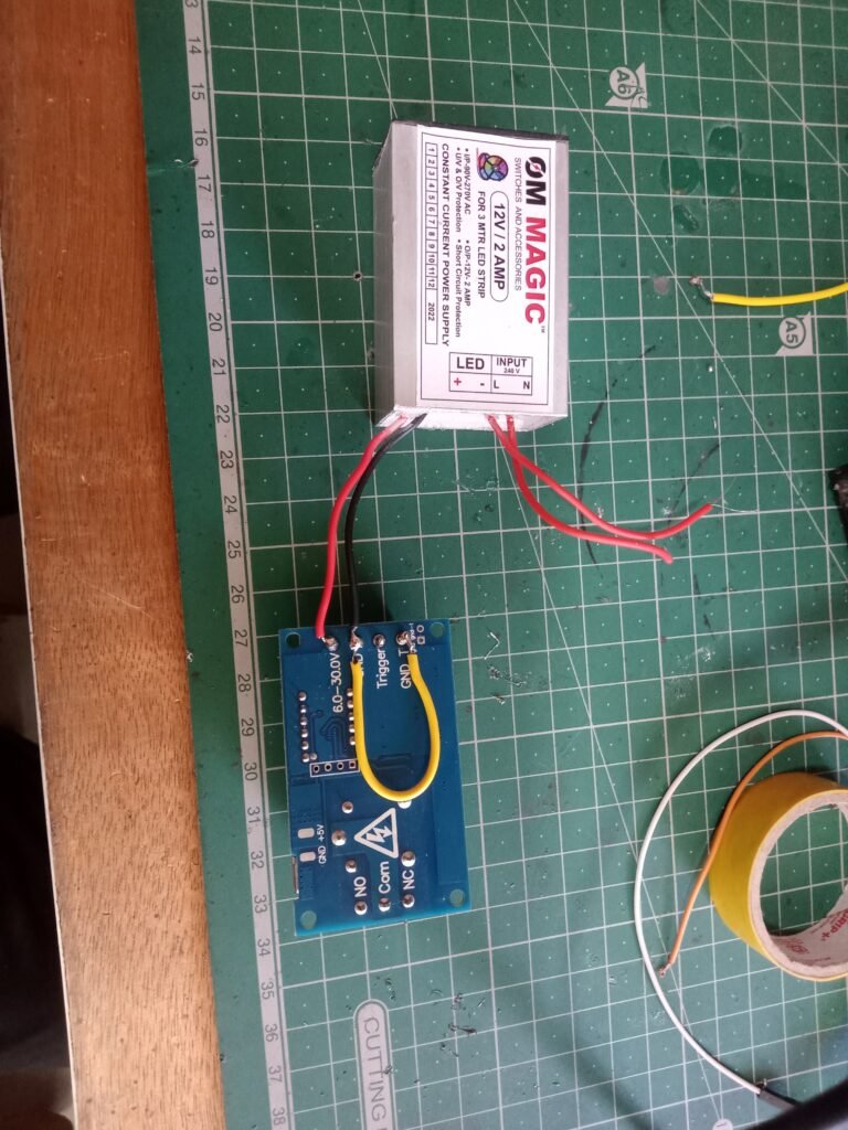
Specifications:
Input Voltage: AC 100 – 240v 50 / 60Hz
Output voltage: 12V DC, 2A
Protection: Overload / Over voltage / Short circuit
Auto-recovery after protection, Universal AC input / full range, High quality and high performance, No minimum load. ,Compact size light weight. ,high efficiency, reliability and low energy consumption.
Category – Switch Mode Power Adapter (SMPS)
Output Type – DC
Output – 12 Volt 2 Ampere
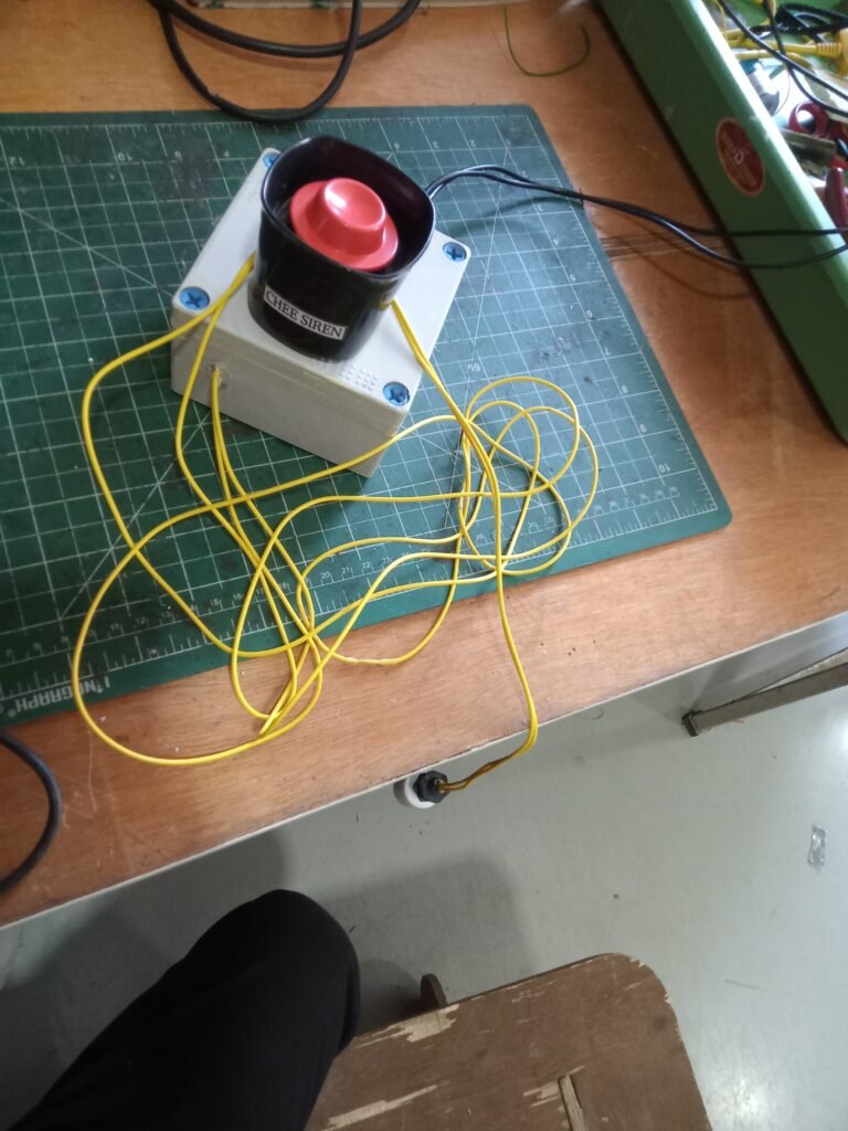
Siren :-
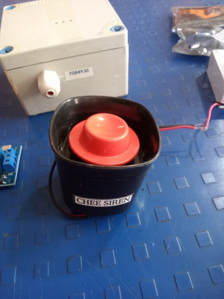
DC 12V Mini Horn Siren Home Security Sound Alarm System Anti-theft Speaker Buzzer. This product is used with a system to respond to signals from the alarm keypad/console.
Component Cost :
| Components | Price |
| 6-30V 1-Channel Power Relay Module | 289/- |
| 12V 2A SMPS | 245 |
| Water Level Sensor Float Switch | 105 |
| DC 12V Wired Mini Horn Siren | 259 |
| Total Price | 898 |
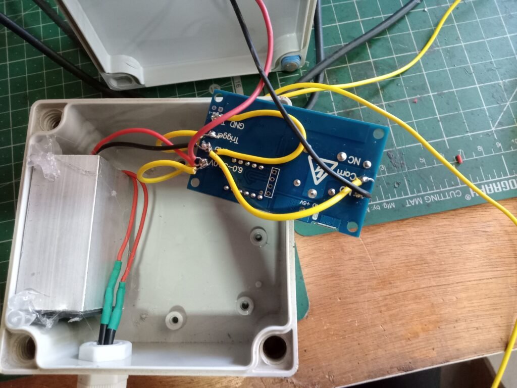
circuit diagram :

Prototype Video

Assignment – 2 Arduino uno with Water level indicator for VA Dic boys Hostel
Introduction
Overhead tank overflow in homes is causing unnecessary wastage of water. Water level indicators can provide a solution to this problem. The main components used in this device are the Arduino Uno microcontroller, the sensor, and the horn. By using this project we will be able to control wastage of water and manage water level in various systems like water tank, boiler and swimming pool etc..
Problem statement :-
Once the water tank is full, some water is wasted.
purpose:
Water should not be wasted.
time saving
power saving.
Component:-
Arduino Uno
float sensor
speaker (12v)
SMPS (12V 14A)
relay (5v)
Float sensor
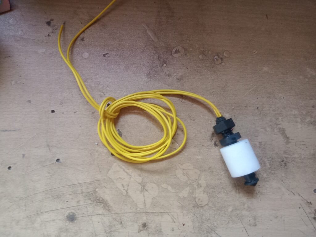
A float switch is a device used to sense the level of liquid within a tank, it may actuate a pump, an indicator, an alarm or other device.
A float switch is a device used to sense the level of liquid within a tank. The switch may actuate a pump, an indicator, an alarm or other device. Hydroponics, Saltwater Tanks, Freshwater Tanks, Gardening, Aquariums for Power Head Control, Pet Bowls, Fish Tanks, Filtration, Heating, Pumps, Ponds, Basement Alarms, Boats, Air Condition Drain Pans, Pressure Washers, Use them with the carpet cleaning machine. In reef aquariums, fluid controls, ice machines, coffee pots, marine, automotive, automobiles, tropical fish tanks, evaporator coils, condensation lines, relays, or whatever your project may be. It can easily be converted from normally open to normally closed by reversing the float.
Arduino UNO
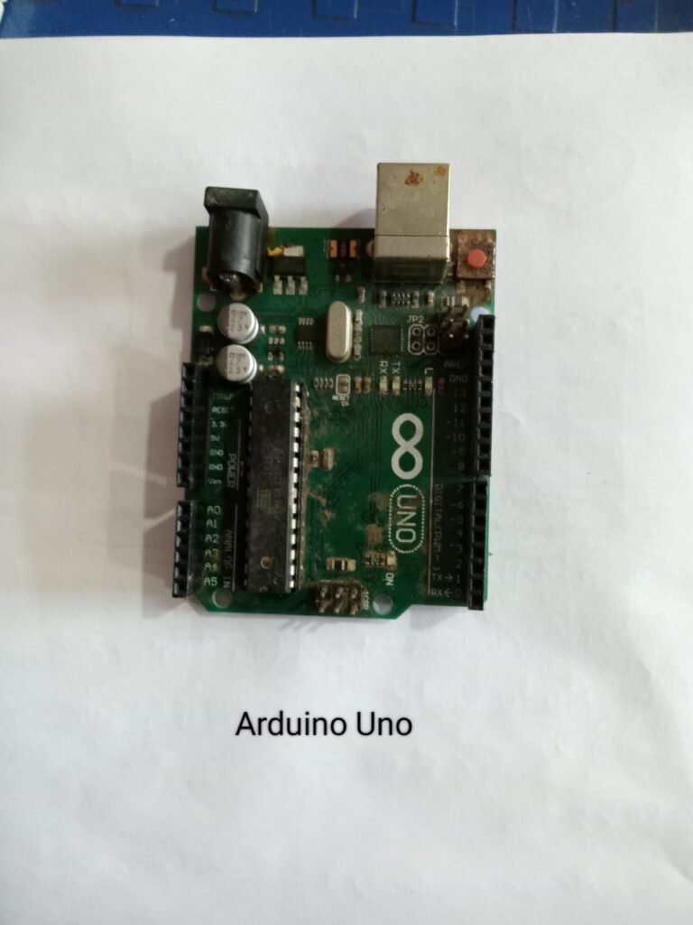
Arduino UNO is based on an ATmega328P microcontroller. It is easy to use as compared to other boards, such as Arduino Mega Board, etc. The board contains digital and analog input/output pins (I/O), shields, and other circuits.
Arduino UNO
Power LED Indicator – The status of the LED shows that the power is active. When the power is off, the LED will not light up.
Digital I/O Pin – The value of a digital pin is HIGH or LOW. Pins numbered D0 to D13 are digital pins.
TX and RX LED’s – Successful flow of data is represented by the lighting of these LEDs.
Reset Button – This is used to add a reset button to the connection.
USB – This allows the board to be connected to a computer. This is essential for programming the Arduino UNO board.
Voltage Regulator – The voltage regulator converts the input voltage to 5V.
GND – Ground pin. The ground pin acts as the pin with zero voltage.
Vin – This is the input voltage.
Analog Pins – The pins numbered from A0 to A5 are the analog pins. The function of the analog pin is to read the analog sensor used in the connection. It can also act as a GPIO (General Purpose Input Output) pin.
Relay
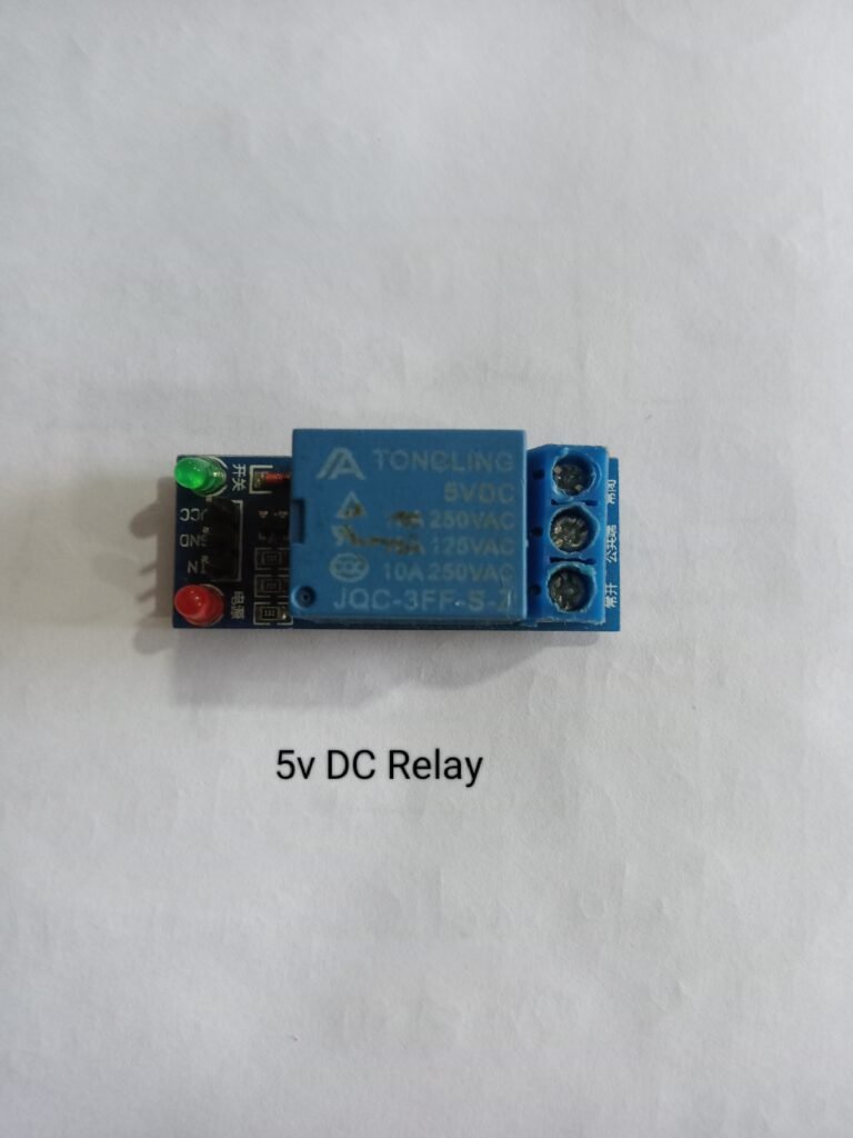
1 Channel 5V Relay Board Module for Arduino PIC AVR DSP ARM. A wide range of microcontrollers like Arduino, AVR, PIC, ARM etc can control it.
Each requires 15mA – 20mA driver current and is equipped with a high current relay: DC 5V / 10A, AC 250V / 10A
SMPS:-

Power supply circuit plays a vital role in every electrical and electronic circuit from owl circuit to supply power to computer and various machines. The full name of SMPS is Switch-Mode Power Supply. SMPS is defined in simple language when the power requirement comes in the form of a switch. In which electrical energy is converted from one form to another with essential properties called SMPS.
ac to dc converter smps
In this type of SMPS, the input supply is AC and in the output we get DC supply. Rectifiers and filters are used to convert this AC power to DC. This uncontrollable DC voltage is fed to the affected power factor correction circuit. This is because there is a low current pulse inside the rectifier around the peak of the voltage.
Speaker (12V) :-
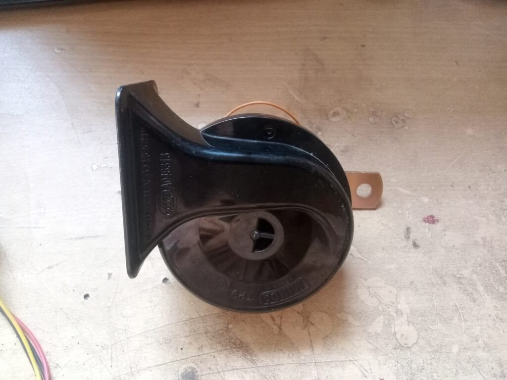
12v 3ah speaker is used for this project. The reason for installing this speaker is that when the water tank is full, its loud sound can be heard by everyone.
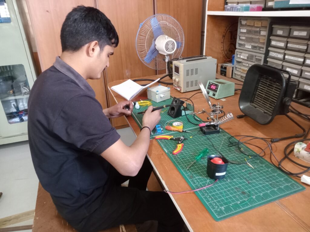
first its diagram came out
Find the components that fit inside it and
read about them and
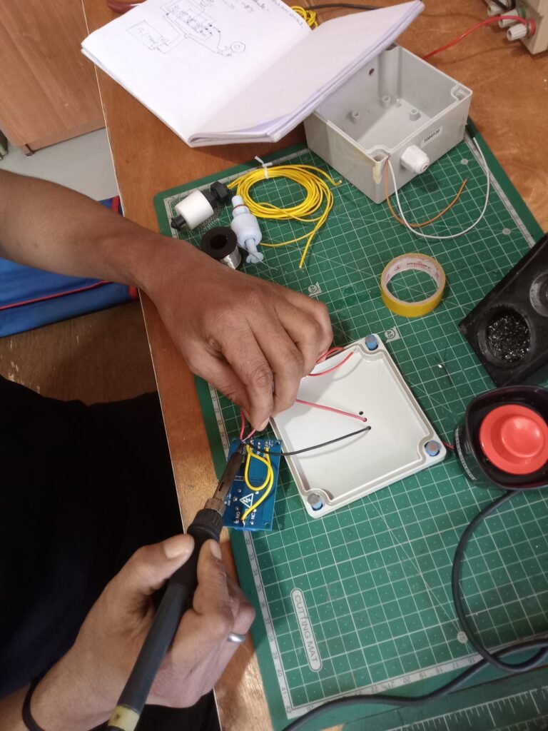
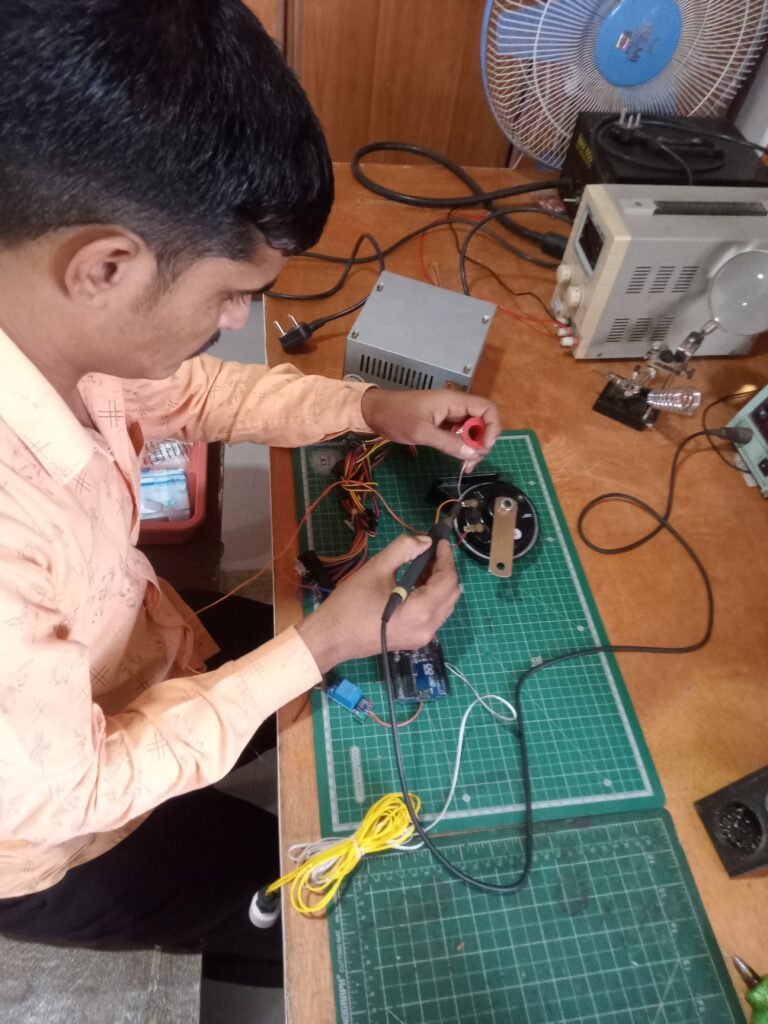
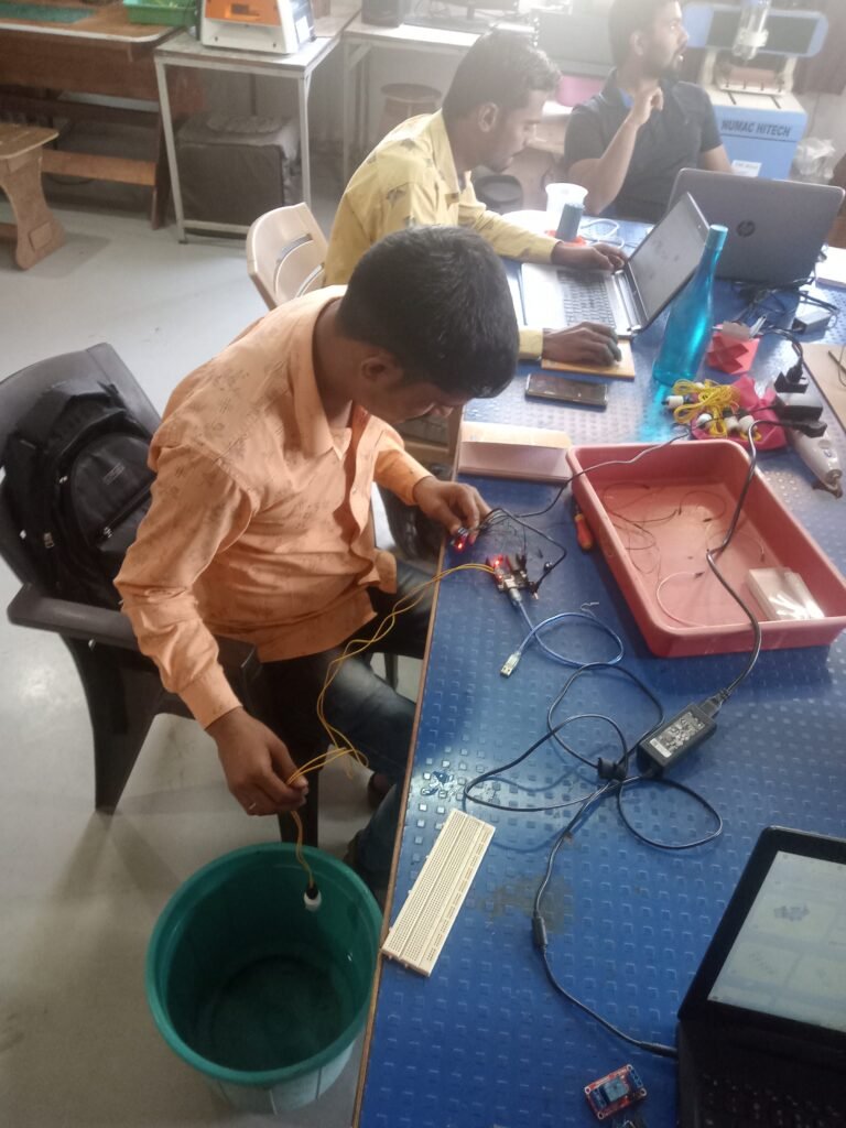
Soldering electronic components and

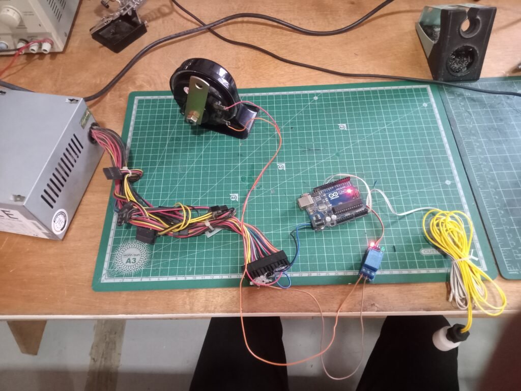
Circuit diagram :-

connection pin
| Arduino | connecting pins |
| 5v | relay pin 5v |
| Gnd | Relay Pin Gnd |
| pin9 | relay signal pin |
| pin 11 | float sensor (+) |
| Gnd | float sensor (-) |
| relay com pin | speaker |
| Relay NC Pin | SMPS (-) |
| SMPS(+) | speaker |
Connect each component as shown in the picture and upload the code to Arduino.
Upload the code to Arduino.
#define relay 9
#define FS 11
int senstate;
bool x;
void setup() {
Serial.begin(9600);
// initialize digital pin 8 as an output.
pinMode(relay, OUTPUT);
pinMode(FS, INPUT_PULLUP);
digitalWrite(relay, HIGH);
x=false;
}
void loop() {
senstate = digitalRead(FS);
if (senstate == 1)
{
if (x)
{
digitalWrite(relay, HIGH);
delay(500);
digitalWrite(relay, LOW);
delay(1000);
digitalWrite(relay, HIGH);
delay(500);
digitalWrite(relay, LOW);
delay(500);
digitalWrite(relay, HIGH);
delay(500);
digitalWrite(relay, LOW);
delay(500);
digitalWrite(relay, HIGH);
delay(500);
digitalWrite(relay, LOW);
delay(500);
digitalWrite(relay, HIGH);
x = false;
Serial.println(“STEP ONE DONE”);
}
}
else if (senstate == 0)
{
if (!x)
{
digitalWrite(relay, HIGH);
x = true;
Serial.println(“STEP TWO DONE”);
}
}
delay(1000);
}
then tested and
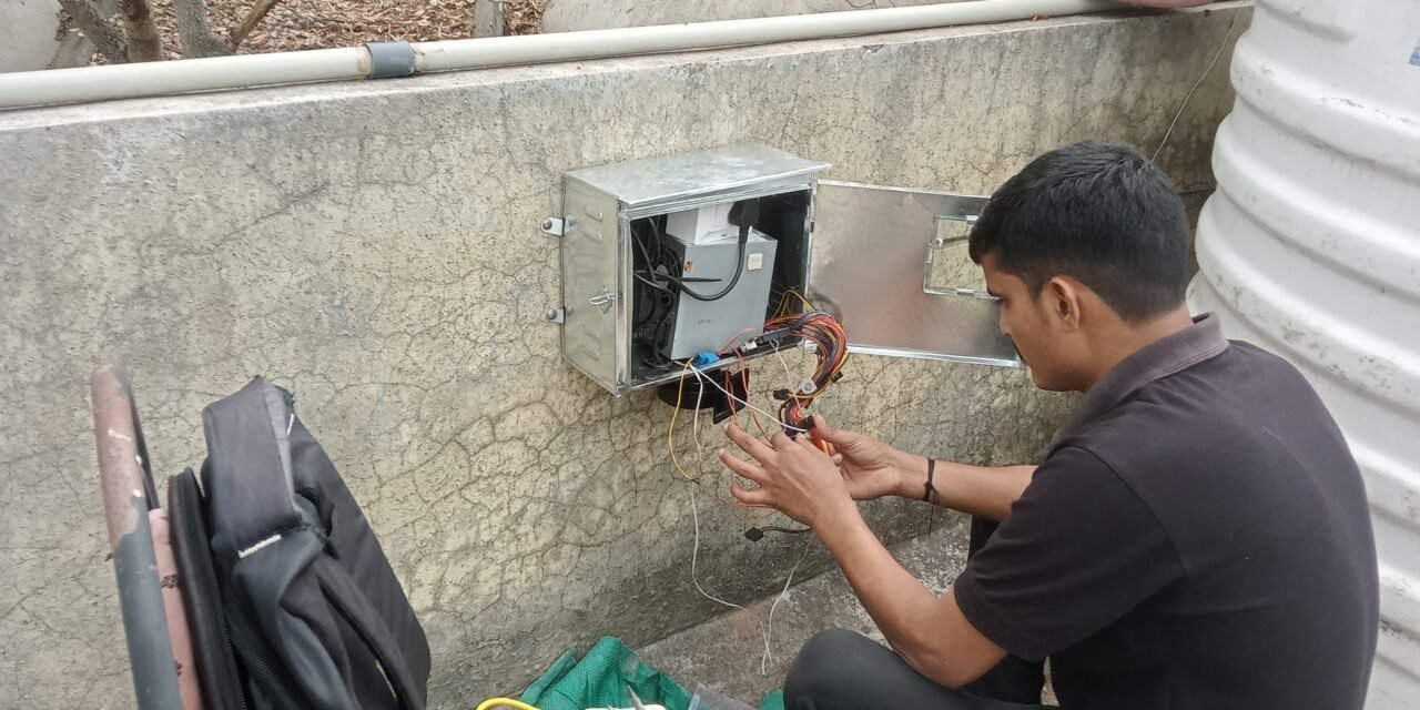
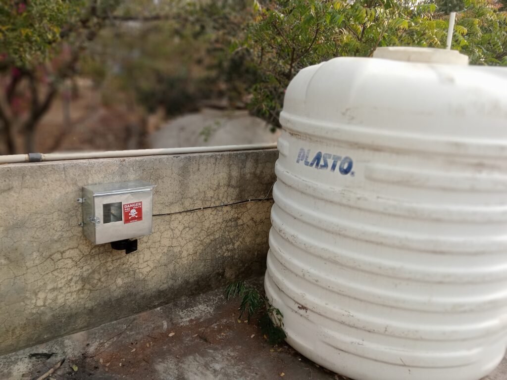
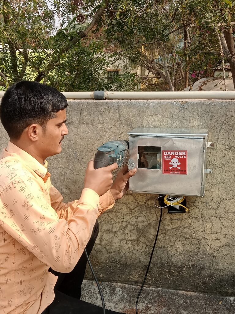
Location selected for installation
To install the safety box, the box was drilled in the wall and then the electric switch and socket were installed and
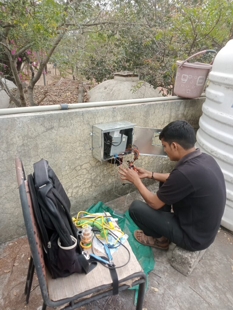
then checked by running
After installing this, trouble shooting was happening, so that too was checked and rectified.
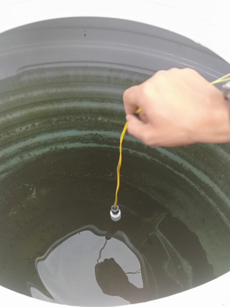
Making the cover for the control unit uses the junction box and installs the setup. Swim deep in the water tank.


There were some problems building this project
loose connection
code error
proper dc adapter
conclusion
First of all understood the problem, then its diagram came out, found the components used inside it and read the information about them and took out the cost analysis, then purchased from the market and soldering the electronic components and then testing was done and after applying it, troublesuiting was happening then that too was checked and fixed
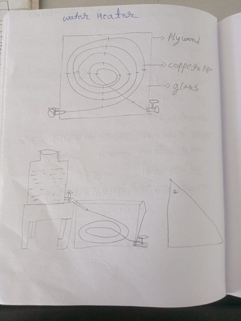
Thermo dynamic solar system for water heating
Thermo dynamic
Food lab
Water is needed to make tea, it has to be heated in a water heater, so first we have to do thermodynamics, the problem is that the water needs to be heated to make tea.
Tea
Sugar = 450g
water = 1lt
Milk = 4lt
Tea leaves=80g
Temperature when sugar was added in the middle =70°c
Temperature at which the tea is fully brewed = 90°c
Whole tea leaves after making tea = 350g
Complete tea made = 5lt
In discussion with Prasad Sir Dixit Sir Swarna regarding the food prepared in the kitchen, the idea of making heater plate fitting tua on solar energy instead of gas, the fuel by which food is cooked in the students’ kitchen, which is gas. To convert it into solar energy for making plates, first of all we have to do thermo dynamic of the gas burning in the kitchen.
08/12/2022
Dry flour =7.730g
Wet flour =10.306g
water =4.5lt
Temperature on stove=90°c
Gas before cooking=30kg
Gas after making 78 chapattis = 27kg
09/12/2022
food lab
Sugar = 450g
water = 1lt
Milk = 3lt
Tea leaves=80g
When sugar is added in the middle then the temperature = 70°c
Temperature at which the tea is fully brewed = 90°c
Whole tea made Tea leaves found after making tea = 360g
Tea Bunny=4.175g

kitchen
Dry flour=8.130g
water =4.5lt
Dry flour put=2.426g
Wet flour=10.755g
wet dough left =1.676g
Dry flour left=0.500g
Weight of chapati =0.106g
Weight of whole chapattis=7.930g
Chapati made = 79
13/12/2022
food lab
Milk =3lt /2.970g
Water1lt /0.990g
Sugar = 450g
Dry tea leaves=80g
Tea Bunny=4.175g
Tea leaves found after making tea = 360g
medium temperature =70°c
Temperature when tea is ready = 90°c

15/12/2022
water=1lt =0.990g
Milk=3lt =3.078g
Dry tea leaves=0.70g
Sugar=450g
Weight of gas before making tea=20.488g
Tea made=3.700lt =3.970g
Tea leaves found after making tea = 306g
Weight of gas after making tea=20.429g
medium temperature=70°C
Completion temperature=90°C
Input=0.990+3.078+0.70+0.450=4588g
water + milk +tea leaves +sugar
Output =3.970+306=4276g
tea + wet tea leaves
Different=312g
Gas =20.488–20.429=59g
Different=59g
Intial temp=25°c
Final temp=90°c
Different=90–25=65°c
=4588*1*65Cal (sensible heat)
=298220Cal =298.22kcal
Latent heat
= 540*312=168,480cal
=168.48kcal
1000kg=55000kj=12257kcal
59g =723.2kcal
Input energy=723.2kcal
Used energy=466.7kcal
%Efficiency= output*100
Input
=466.7÷723.2*100=64.53%
Temperature start=25°c
End=75°c
Different =50°c
Input*different temp
4588*50=239400
to do in kcal (1000)
239.4Kcal
Temperature taken to heat the tea = 239.4kcal
Conclusion
If we heat 1 liter of water per day on gas, then by solar water heater we can save Rs.56 in a month.


