Date – 10/11/2022 to 27/12/2022
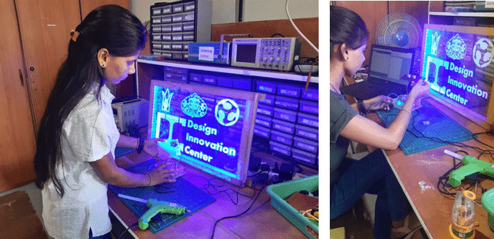
Yogesh Kulkarni sir gave me the project to make DIC board.
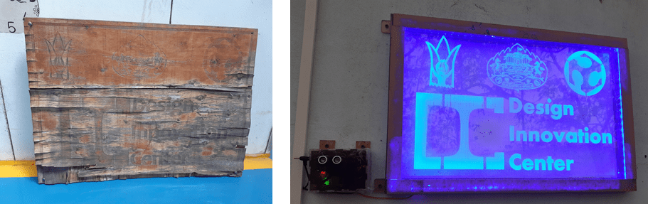
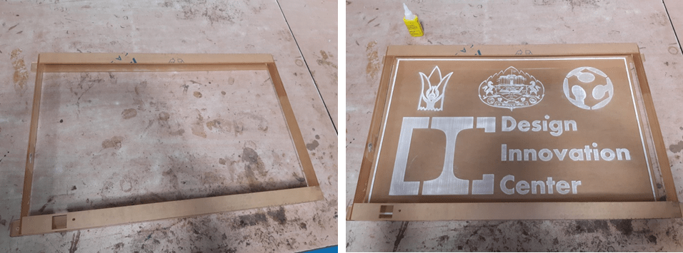
The earlier board was of plywood. It was damaged by the rain. I was given the project to make a new board in place of that board. I talked to Suvarna madam and decided to make acrylic board instead of plywood.
Objective :-
- Make acrylic board.
- LED automation using sensor (LDR & ultrasonic).
STEPS:
1: PROCESS FLOW DIAGRAM
Ideation
2D sketches

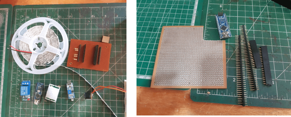
2: MATERIAL & Electronic component.
- Ardiuni Nano
- relay
- adapter 12v/1 am
- adapter 5v/1 am
- LED
- Ultra sonic sensor
- LDR sensor
- Connector
- PCB board
- 2 switch light board
- Pin
- Acrylic
MATERIAL Cost
| Sr. No | MATERIAL | COST | QUANTITY | AVALILABILITY | SIZE |
| 1 | Ardiuni Nano | 250 | 1 | Yes | |
| 2 | relay | 35 | 1 | Yes | |
| 3 | Jumper wire | 20 | 15 | Yes | |
| 4 | adapter 12v/1 am | 130 | 1 | No | |
| 5 | adapter 5v/1 am | 130 | 1 | No | |
| 6 | LED | 50 | 1.5 meter | No | |
| 7 | Ultra sonic sensor | 62 | 1 | Yes | |
| 8 | LDR sensor | 29 | 1 | Yes | |
| 9 | Zero PCB Board | 45 | 1 | ||
| 10 | Female Berg Strip & Male Berg Strip(Connector) | 9 | 1 | ||
| 11 | 2 switch light board | 50 | 1 | NO | |
| 12 | Pin | 5 | 1 | NO | |
| 13 | Acrylic | 500 | Yes | 38cmx58cm | |
| 14 | engraving & cutting acrylic sheet price | 1710 | 1minute =10 Total time – 2 hours 51 minute | Yes | |
| Total – 3025 |
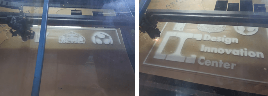
3: DESIGN MODELLING- 2D Design in CorelDraw.

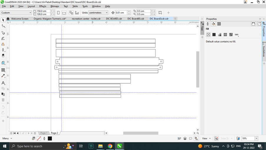
Set up 2D design in RD work software for lager cutter.
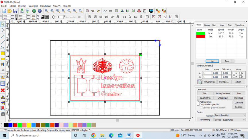
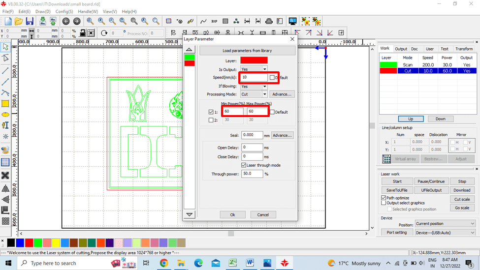
Set cutting power and speed
Set power 60 and speed 10 for cut.
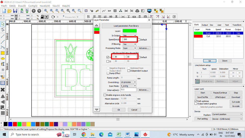
set speed 200 and power 30 for Engraving (scan).
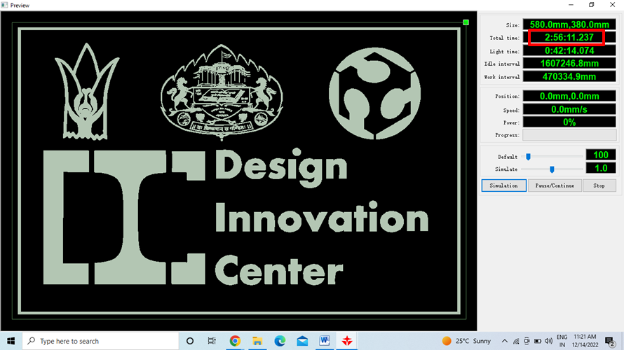
Cutting and Scanning Time
Cutting & scan time 2 hours ,56 minutes for this size 58 cm x 38 cm.
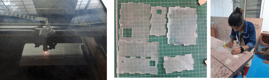
Lager Cutter
This is the monitoring panel of SIL laser cutter.through that we can change different parameters of machine before cutting the materials.
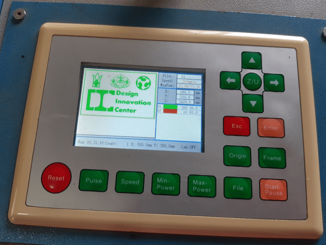
- Placed the material on the bed.
- Set the origin
- Adjust Z axis i.e position of laser head from the material surface.
- Select the file in panel. identify the cutting area with frame.
- Click on start/ pause button.
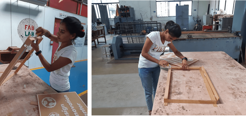
- Border cut for frame.
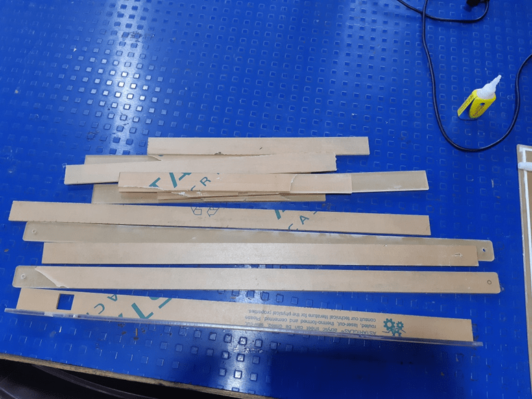
- Made a frame by connecting all the borders with fevikwik.
Electronic Parts
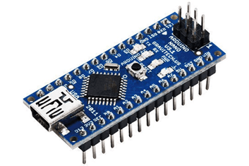
About Arduino Nano
The Arduino Nano is Arduino’s classic breadboard friendly designed board with the smallest dimensions. The Arduino Nano comes with pin headers that allow for an easy attachment onto a breadboard and features a Mini-B USB connector. The classic Nano is the oldest member of the Arduino Nano family boards.
About Ultrasonic sensor
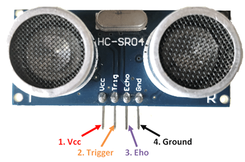
Pin Name
- VCC:- The Vcc pin powers the sensor, typically with +5V
- Trigger:- Trigger pin is an Input pin. This pin has to be kept high for 10us to initialize measurement by sending US wave.
- Echo:- Echo pin is an Output pin. This pin goes high for a period of time which will be equal to the time taken for the US wave to return back to the sensor.
- Ground:- This pin is connected to the Ground of the system.
Ultrasonic Sensor Features
- Operating voltage: +5V
- Theoretical Measuring Distance: 2cm to 450cm
- Practical Measuring Distance: 2cm to 80cm
- Accuracy: 3mm
- Measuring angle covered: <15°
- Operating Current: <15mA
- Operating Frequency: 40Hz
Ultrasonic Sensor – Working
As shown above the HC-SR04 Ultrasonic (US) sensor is a 4 pin module, whose pin names are Vcc, Trigger, Echo and Ground respectively. This sensor is a very popular sensor used in many applications where measuring distance or sensing objects are required. The module has two eyes like projects in the front which forms the Ultrasonic transmitter and Receiver. The sensor works with the simple high school formula that.
Distance = Speed × Time
The Ultrasonic transmitter transmits an ultrasonic wave, this wave travels in air and when it gets objected by any material it gets reflected back toward the sensor this reflected wave is observed by the Ultrasonic receiver module.
Now, to calculate the distance using the above formulae, we should know the Speed and time. Since we are using the Ultrasonic wave we know the universal speed of US wave at room conditions which is 330m/s. The circuitry inbuilt on the module will calculate the time taken for the US wave to come back and turns on the echo pin high for that same particular amount of time, this way we can also know the time taken. Now simply calculate the distance using a microcontroller or microprocessor.
How to use the Ultrasonic Sensor
HC-SR04 distance sensor is commonly used with both microcontroller and microprocessor platforms like Arduino, ARM, PIC, Raspberry Pie etc. The following guide is universally since it has to be followed irrespective of the type of computational device used.
Power the Sensor using a regulated +5V through the Vcc ad Ground pins of the sensor. The current consumed by the sensor is less than 15mA and hence can be directly powered by the on board 5V pins (If available). The Trigger and the Echo pins are both I/O pins and hence they can be connected to I/O pins of the microcontroller. To start the measurement, the trigger pin has to be made high for 10uS and then turned off. This action will trigger an ultrasonic wave at frequency of 40Hz from the transmitter and the receiver will wait for the wave to return. Once the wave is returned after it getting reflected by any object the Echo pin goes high for a particular amount of time which will be equal to the time taken for the wave to return back to the sensor.
The amount of time during which the Echo pin stays high is measured by the MCU/MPU as it gives the information about the time taken for the wave to return back to the Sensor. Using this information the distance is measured as explained in the above heading.(HC-SR04 Ultrasonic Sensor Pinout – Components101)
About LDR Module Sensor
LDR Module Sensor :-
LDR sensor module is used to detect the intensity of light. It is associated with both analog output pin and digital output pin labelled as AO and DO respectively on the board. When there is light, the resistance of LDR will become low according to the intensity of light. The greater the intensity of light, the lower the resistance of LDR. The sensor has a potentiometer knob that can be adjusted to change the sensitivity of LDR towards light.

Features:
- Able to detect ambient brightness and light intensity
- Adjustable sensitivity (via blue digital potentiometer adjustment)
- Operating voltage 3.3V-5V
- Digital switching outputs (0 and 1) -D0
- With fixed bolt hole for easy installation
- Small board PCB size: 3cm * 1.6cm
- Power indicator (Red) and the digital switch output indicator (Green)
- Features wide range voltage comparator LM393
Pin outs:
- External 3.3V-5V VCC
- External GND ground
- DO digital output interface, a small plate (0 and 1)
How to use:
Photosensitive resistor module most sensitive to environmental light intensity is generally used to detect the ambient brightness and light intensity.
Module light conditions or light intensity reach the set threshold, DO port output high, when the external ambient light intensity exceeds a set threshold, the module D0 output low;
Digital output D0 directly connected to the MCU, and detect high or low TTL, thereby detecting ambient light intensity changes;
Digital output module DO can directly drive the relay module, which can be composed of a photoelectric switch; (link -LDR Sensor Module (Light Dependent Resistor), LDR-MOD)
Relay
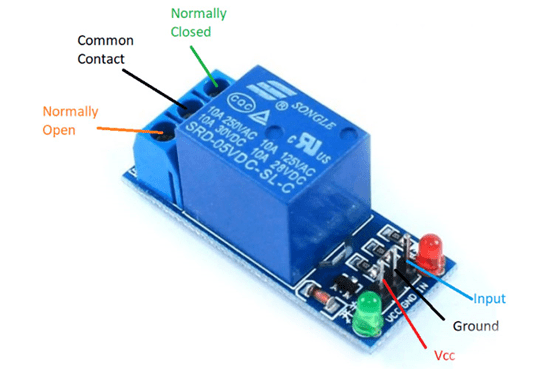
Relay:- Relay is an electromechanical device that uses an electric current to open or close the contacts of a switch. The single-channel relay module is much more than just a plain relay, it comprises of components that make switching and connection easier and act as indicators to show if the module is powered and if the relay is active or not.
Single-Channel Relay Module Pin Description.
Pin Name
- Relay Trigger – Input to activate the relay
- Ground – 0V reference
- VCC – Supply input for powering the relay coil
- Normally Open – Normally open terminal of the relay
- Common – Common terminal of the relay
- Normally Closed – Normally closed contact of the relay.
First of all I checked all the sensors by programming them separately. Checked the sensor is working or not.
Check LDR Sensor:-
Code:-
int LDRpin = 4;
int LDRValue = 0;
int LedPin = 13; // NEW
void setup()
{
Serial.begin(9600);
pinMode(13, OUTPUT); // NEW
digitalWrite(13, LOW); // NEW
}
void loop()
{
LDRValue = digitalRead(LDRpin);
Serial.println(LDRValue);
delay(2000);
if (LDRValue==1) // NEW
{
digitalWrite(LedPin, HIGH);
}
else
{
digitalWrite(LedPin, LOW);
}
}
Checking ultrasonic sensor
Code:-
// —————————————————————- //
// Arduino Ultrasonic Sensor HC-SR04
// Re-writed by Arbi Abdul Jabbaar
// Using Arduino IDE 1.8.7
// Using HC-SR04 Module
// Tested on 17 September 2019
// —————————————————————- //
#define echoPin 2 // attach pin D2 Arduino to pin Echo of HC-SR04
#define trigPin 3 //attach pin D3 Arduino to pin Trig of HC-SR04
// defines variables
long duration; // variable for the duration of sound wave travel
int distance; // variable for the distance measurement
void setup() {
pinMode(trigPin, OUTPUT); // Sets the trigPin as an OUTPUT
pinMode(echoPin, INPUT); // Sets the echoPin as an INPUT
Serial.begin(9600); // // Serial Communication is starting with 9600 of baudrate speed
Serial.println(“Ultrasonic Sensor HC-SR04 Test”); // print some text in Serial Monitor
Serial.println(“with Arduino UNO R3”);
}
void loop() {
// Clears the trigPin condition
digitalWrite(trigPin, LOW);
delayMicroseconds(2);
// Sets the trigPin HIGH (ACTIVE) for 10 microseconds
digitalWrite(trigPin, HIGH);
delayMicroseconds(1000);
digitalWrite(trigPin, LOW);
// Reads the echoPin, returns the sound wave travel time in microseconds
duration = pulseIn(echoPin, HIGH);
// Calculating the distance
distance = duration * 0.034 / 2; // Speed of sound wave divided by 2 (go and back)
// Displays the distance on the Serial Monitor
Serial.print(“Distance: “);
Serial.print(distance);
Serial.println(” cm”);
}
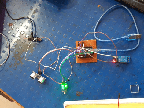
Final connection
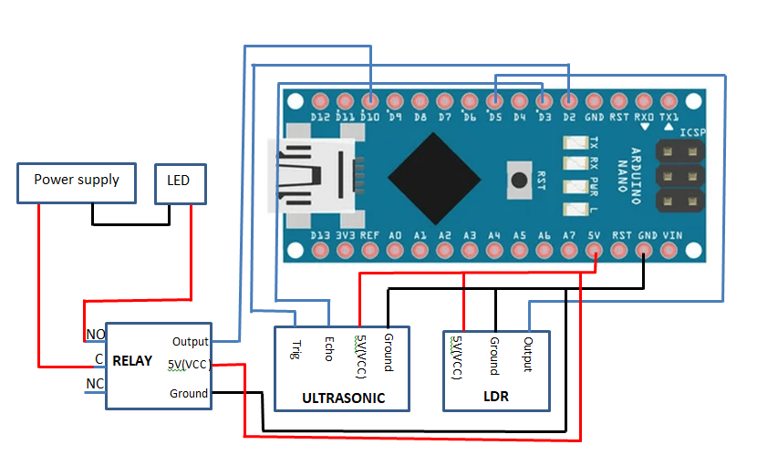
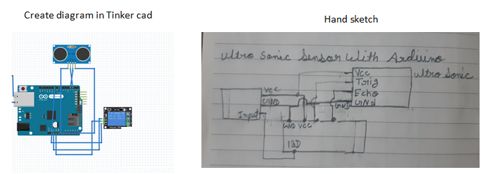
Ultrasonic sensor
Generally, the Ultra sonic sensor has at least 4 pins .
GND (ground) is connected to Arduino GND pin
VCC is the supply pin which is connected to Arduino 5V pin
Trid And Echo pin is serial data line, connected to Arduino Digital pin 2D & 3D.
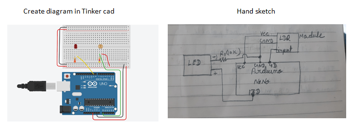
LDR Sensor
Generally, the LDR sensor Module has at 3 pins .
GND (ground) is connected to Arduino GND pin
VCC is the supply pin which is connected to Arduino 5V pin.
Output pin is serial data line, connected to Arduino Digital pin 5D.
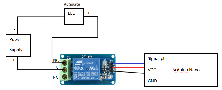
Relay
Generally, the Ultra sonic sensor has at least 6 pins (one side 3 and second side 3).
GND (ground) is connected to Arduino GND pin
VCC is the supply pin which is connected to Arduino 5V pin.
Output(in) pin is serial data line, connected to Arduino Digital pin 10D.
Connect the positive wire of the LED to the normally open of the relay.
Connect the positive wire of the power supply to the common of the relay.
Connect the negative wire of the power supply and the LED together.
working process
Automatic turn on of LED at night
Automatic turn off the LEDs in day
When a person passes in front of the board, the LED turns on for a few seconds.
Code:-Final code
const int trigPin = 2;
const int echoPin = 3;
const int relay = 10;
long duration;
int distance;
int safetyDistance;
int LDRpin = 5;
int LDRValue = 0;
void setup() {
// put your setup code here, to run once:
pinMode(trigPin, OUTPUT); // Sets the trigPin as an Output
pinMode(echoPin, INPUT);
pinMode(relay, OUTPUT);// Sets the echoPin as an Input
Serial.begin(9600); // Starts the serial communication
digitalWrite(relay, HIGH);
}
void loop() {
//LDR value check
LDRValue = digitalRead(LDRpin);
Serial.println(LDRValue);
delay(100);
// put your main code here, to run repeatedly:
// Sets the trigPin on HIGH state for 10 micro seconds
digitalWrite(trigPin, LOW);
delayMicroseconds(2);
digitalWrite(trigPin, HIGH);
delayMicroseconds(10);
digitalWrite(trigPin,LOW);
// Reads the echoPin, returns the sound wave travel time in microseconds
duration = pulseIn(echoPin,HIGH);
// Calculating the distance
distance= duration*0.034/2;
Serial.println(distance);
delay(50);
safetyDistance = distance;
delay(100);
if((distance<70))
{
digitalWrite(relay, LOW);
Serial.println(“Hello stranger”);
delay(3000 );
}
else if (LDRValue==1)
{
digitalWrite(relay, LOW);
Serial.println(“Dark”);
}
else
{
digitalWrite(relay, HIGH);
}
}
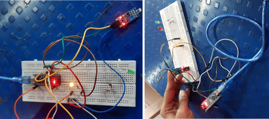
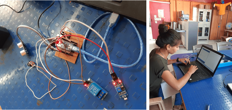
Uploaded and tested the final code with the help of Suvarna madam.
Testing Video
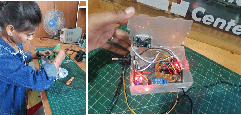
Made a connector to connect all the components to the Arduino.
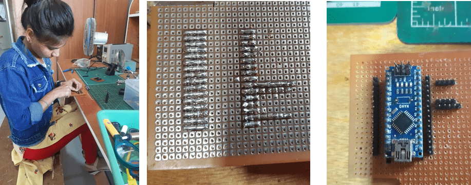
Connect to all component with the soldering.
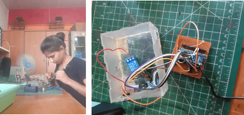
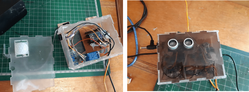
Made a box to set all the electronic components together.
Set all the components together and made the controller for the board.
Fixing the LED strip on the board with the help of glue gun.
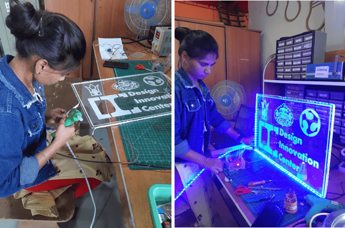
LED Testing
Problem with PIR sensor
The sensitivity range of PIR sensor is between 3m and 7m. The field of view of the sensor is typically 110 degrees. Due to its high sensitivity range, it was also turning on & off the LED of sensing tree there. So I have replaced the ultrasonic sensor with a PIR sensor.
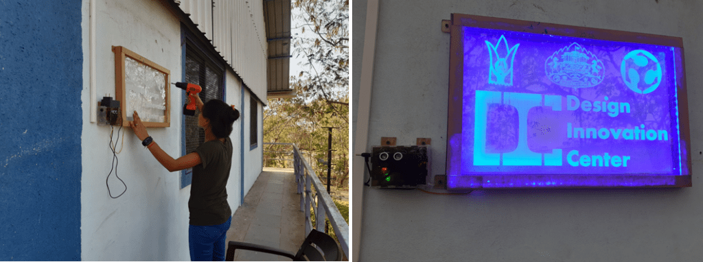
Connected to solar energy and setup a switch board with the help of DBRT student to run on solar energy.
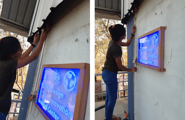
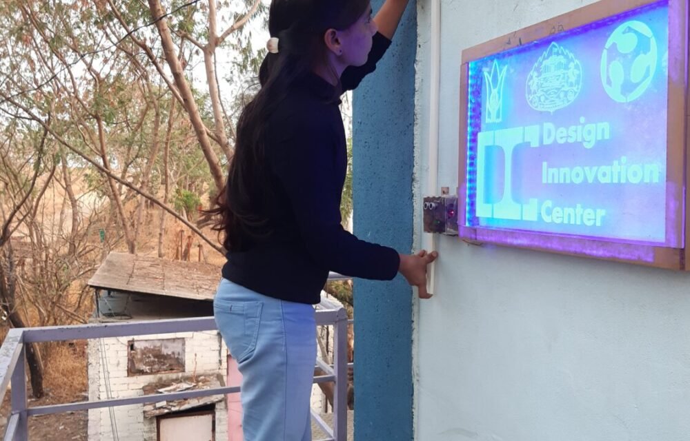
Installed the board on the wall of DIC LAB.
Working video
conclusion:-
During this project I learned about sensor (LDR model, ultrasonic).
Learned to use laser cutter machine.
Learned to use electronics.
Learned about Arduino Nano and used Arduino Nano in this project.


