Introduction
The main gate of Vigyan Ashram basically consists of a lever mechanism with a weight on one side. The gate was operated manually. When the driver has to pass through the gate, he needs to come out of the car, open the gate and after entering the campus he has to come out of the car and close the gate again. This was a very time-consuming process and requires a lot of effort.
The gate was consisting of a 1/2 HP AC induction motor and gearbox of 40:1 reduction ratio.
Feedback of Version 1:
- The microcontroller was affected with the earthing supplied for welding of broken pipe of gate.
- The gate was operated on 1/2 HP motor which is used in elevators and can lift 7 to 8 peoples upward.
- This results in product being over-engineered.
Concept for Barrier Gate System:

Ideation:
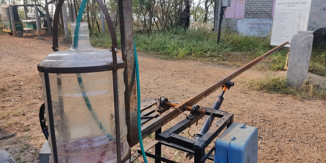
- Using water as balanced weight for the gate.
- Water can be stored in a jar at a weight point of barrier gate.
- Opeining and closing of the gate will be controlled by controlling the level of water in the container.
- The water can be pumped in and out using 18 w pump.

Material Used:
Process Flow Diagram:

Design of Main Lever:
Material Used: MS Square pipe (40 X 20 X 2 mm)
Design:

Design of Jar Holder:
Material Used: MS Flat Plate – 18 X 4 mm
Design:

Trial 1: In trial 1, it was seen that when water in the jar rises up and goes above the equilibrium position, the gate starts coming down and it gets suddenly collides with the ground surface. During the closing of the gate, the lever gets collide with the rest plate.
This was happening due to the addition of resultant forces of the lever to the water balance of the gate as shown in figure.


This leads to a continuous increase of Resultant Load with a continuous increase of Fsinθ and adding it to a Resultant Load…
Concept of Damper:
A shock absorber or damper is a mechanical or hydraulic device designed to absorb and damp shock impulses. It does this by converting the kinetic energy of the shock into another form of energy (typically heat) which is then dissipated.
Working:

- During opening of the gate, there creates vacuum inside the damper.
- This vacuum results in action of atmospheric pressure on the upper side of piston.
- The resultant downward push created due to vacuum inside the damper acts as downward pull for opening gate.

- During closing of the gate, the air present in the damper gets compressed.
- This compressed air pushes the piston in upward direction.
- The resultant push provided by the compressed air acts as opposition force for the downward coming gate.
Proposed Design for Damper System:
\
- CAD Files:
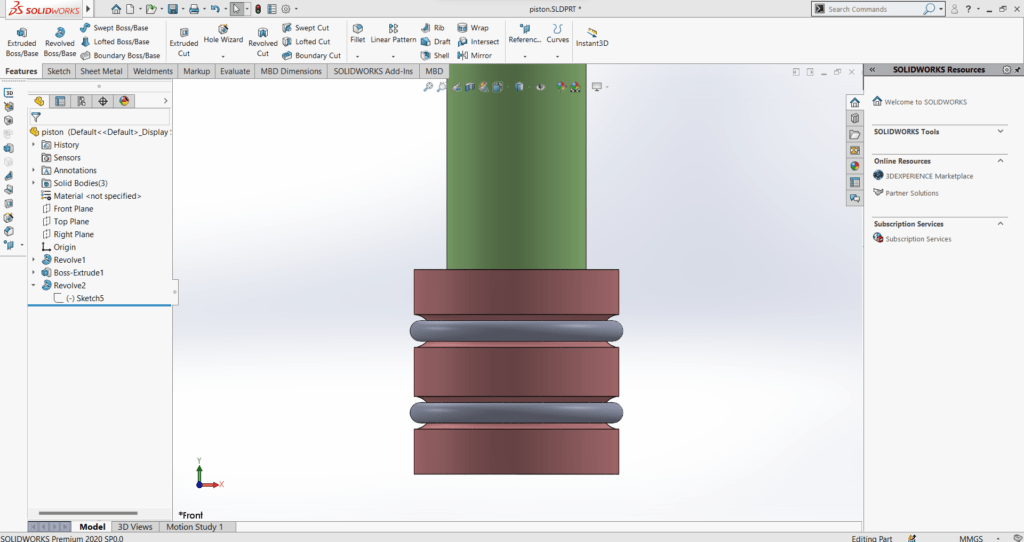
Piston 
PVC Cylinder 
Endcap 
Assembly
- Detailed Part List:
- PVC Pipe
- Endcap
- MS Pipe 25.4mm
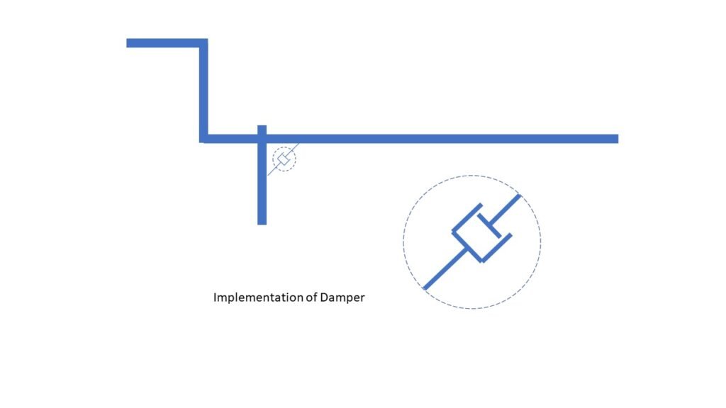
Implementation of Damper:

When the gate is opening the orifice allows a certain amount of air to pass through it. But the resultant load is greater than than the air, so there forms a vacuum inside the damper. This vacuum restricts the upward motion of gate by providing downward pull to a gate.
When the gate is closing the orifice allows less amount of air and due to the weight of the lever, the air gets compressed inside the damper which provides upward restriction to the downward motion of the gate.
Electronics:
Circuit Design:

Code:
#include <ESP8266WiFi.h>

#include "Adafruit_MQTT.h"

#include "Adafruit_MQTT_Client.h"

#define WLAN_SSID       "Workshop"

#define WLAN_PASS       "VIGYAN0030"

#define AIO_SERVER      "io.adafruit.com"

#define AIO_SERVERPORT  1883

#define AIO_USERNAME    "VAGateControl"

#define AIO_KEY         "aio_ZCrs674uVZywEwF2q3JnUL9LINEe"

// Assign output variables to GPIO pins

const int water_pump_in = 13;
const int water_pump_out = 12;

int gate_state = 0;
int timer = 0;


WiFiClient client;     // Create an ESP8266 WiFiClient class to connect to the MQTT server.

Adafruit_MQTT_Client mqtt(&client, AIO_SERVER, AIO_SERVERPORT, AIO_USERNAME, AIO_KEY);        // Setup the MQTT client class by passing in the WiFi client and MQTT server and login details.

Adafruit_MQTT_Subscribe GATE_CONTROL = Adafruit_MQTT_Subscribe(&mqtt, AIO_USERNAME "/feeds/GATE_CONTROL");


void MQTT_connect();

void setup() {

  Serial.begin(115200);

  delay(10);

  pinMode(water_pump_in, OUTPUT);
  pinMode(water_pump_out, OUTPUT);

  digitalWrite(water_pump_in, HIGH);
  digitalWrite(water_pump_out, HIGH);


  Serial.println(); Serial.println();

  Serial.print("Connecting to ");

  Serial.println(WLAN_SSID);


  WiFi.begin(WLAN_SSID, WLAN_PASS);

  while (WiFi.status() != WL_CONNECTED) {

    delay(500);

    Serial.print(".");

  }

  Serial.println();

 Serial.println("WiFi connected");

  Serial.println("IP address: "); Serial.println(WiFi.localIP());

  mqtt.subscribe(&GATE_CONTROL);


}

uint32_t x=0;

void loop() {

   MQTT_connect();

Adafruit_MQTT_Subscribe *subscription;

  while ((subscription = mqtt.readSubscription(5000))) {

    if (subscription == &GATE_CONTROL) {

      Serial.print(F("Got: "));

      Serial.println((char *)GATE_CONTROL.lastread);

       if (!strcmp((char*) GATE_CONTROL.lastread, "ON") && gate_state == 0)
       {

        for(timer = 0; timer < 11; timer++)
        {
              digitalWrite(water_pump_in, LOW);
              digitalWrite(water_pump_out, HIGH);
              delay (1000);

        }
              digitalWrite(water_pump_in, HIGH);
              delay(10);
              gate_state = 1;
              Serial.println("Gate Open");
              timer = 0;

       }

      else if (!strcmp((char*) GATE_CONTROL.lastread, "OFF") && gate_state == 1)
      {
       for(timer = 0; timer < 90; timer++)
       {

              digitalWrite(water_pump_in, HIGH);
              digitalWrite(water_pump_out, LOW);
              delay (1000);

      }
              timer = 0;
              digitalWrite(water_pump_out, HIGH);

              delay(6000);
              for(timer = 0; timer < 153; timer++)
              {
                digitalWrite(water_pump_in, LOW);
                delay(1000);
              }

              digitalWrite(water_pump_in, HIGH);
              delay(10);


              gate_state = 0;

              Serial.println("Gate Close");


        }

      }
    }
  }


void MQTT_connect() {

  int8_t ret;

  // Stop if already connected.

  if (mqtt.connected()) {

    return;

  }

 Serial.print("Connecting to MQTT... ");

uint8_t retries = 3;

  while ((ret = mqtt.connect()) != 0) { // connect will return 0 for connected

       Serial.println(mqtt.connectErrorString(ret));

       Serial.println("Retrying MQTT connection in 5 seconds...");

       mqtt.disconnect();

       delay(5000);  // wait 5 seconds

       retries--;

       if (retries == 0) {

         // basically die and wait for WDT to reset me

         while (1);

       }

  }

  Serial.println("MQTT Connected!");

}Trials:
Instructables for Gate:
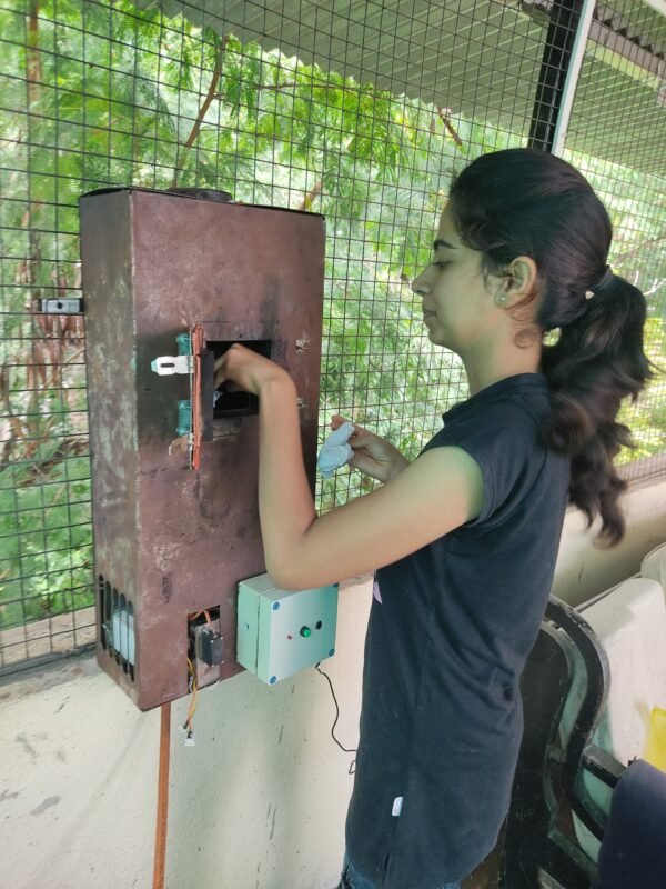
Implementation of Manual Control:

- Manual Control System consists of 2 buttons RED and BLUE.
- To open gate keep BLUE button pressed. The Water will start falling in jar at end of gate. The gate will start opeining.
- To close gate keep RED button pressed. The water will start falling in reservoir of gate.
Feedback:
- The system is working properly and seems conceptual at low cost.
- The process is time consuming and needs more time to close.

