
INTRODUCTION:
The main gate of Vigyan Ashram basically consists of a lever mechanism with a weight on one side. The gate was operated manually. When the driver has to pass through the gate, he needs to come out of the car, open the gate and after entering the campus he has to come out of the car and close the gate again. This was a very time-consuming process and requires a lot of effort.
The gate was consisting of 1/2 HP AC induction motor and gearbox of 40:1 reduction ratio. The system was not functioning well
PROBLEM DEFINED:
The process of gate operation was manual and time-consuming, it also requires human efforts.
TASKS GIVEN:
- To functionalize the main gate of Vigyan Ashram, which was operated manually.
- To operate the gate using Forward and Reverse toggle switch.
- To provide automatic operation of the gate using google assistant of android phone. This allows only authorized person to enter the campus.
- To provide a better asthetic look to the gate.
TASK 1:
To use reverse forward switch for controlling the gate semi-automatically.
The major components includes:
- Single phase induction motor
- Capacitor (100 µ F)
- Change Over Switch

OUTPUT:
- The gate started operating semi-automatically by using change over switch.
Date: 10/07/2021
LIMITATIONS:
- Driver needs to come out of the car for the operation.
- No limit switches included for providing limit to the gate.
- For opening of gate chain was used which used to stuck on the shaft and gate didn’t open.
- Motor covering box was creating lot of noise.
TASK 2:
Step 1: Preparing for circuit diagram of Automatic Control System.
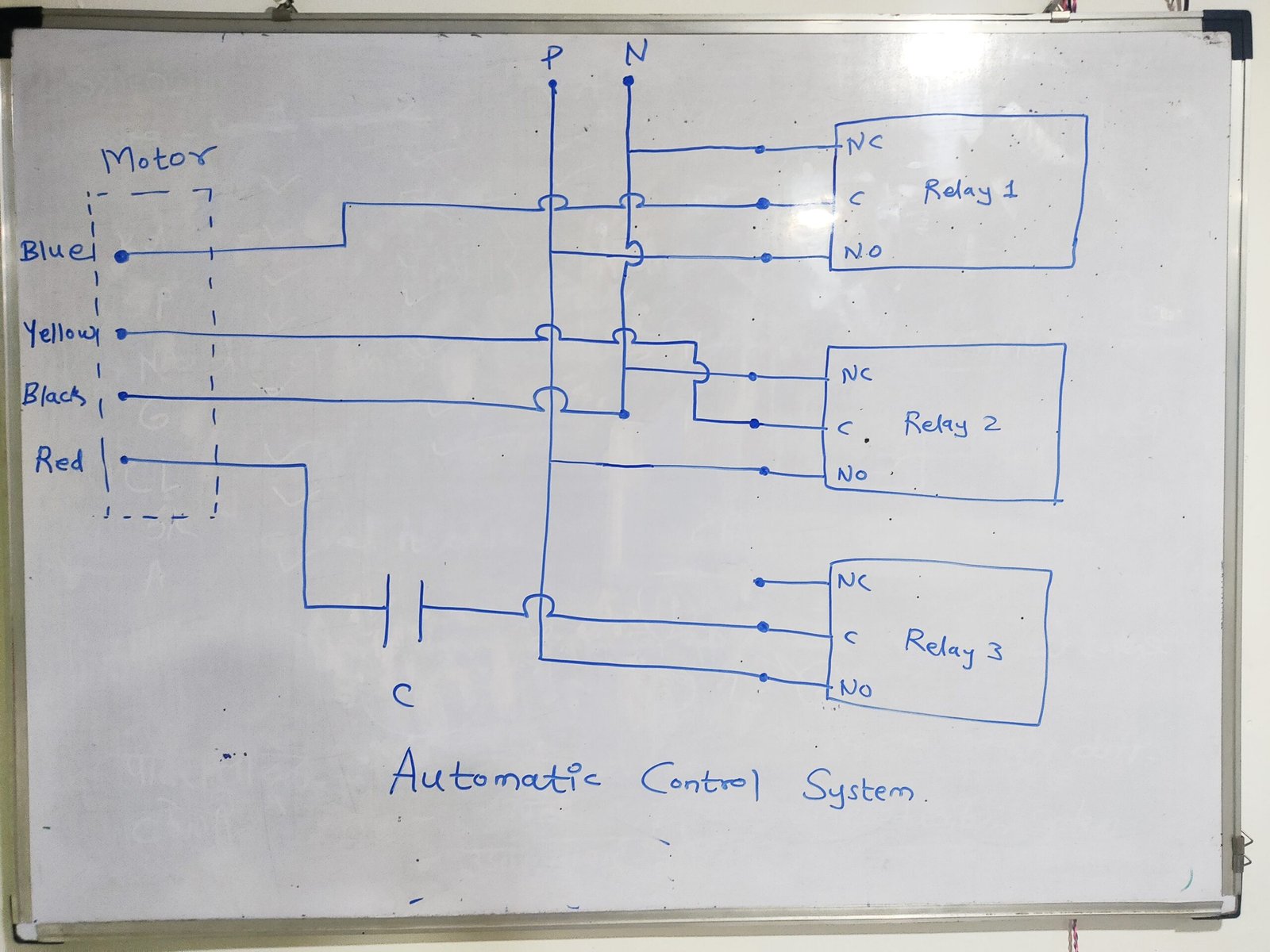
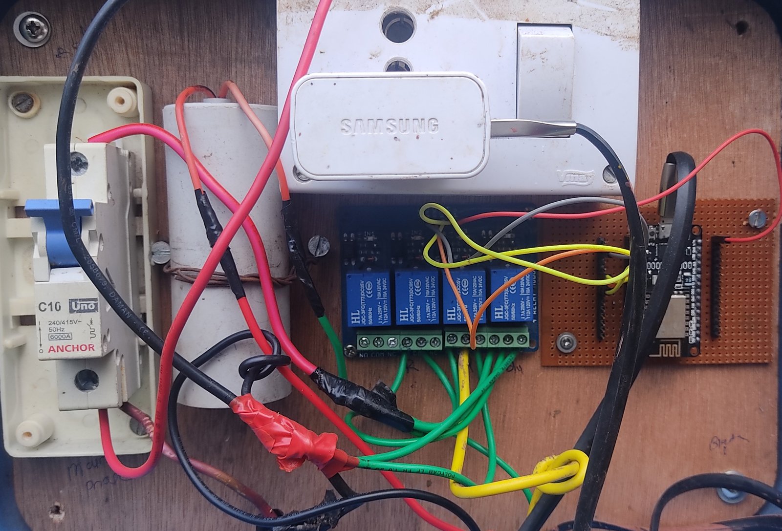
Step 2: Actual Circuit Building.
Connecting all the components according to circuit diagram given above.
The major components include:
- ESP8266 NodeMCU
- DC Power Supply 5V (2 A)
- Relay 4 channel
- MCB
- Capacitor (100 µ F)
- Power Distribution Board
Step 3: Coding the ESP8266 NodeMCU
#include <ESP8266WiFi.h>

#include <EEPROM.h>

#include "Adafruit_MQTT.h"

#include "Adafruit_MQTT_Client.h"

#define WLAN_SSID       ""

#define WLAN_PASS       ""

#define AIO_SERVER      "io.adafruit.com"

#define AIO_SERVERPORT  1883

#define AIO_USERNAME    ""

#define AIO_KEY         ""

// Assign output variables to GPIO pins
const int output12 = 14;
const int output13 = 13;
const int output14 = 12;

int gate_state = 0;


WiFiClient client;     // Create an ESP8266 WiFiClient class to connect to the MQTT server.

Adafruit_MQTT_Client mqtt(&client, AIO_SERVER, AIO_SERVERPORT, AIO_USERNAME, AIO_KEY);        // Setup the MQTT client class by passing in the WiFi client and MQTT server and login details.

Adafruit_MQTT_Subscribe GATE_CONTROL = Adafruit_MQTT_Subscribe(&mqtt, AIO_USERNAME "/feeds/GATE_CONTROL");


void MQTT_connect();

void setup() {

  Serial.begin(115200);

  delay(10);

  pinMode(output12, OUTPUT);
  pinMode(output13, OUTPUT);
  pinMode(output14, OUTPUT);
//pinMode(relay_2,OUTPUT);

 // Connect to WiFi access point.

  Serial.println(); Serial.println();

  Serial.print("Connecting to ");

  Serial.println(WLAN_SSID);


  WiFi.begin(WLAN_SSID, WLAN_PASS);

  while (WiFi.status() != WL_CONNECTED) {

    delay(500);

    Serial.print(".");

  }

  Serial.println();

 Serial.println("WiFi connected");

  Serial.println("IP address: "); Serial.println(WiFi.localIP());

  mqtt.subscribe(&GATE_CONTROL);


}

uint32_t x=0;

void loop() {

   MQTT_connect();

Adafruit_MQTT_Subscribe *subscription;

  while ((subscription = mqtt.readSubscription(5000))) {

    if (subscription == &GATE_CONTROL) {

      Serial.print(F("Got: "));

      Serial.println((char *)GATE_CONTROL.lastread);

       if (!strcmp((char*) GATE_CONTROL.lastread, "ON") && gate_state == 0)

      {

              digitalWrite(output12, HIGH);
              digitalWrite(output13, LOW);
              digitalWrite(output14, HIGH);
              delay (5000);

              digitalWrite(output12, LOW);
              digitalWrite(output13, LOW);
              digitalWrite(output14, LOW);

              gate_state = 1;
              Serial.println("Gate Open");

      }

      else if (!strcmp((char*) GATE_CONTROL.lastread, "OFF") && gate_state == 1)

      {


              digitalWrite(output12, LOW);
              digitalWrite(output13, HIGH);
              digitalWrite(output14, HIGH);
              delay (5000);

              digitalWrite(output12, LOW);
              digitalWrite(output13, LOW);
              digitalWrite(output14, LOW);

              gate_state = 0;
              Serial.println("Gate Close");

      }

    }

  }


}

void MQTT_connect() {

  int8_t ret;

  // Stop if already connected.

  if (mqtt.connected()) {

    return;

  }

 Serial.print("Connecting to MQTT... ");

uint8_t retries = 3;

  while ((ret = mqtt.connect()) != 0) { // connect will return 0 for connected

       Serial.println(mqtt.connectErrorString(ret));

       Serial.println("Retrying MQTT connection in 5 seconds...");

       mqtt.disconnect();

       delay(5000);  // wait 5 seconds

       retries--;

       if (retries == 0) {

         // basically die and wait for WDT to reset me

         while (1);

       }

  }

  Serial.println("MQTT Connected!");

}
Date: 21/07/2021
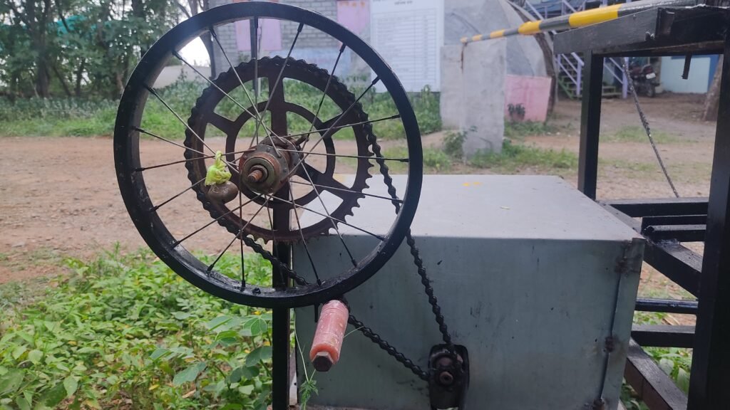
Step 4: Replacing chain with rope in lever mechanism
The problem in the first trial was the stucking of the chain on the shaft during the operation of the gate. This problem was solved by using ropes in place of chains. The rope worked very smoothly in comparison of chains.
LIMITATIONS:
- In absence of electricity, the user need to operate it manually by rotating handle.
- Due to reduction ratio of gearbox user needs to rotate the handle 140 times to open the gate and 140 times again to close it.
- Uneven distribution of the weight on both sides of center axis.
TASK 3:
Increasing the speed and gear ratio of handle for smooth manual operation.
Trial of Handle:
Gate Trials:
Feedbacks :
- When operated frequently and manually the system gets hanged and needs to be reset.
- Problem Identified:
When Gate is Operated the back EMF generated by an induction motor causes the microcontroller to get the hang.
- Solution:
Adding diodes in a circuit avoids back EMF going in the microcontroller through signal pins.

