INTRODUCTION :
Nutrient Film Technique (NFT) is a hydroponics system in which a layer of water is circulated through the channel for a certain amount of time to provide nutrient solution to the plants. The period of circulation of nutrient solution is decided on the basis of requirement of plant. One of the most important benefits of NFT system is that as the roots are suspended in the solution for only a certain interval of time for the rest of the time the roots are provided with abundant source of oxygen.
OBJECTIVES:
- To design and fabricate NFT hydroponics system for Shevanti in DIC lab.
- Implementation of appropriate structure for providing adequate amount of wavelength and intensity of LED lights for the plant growth.
- Providing aesthetic look to the system.
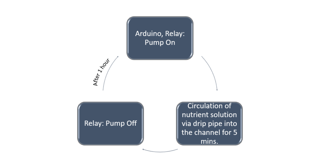
Process Flow Diagram :
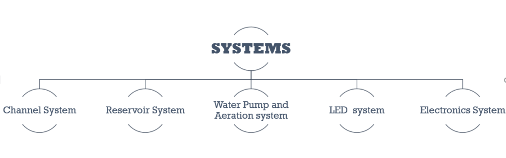
SYSTEMS FOR LED NFT DESIGN:
HAND SKETCHES FOR THE SYSTEM :

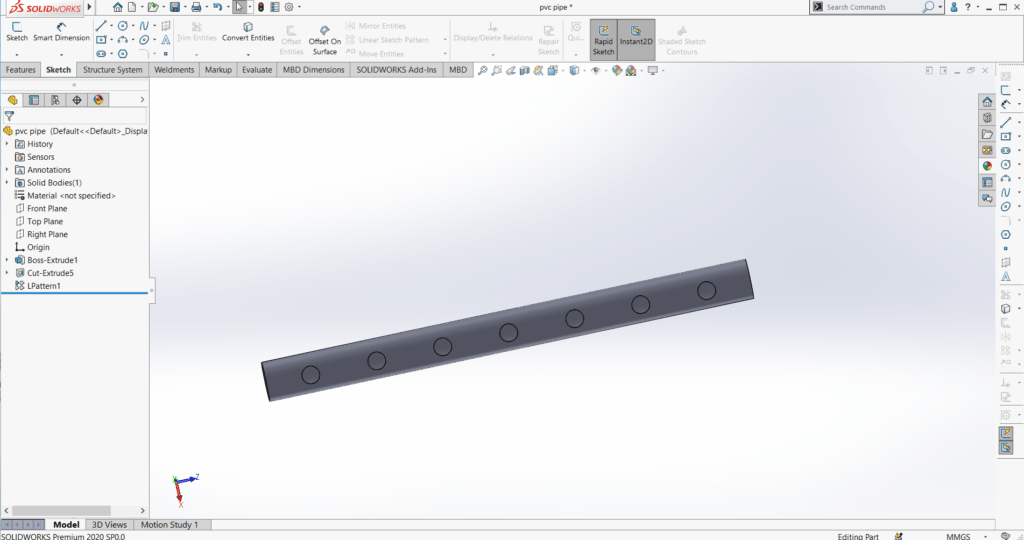
PVC pipe and End cap 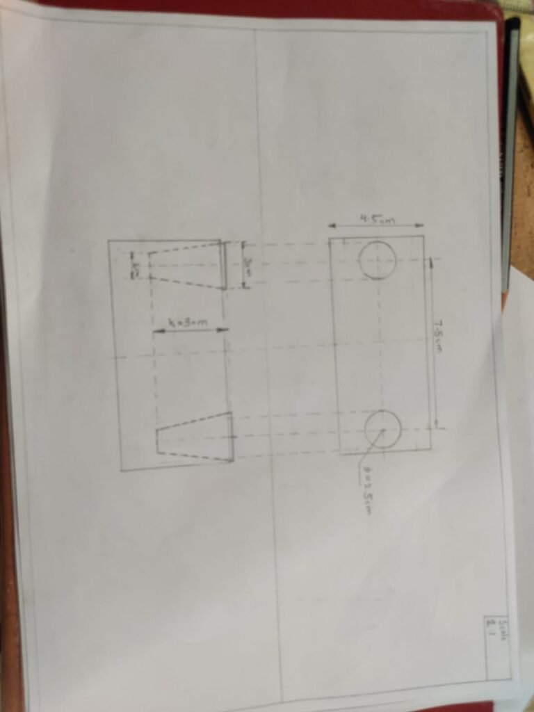
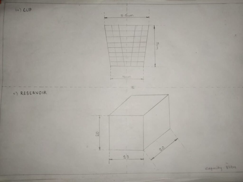
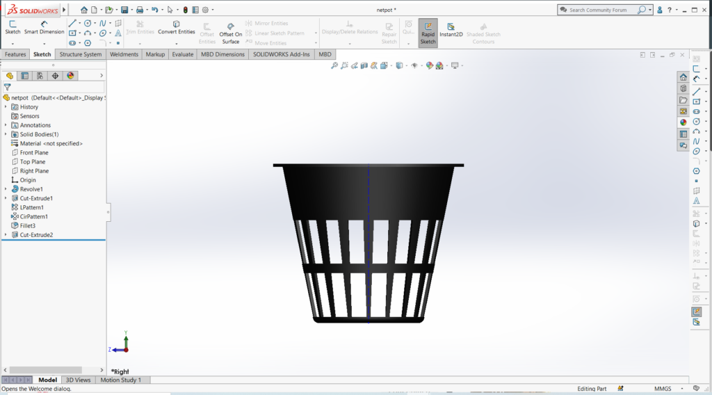
Net pot and reservoir 
Envelope dimensions
Channel is a gully through which the nutrient solution flows, plants take these nutrients from the channel. The roots of plants are suspended in these channels. Our channel system consist of pvc pipe in which 7 holes of 5.1 cm are drilled for fitting net pots of our plant.
CHANNEL SYSTEM :
SUB SYSTEMS
- Channel
- SELECTION OF MATERIAL :
PVC pipe is selected as channel due to following reasons
- Low cost
3 inch PVC pipe is selected considering that we are designing NFT system and if the roots get clogged the channel may not overflow.
- Low maintainance
- Durable and safe
- DIMENSIONS OF CHANNEL :
Length of the channel are decided on the basis of space available in DIC lab.

Above are the envelope dimensions of NFT system.
- Drip Pipe
The solution flows from the reservoir into the channel. For the flow of solution from the reservoir into the channel and then from channel back into the reservoir we have used 16mm drip pipes.
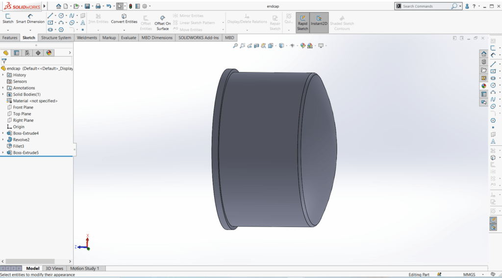
- End Caps
To provide insulation to the PVC pipe from either sides 3inch pvc endcaps are used. At one end of the end cap 16mm hole is drilled for outlet of the solution.
- BILL OF MATERIAL :
WATER PUMP AND AIR PUMP SYSTEM
WATER PUMP : 18 watt aquerium pump is used which gets on after every 1 hour for 5 minutes. Water keeps circulating through the system for 5 minutes per hour.
AIR PUMP : The water in the reservoir can get smelly due to lack of dissolved oxygen(DO). To maintain the DO of water I have provided airation system to the reservoir so that it doesn’t get smelly. It gets on after every 30 minutes for 3 minutes. A air pump is used which is attached to airstone that is placed in the reservoir, it does bubbling of water and thus helps in maintaining the DO of water.
RESERVOIR SYSTEM
Reservoir system is used for holding the dosing solution that is provided to the plants. It is of 30 litre capacity.
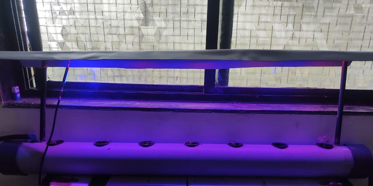
LED SYSTEM
This hydroponics system is design for interior so the plants wont be exposed to direct sunlight. Right amount of exposure of certain spectrum of sunlight is very necessary for the vgetative as well as flowering growth of the plants. Mainly red and blue light contribute to the growth of plant and green light is least needed for the plants. I have used LEDs of blue and red colour.
  WHY LEDs?
LED lights have lower consumption and are available in market in different colours.
- Significane of LEDs used :
RED LED LIGHT : Red light is responsible for making plants flower and produce fruit. It’s also essential to a plant’s early life for seed germination, root growth, and bulb development.
BLUE LED LIGHT : The effect of blue light on plants is directly related to chlorophyll production. Plants that receive plenty of blue light will have strong, healthy stems and leaves.
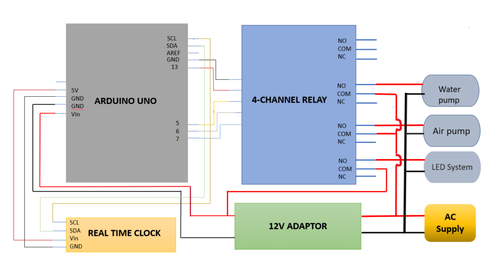
ELECTRONICS SYSTEM :
There are three systems that need to be operated :
- LED SYSTEM: Chrysanthemum needs 11 hours of sunlight and 13 hours of darkness. therefore the leds need to be off for 13 hours. LEDs turns on at 6 a.m and of turns off at 7 p.m. LEDs need 12V DC supply and 2A current.
- AIR PUMP SYSTEM : The dosing solution is stored in reservoir, so it is necessary to provide airation to the solution to maintain its DO. The air pump gets on after every half hour for 3 minutes. It works on AC supply.
- WATER PUMP SYSTEM : The plants are provided with nutrient solution after every 1 hour. The solution flows through the pipe for 5 minute so the water pump needs to turn on after every 1 hour.
Components used:
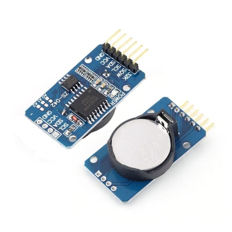
RTC Module 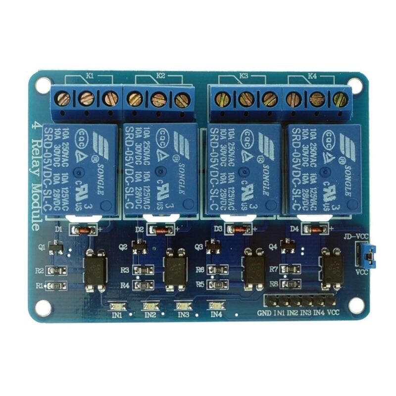
4 – Channel Relay Module 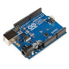
Arduino UNO
ELECTRIC CIRCUIT :
SOURCE CODE ;
#include<Wire.h>
#define RTCAdress  0x68
int ledpin = 13;
int appin =  6;
int wppin = 7;

byte second;
byte minute;
byte hour;

byte bcdtodec (byte val)
{
  return ((val / 16 * 10) + (val % 16));
}
byte dectobcd(byte val)
{
  return ((val / 10 * 16) + (val % 10));
}
void readTime(byte *second, byte *minute, byte *hour)
{
  Wire.beginTransmission(RTCAdress);
  Wire.write(0);
  Wire.endTransmission();
  Wire.requestFrom( RTCAdress , 3);
  *second = bcdtodec(Wire.read() & 0x7f);
  *minute = bcdtodec(Wire.read());
  *hour = bcdtodec(Wire.read() & 0x3f);
}
void setTime(byte second, byte minute, byte hour)
{
  Wire.beginTransmission(RTCAdress);
  Wire.write(0);
  Wire.write(dectobcd (second));
  Wire.write(dectobcd (minute));
  Wire.write(dectobcd (hour));
  Wire.endTransmission();
}
void displayTime()
{
  byte second, minute, hour, day, date, month, year;
  readTime(&second, &minute, &hour);
  Serial.print(hour);
  Serial.print(":");
  Serial.print(minute);
  Serial.print(":");
  Serial.println(second);
  delay(1000);


}
void setup() {
  //put your setup code here, to run once:
  Wire.begin();
  pinMode(ledpin, OUTPUT);
  pinMode(appin, OUTPUT);
  pinMode(wppin, OUTPUT);
  pinMode(13, OUTPUT);
  digitalWrite(13, HIGH);
  Serial.begin(9600);

 setTime(00,05, 13);


}
void loop() {


 readTime(&second, &minute, &hour);
  Serial.println(hour, DEC);
  Serial.println(minute, DEC);
  Serial.println(second, DEC);
  //// put your main code here, to run repeatedly:


  if ((hour >= 6) && (hour <= 18)) {
    digitalWrite(ledpin, HIGH);
    delay (1000);
    Serial.println("LED ON");
  }
  else
  {
    digitalWrite(ledpin, LOW);
    delay (500);
    Serial.println("LED OFF");
    delay (500);
  }
  if ((6 >= minute) && (minute >= 1))
  {
    digitalWrit

    e(wppin, HIGH);
    delay(500);
    Serial.println("WATER PUMP ON");
  }
  else
  {
    digitalWrite(wppin, LOW);
    delay(500);
    Serial.println("WATER PUMP OFF");
  }

  if (((13 >= minute) && (minute >= 10)) || ((43 >= minute) && (minute >= 40)))
  {
    digitalWrite(appin, HIGH);
    delay(500);
    Serial.println("AIR PUMP ON");
  }

  else

  {
    digitalWrite(appin, LOW);
    delay(500);
    Serial.println("AIR PUMP OFF");
  }


  displayTime();
}
Points to be considered while coding :
- RTC takes real time value. so in the code we have to set the time value according to the time.
- The value set in the code must be then uploaded in the arduino.
- After uploading the value we have to comment the set time value and upload the code once again.
Reason for doing this: If we don’t follow the above steps then, if there is powersupply issue then the RTC takes time value which is set in the code instead of the current time value and we may not get desired output.
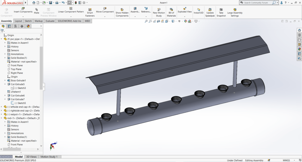
CAD MODELS :
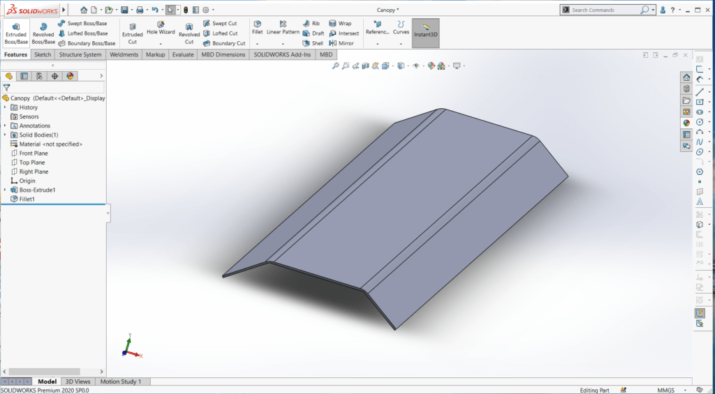


ASSEMBLY OF THE SYSTEM :
CAD MODEL FOR CASING OF ELECTRONICS :

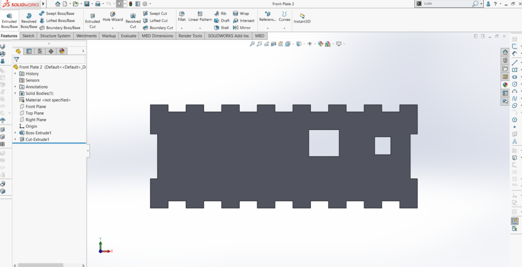

Assembly of Casing :

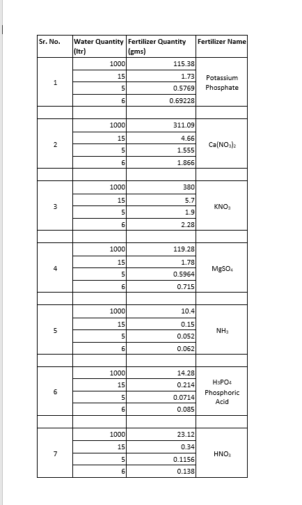
DOSING :
NOTES :
Main issue with the system was of overflowing .The system worked properly for 12 days but after that it started overflowing.
- POSSIBLE REASONS :
- This was due to clogging of roots.
- POSSIBLE SOLUTIONS :
- The input hole and drain hole both were of 16mm. We can increase the size of drain hole so that overflowing issue will be solved.
- If the first solution is not possible then we can change the waterpump to reduce the lpm. Instead of 18W water pump !4 watt Water pump can be used.


