To review the earlier work on plastic belling machine, please refer the following blog.
After testing the previous model of belling machine which has some drawbacks and those need to be changed in the next model as its advancement and learning. The earlier model has leakages at bottom door due to improper sealings. It is not easy to seal the door present at the bottom of the machine or it requires high precision machine equipment.
To tackle with that drawback we decided to make the plunger at the bottom side. So as to avoid leakages from the bottom as it will be fully closed. Additionally we will add bellows around the plunger to make the chamber leakproof.
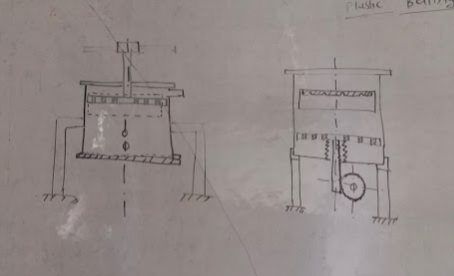
From the concept design it is clear that, we need to make the model in which plunger will be present at bottom side.
Project steps:
- Concept design
- Design for prototype
- Prototype in MDF/Acrylic material
- Check functionality of prototype
- Observe required changes in the design
- Design Modification
- Actual prototype using MS material
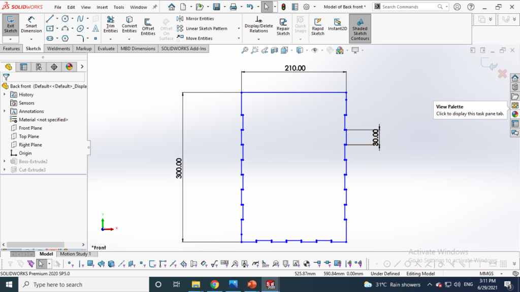
Design for prototype: 22/06/2021 to 28/06/2021

Front & Back side 
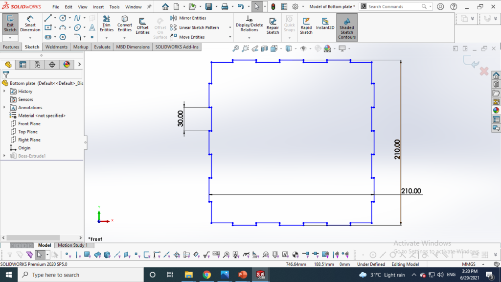
Bottom side 
Left & right side 
Outer shell assembly 
Top door mounting fixture 
Top door 
Upper plunger plate 
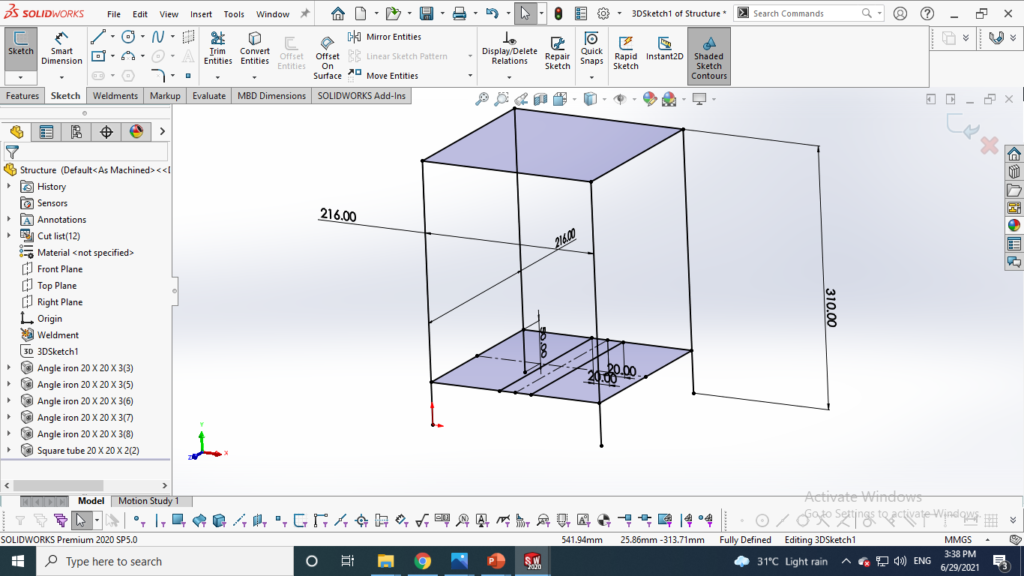
Structure 
Bottom plunger plate 
Spur gear 1 ( Prime mover) 
Lifting rod for plunger
Details:
Front and back side
Right and Left side
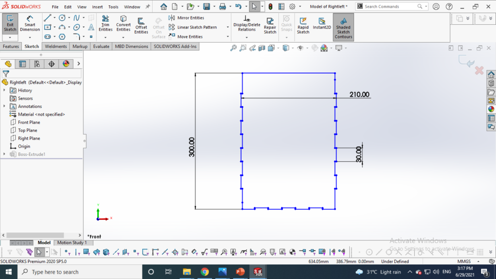
Left & right side
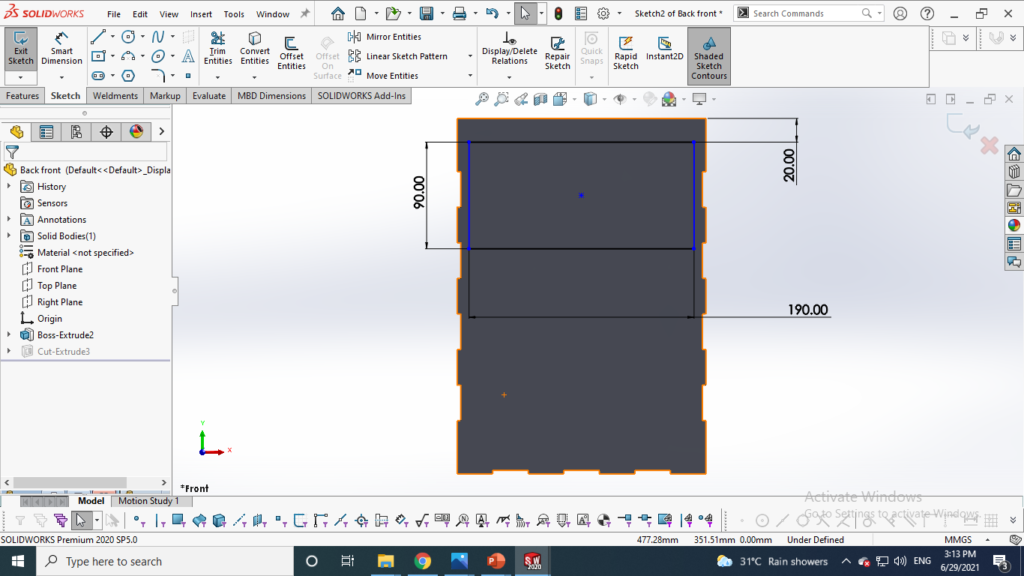
Top door mounting fixture:


Top door


Upper plunger plate


Lower Plunger plate


Structure
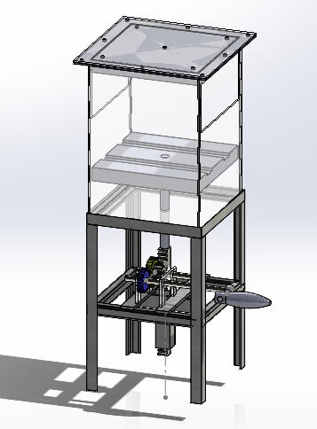
The parts are then joined together and assembled. The complete assembly is shown in following picture.
Fabricating the Prototype:
Our aim is to make a functional prototype in MDF material to check in functionality. So I used
MDF and acrylic material construct a functional prototype. for machining the MDF and acrylic material I used laser cutter for laser cutter we need to create our CAD file into dxf format and then insert that file into RD works software.
Structure is made using available MS material.


Problems: 10/7/2021
The gears and shaft are sized according to market availability and standards of ANSI metric. but It was not considered that it wont be available in acrylic material and also the shaft we used was 8 mm in diameter and the actual hole size was 10mm so even after joining the hole and shaft with filler material (m-seal) it was not fixed due to uplifting weight. It couldn’t successful due to improper material availability.
When the machine is unloaded that time the gears was functioning well but as soon as we tried to load the material the shaft and hole getting failed due to extra play in between them.
So we decided to design and manufacture the parts as per availability and make an operational prototype.
While redesigning the prototype it was decided to design the gear box for certain pressure to be applied on the scrap material. also, the next prototype should be of acrylic material and will be tested in hot water with plastic.
Calculations: 3/8/2021
Plastic carrying capacity: 414 gm
Volume of the container:
V= l*w*h = 20*19*20 = 7600 cm3 =7.6 m3
Density: ρ= m/V = 0.414/7.6 = 0.0545 kg/ m3 This is present density of plastic
Our aim is to compress it in ratio of 1:3
Required force to lift the load of 3.5 kg load (Water, Plastic, connecting rod and rack)
F= mgh
F= 3.5 * 9.8* 0.2 = 6.86 N
P= F/A = 6.86/0.04 = 171.5 N/ m2 = 17.15 Kg/m2
It is recommended that human hand should apply the force not exceed than 45 N
With reference of above calculations designed the gear box to lift the 3.5 kg load.
Redesigning: 4/08/21 to 6/08/21
now the important thing is to design a perfect gearbox who will lift 3.55 kg load, there are virtual virtual simulator websites available on internet, in which we can put our lifting load then it will give the drive size required to lift it.
https://www.nidec.com/en/product/calc/torque/pullup/
With above link I have calculated the drive size required to lift the load.
If we select 70mm Diameter of drive gear to lift the 3.5 kg load it requires 1.19 Nm torque which a human hand can easily apply.

So designed the gear of 70 mm diameter and assembled reversed direction which is closer to the rack to minimize the distance. The earlier position of gear was one after the another so the radius is more, now by changeing the position of gear the Radius is minimised so that the more torque can be applied.


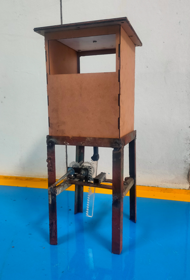
Final assembly


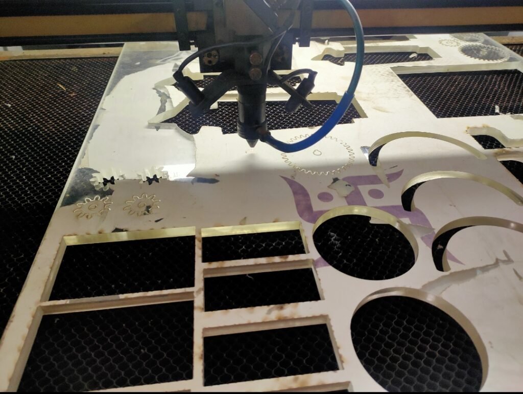
Fabrication:
All the parts were created converted into dxf format and digitally fabrication using laser cutter
The assembly:
The digitally fabricated parts assembled, the acrylic material box sealed with silicon sealant to make it leakproof. As the operation need to be done water.

Gear assembly 
Bellows

body sealed with silicon 
Outlet tap

gear mounting brackets 
rack guide

gear frame mounting 
structure

Outlet door 
guide pin for shaft

Final assembly
After completing the assembly we took the 1st test on 270 gm plastic, the gear failed due to slipping. The keys were not properly inserted in the gears.
Then I redesigned the keyholes and shaft key way and fabricated accordingly. Now gears are not slip.
Trail 1

Raw loaded plastic 
on applying pressure 
Gear slipped during application of pressure
Learnings from trial 1:
All the mechanical joints should have their required constraints, all the mechanical gears and racks should have the guide so that it could travel along its fixed directions.
from the learnings of the 1st trial we designed the guides for gears and rack, cotter pins for shafts.
Trail 2:

before compression 
after compression
Results:
Plastic: 370 gm
Initial volume of plastic: 20*21*21 = 8820 cm3
Initial volume taken for raw plastic before heating it into water at 90 °C, we got only 2 cm compression.
Then plastic pored into 90 °C hot water and let it to be soften for 5 minutes then it transferred to our baling machine. On applying pressure the soften plastic compressed by 10 cm.
the final volume after baling:
10*21*21 = 4410 cm3
Total reduction in volume: 8820-4410 = 4410 cm3
Compression percentage:
4410/8820 = x / 100
x = 50% , therefore 50% reduction in volume.
that of density:
Initial density of 370 gm plastic: Cold press:
rho= m/v = 370/8820 = 0.0419 gm/ cm3
Final density hot press:
rho= m/v = 370/ 4410 = 0.0839 gm/ cm3
the compression ratio is 1:2
Design modification using mechanical guides:


The project is to be handover to Ganesh Khambat for further work.