Introduction
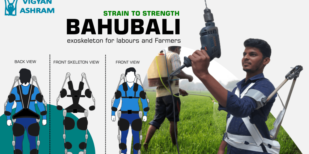
Physical work at industry or farm is very laborious and exhausting, which may be leads to several muscle and bone health issue. Working on repetitive task for hours will leads to muscle pain, and if the work is continued for weeks and months and years the worker may face a muscles health related issue. Which makes natural movements restricted. Which are called as work-related musculoskeletal disorders (WMSDs). So moto of the project is to reduce the human efforts while working in any sector with heavy and repetitive work.
Problem Statement
Reduce the fatigue and efforts required to do the repetitive and exhaustive task in farming industry.
Literature Review
Studied the ongoing research and technical advancements in the field of exoskeleton, although we all think IronMan is hypothetical but with advancing technologies we are ready to make one with limited capabilities. Here i am providing some of the links to refer.
HAL (Hybrid Assistive Limb) by cyberdyne.
Although different exoskeleton are designed for specific reason, we are trying to implement one in the agricultural sector where verity of work is to do on daily basis. But we found a common point the stress points are there, while working in farm stress is continuously exerted on lower back. So First a fall our aim is to design supportive system for bicep, shoulder, lower back and then knees.
Concept
A spring loaded passive exoskeleton which will reduce the efforts from one muscle and hence reduce the fatigue on that muscle, basically we are distributing some of the stress over another muscle, And we try to link different modules of exoskeleton in such a way a part of stress will be directed on the base i.e. ground.
Visit to Comau
Visiting comau helps us to understand the concept we are thinking is actually working and we can move on the theory we have built.
Proof of Concept
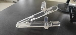
Material selected for the prototype Version 0.1 was 12 mm acrylic because of ease of availability and less time expenditure.
Used readily available crank spring and some of the screws.
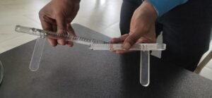
Mechanism tested by fixing it over forearm and bicep with the help of Velcro tape. While testing it is found that mechanism is giving support to the bicep while lifting the load, but design of strap need to improved.
Model design.
Designing the first model for the forearm and bicep support system was completed, with consideration of the spring placement.
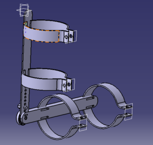
Search for available hand calipers or braces
Instead of manufacturing entire assembly the idea was to search for available braces and directly implement spring mechanism. So contacted Orthosis Mr Deepak at shivajinagar so to take look at available mechanisms.
Discussion with orthopedic doctors about the idea.
Personally met Dr. Pote at shikrapur and Dr. Date at narhe. Got some of the trickiest movements to be considered while going forward to work with exoskeleton. And found out the assumption of the stressed areas made was correct for Knees and lower back and in forearm bicep and shoulder in some specific areas.
First Working Prototype.
After completing first design we started to built first working prototype.
Stages involved in the making the prototype are listed below.
- Found the suitable spiral spring with little bit of calculation and little bit of intuition.
- Found the suitable material, had selected 3mm thick and 25 mm broad MS plate in the design by considering to lift around 5-7 KG of weight.
- Welded the Nut on the bicep plate, with slot of 1mm made at its center to fix the spring.
- Fixed the center of the spring in the groove, and connected the forearm plate with bicep plate.
- Again connected Bicep plate with spring at its extreme support with rivet joint.
- Used custom made cushions for supporting the arm, and pasted Velcro at required position for tightening or loosening strap purpose.
Testing the working and experience of the first prototype.
prototype overview.
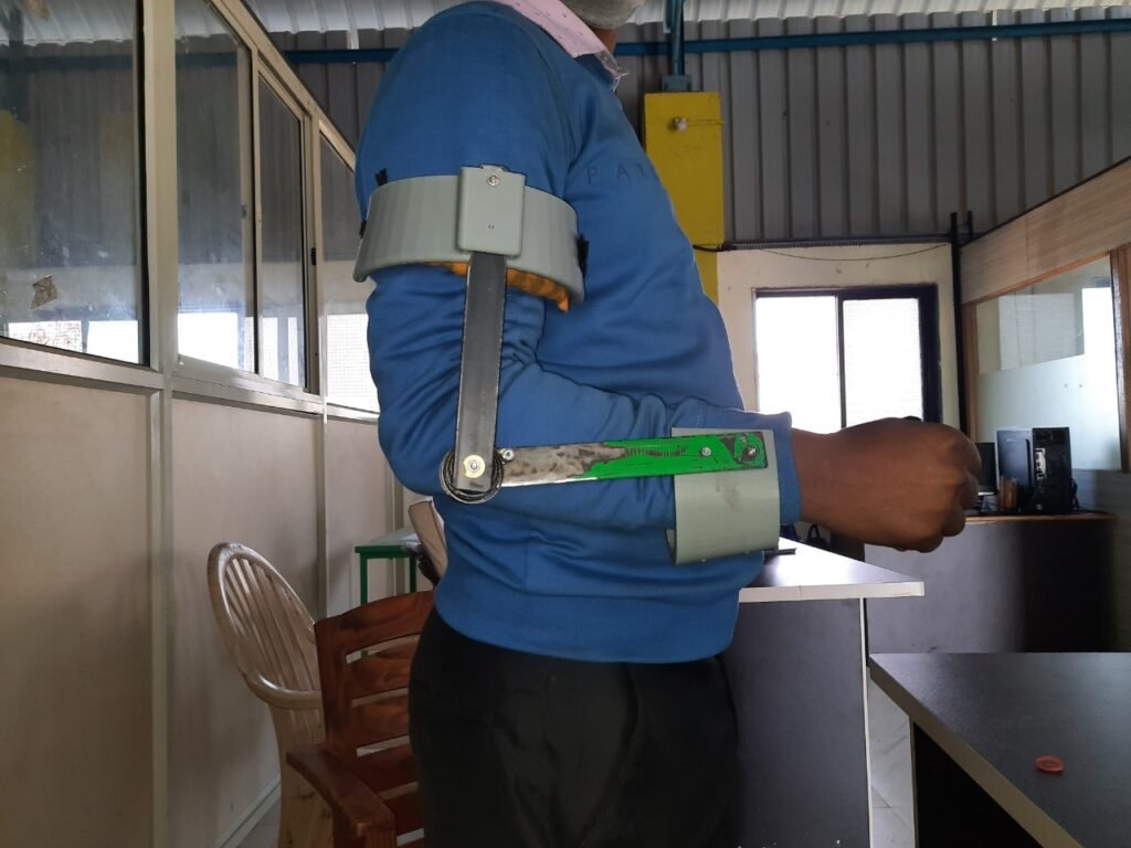
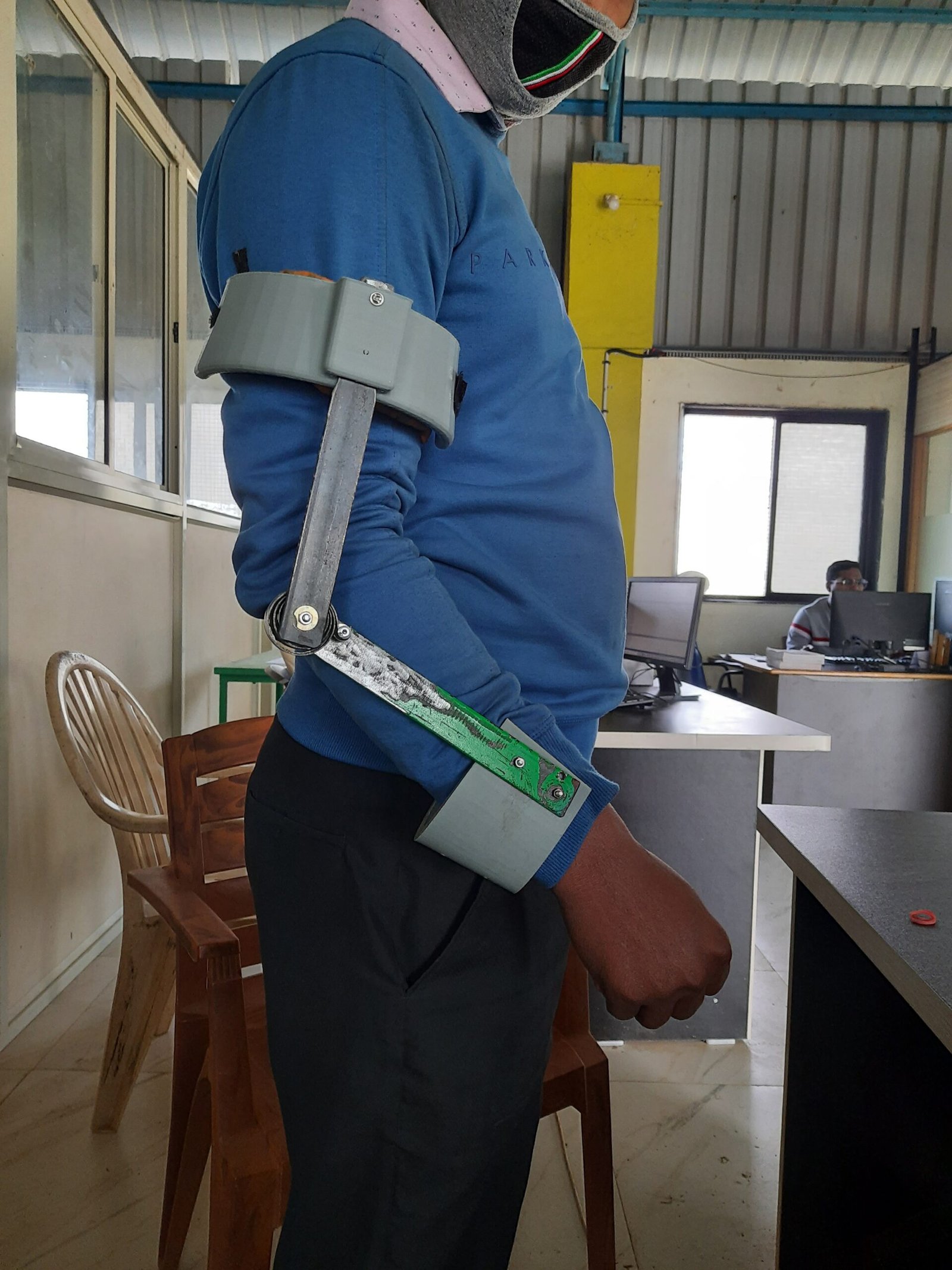
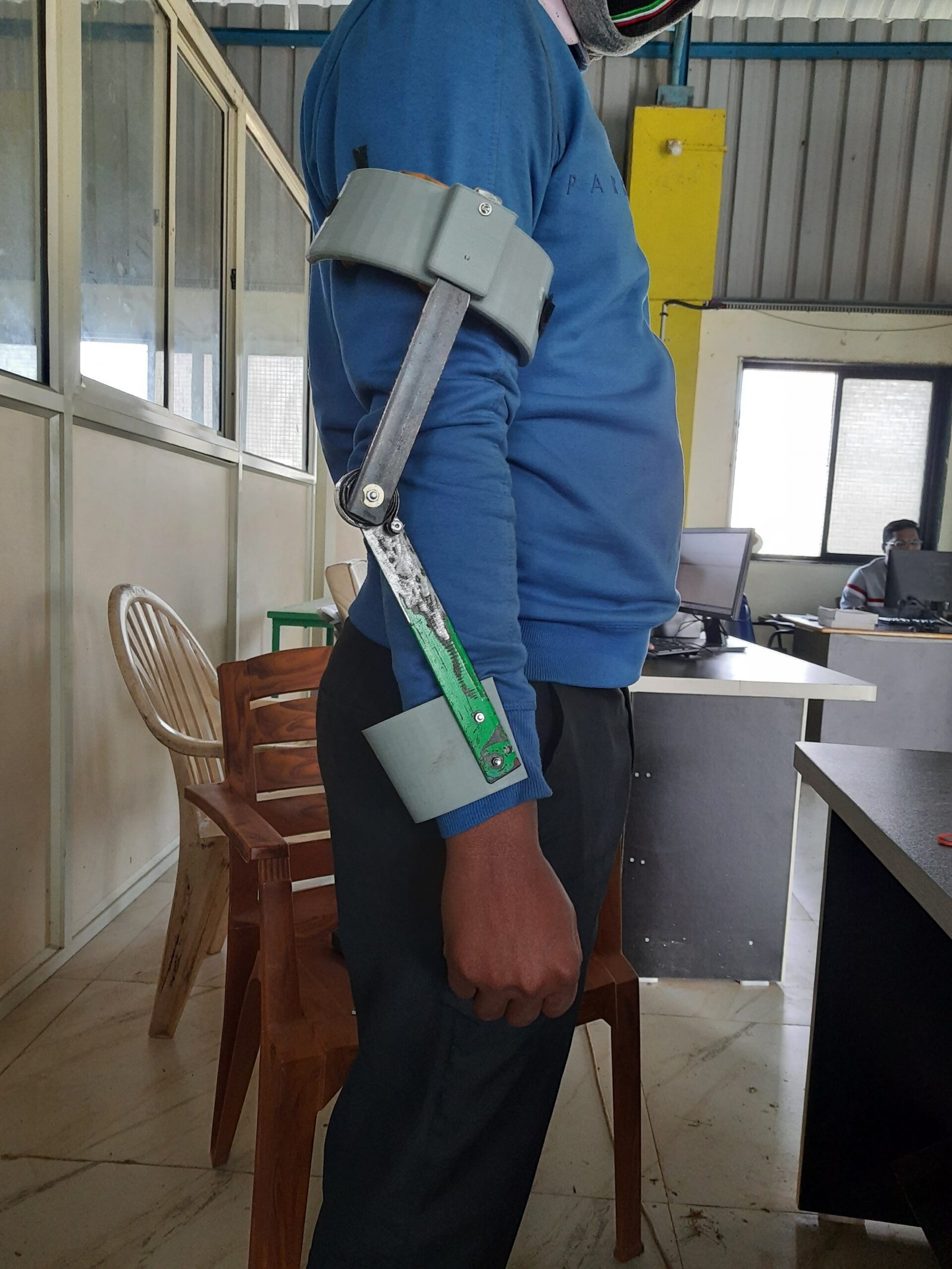

Experience
Prototype posses following advantages.
- It gives support when we want to lift something with the use of bicep muscles.
- It moves with our hand so do not restrict the relative motion between forearm and bicep.
- It do not introduce any lag in motion.
It have disadvantages too.
- It do not permit relative motion between forearm and wrist.
- sometimes strap at bicep get loosen so introducing inefficiency while lifting load.
- forearm support sometimes hurts little bit.
- 2 standard springs used to support only arm of aprox 800 gms.
Improvement Needed.
- Need to modify the Hand supporting brace designs so they don’t hurt.
- Need to calculate the load for specific work and calculate the dimensions of the spring accordingly.
- Need to modify bicep supporting brace to reduce sliding over bicep.
Experiment
Now we need to setup Standard Operating Procedure.
Here in following images we can see what are the variables need to be constrained to get the proper and accurate results.
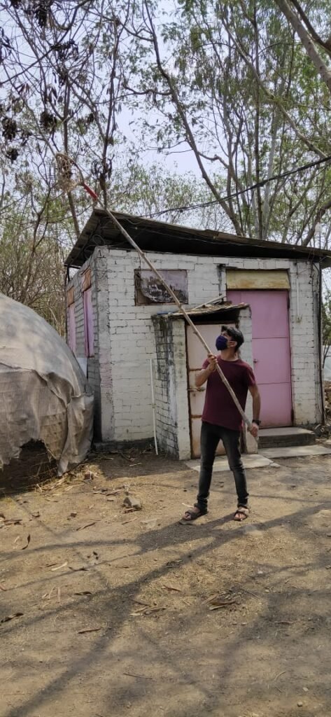
So here are the defined variables needs to be considered.
- Position of the foot of the subject.
- Position of the end point of the Bamboo Stick.
- Gesture of the subject.
- Subjects head position.
SOP for the experiment.
- Constrain the foot position of the subject.
- Constrain the End point of the bamboo stick.
- Set standard position where maximum load will be carried by the bicep muscles.
- Make subject to look towards fruit and once towards camera.
- Note down the endurance limit of each subject individually in seconds.
- Repeat the experiment with exoskeleton.
- Note down the endurance limit of each subject individually in seconds.
- Compare the results.
- Conclude or repeat the experiment with reinvented variables.
Re-designing and printing of the parts.
Here while setting SOP we found some issues which needs to be resolved.
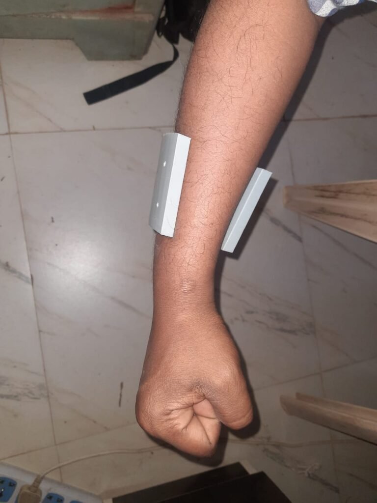
- Design of the forearm and bicep support as the previous one was pinching.
- Last image below shows the tolerance provided to easily rotate the forearm and will not pinch or scratch on the the skin anymore.
- Now cushioning is need to be provided to ensure maximum usability.
- Velcro needs to be used for strap for holding support at its place.
Spring redesign and assembly.
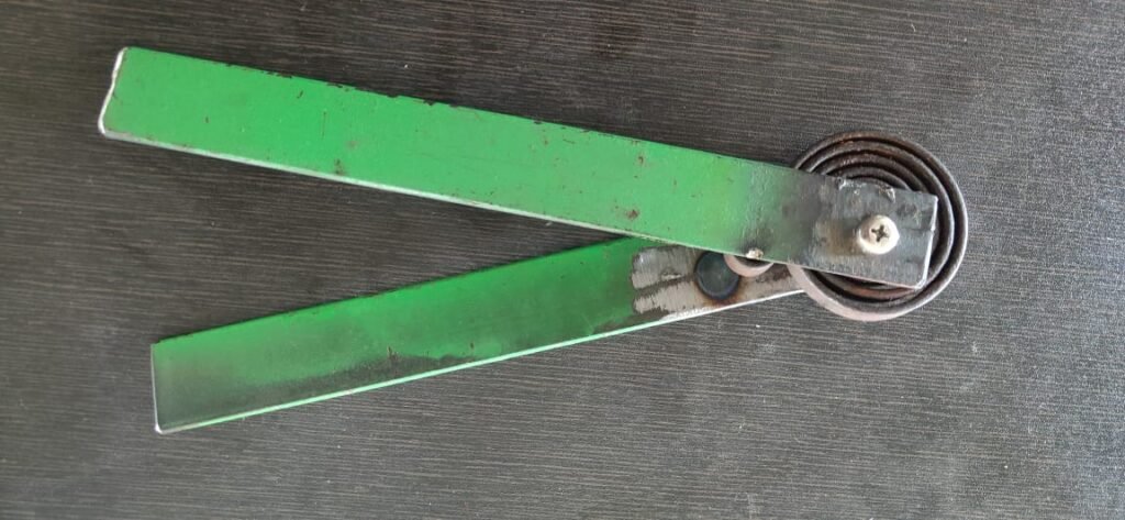
We have used two steel springs for supporting the forearm in one prototype, now we need to design a single spring which will give the same force. following actions has been performed to select the suitable spring.
- Practical exertion of the force by the springs is measured and it id 800 grams .
- Steps needed to follow to achieve the same force with one spring. (i.e. increase in thickness and breath of the spring to match the combined thickness and breath.
- Simulation of the springs with calculated dimensions.
- Assembly of the newly purchased spring with version 2 mechanism.
Limitations of the new spring.
- Newly designed spring deform when the same amount of displacement is done, but providing the force twice as that of previous springs.
- While iterating with the spring dimensions limitation of simulation are there as we did not get the accurate and desired results.
- Contacted different supports for getting accurate analysis, but still issue is not resolved.
Next steps
- Cushioning needs to be provided to the newly designed parts.
- Setting the experiment with the version 1 prototype with redesigned parts.
- Collecting the Experiment data.
- Studying the ways to simulate and analyze the spring.
- Finding support for simulation of single part and complete model.
Participation in Fabcare16 challenge. (9th Aug-14th Aug)
This challenge was done in the FabCare Fab16, FabFoundation and the MakeOpeadics Project
https://matrix-gruppe.de/blog/2020/11/30/makeopaedics/
Fabcare16 challenge gave us opportunity to take our project to the next level. We already made a prototype for Forearm but now we need to shift on the next upcoming part that is shoulder joint.
Here we have our day to day Challenges we have completed/ milestone achieved.
Day 1: Empathies. 11/08/2021
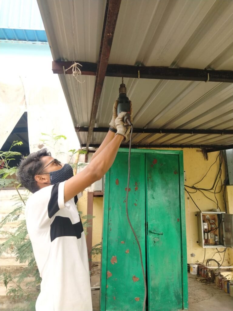
On the very first day we have to generate empathy for our customers, so instead of going somewhere else we choose to inspect our workplace i.e Vigyan ashram.
We found multiple areas where the working person is facing fatigue due to repetitive work, at our campus we rarely need some person to do the repetitive work, but similar kind of works are happening in the farming sector, and industrial sector the workers need to do same repetitive task for 6-8 hours a day and for at least a week for farming sector or may be multiple years in the industry.
Day 2: Ideation 12/08/2021
We had gone through different designs which can be implemented for the support system mentioned below.
Spiral spring based system.
This system uses spiral spring to store the potential energy due to weight of hand into spring as it gets wind and unwinding the spring will give the supportive force to the arm.
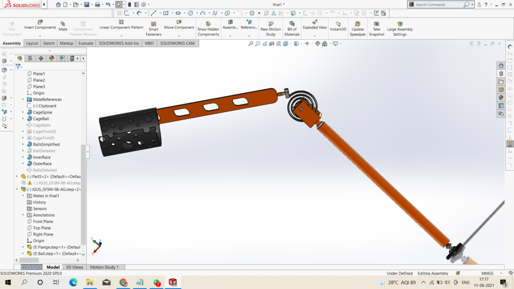
Pneumatic Cylinder based system.
We all knows air is compressible and so it can store the energy, this principle used in the air suspension for the heavy vehicle but here moto of compressing air is storing the energy instead of providing suspension to the system.
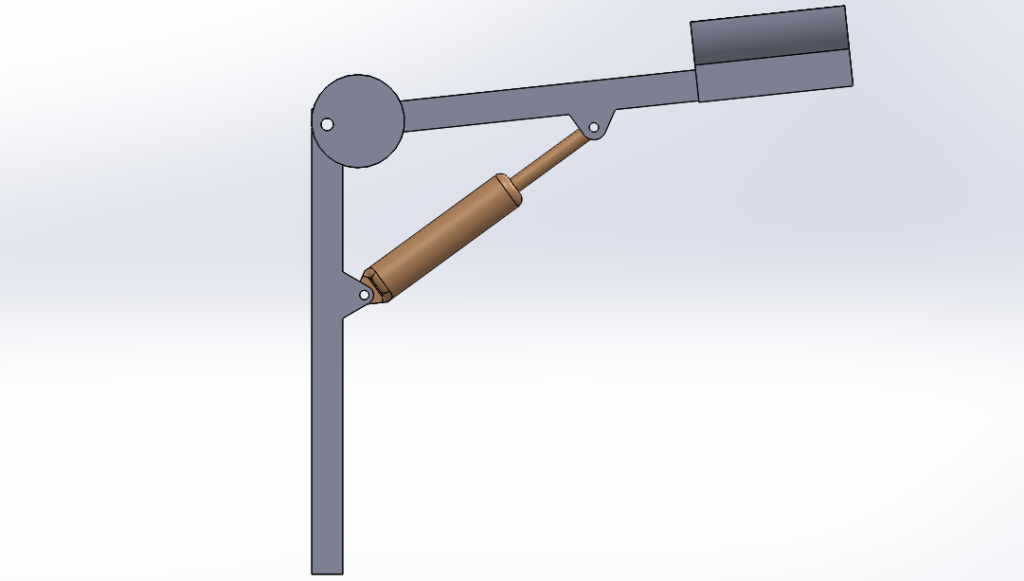
The Compression spring will be working on the same principle as that of the pneumatic cylinder but with less friction and so the design will be the same.
Day 3 : Prototyping and fabrication 13/08/2021
After the brainstorming with the team and checking the availability of the material we decided to work on Spiral spring based design as the system was easy to built and the required parts are readily available.

Our team worked so hard to get the prototype ready.
We used 12 mm metallic rod 2 no with approx. 30 cm length, a spiral spring with 1 mm thickness 10 mm of width, internal diameter 6 cm outer diameter 12 cm and number of turns were 6 in unstressed condition. in stressed condition our number of turns was 9.
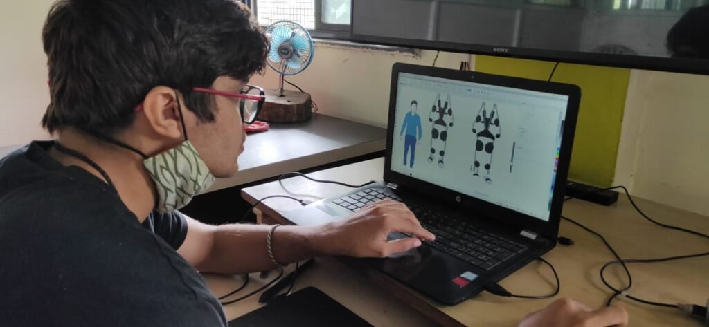
Day 5: Presentation 14/08/2021
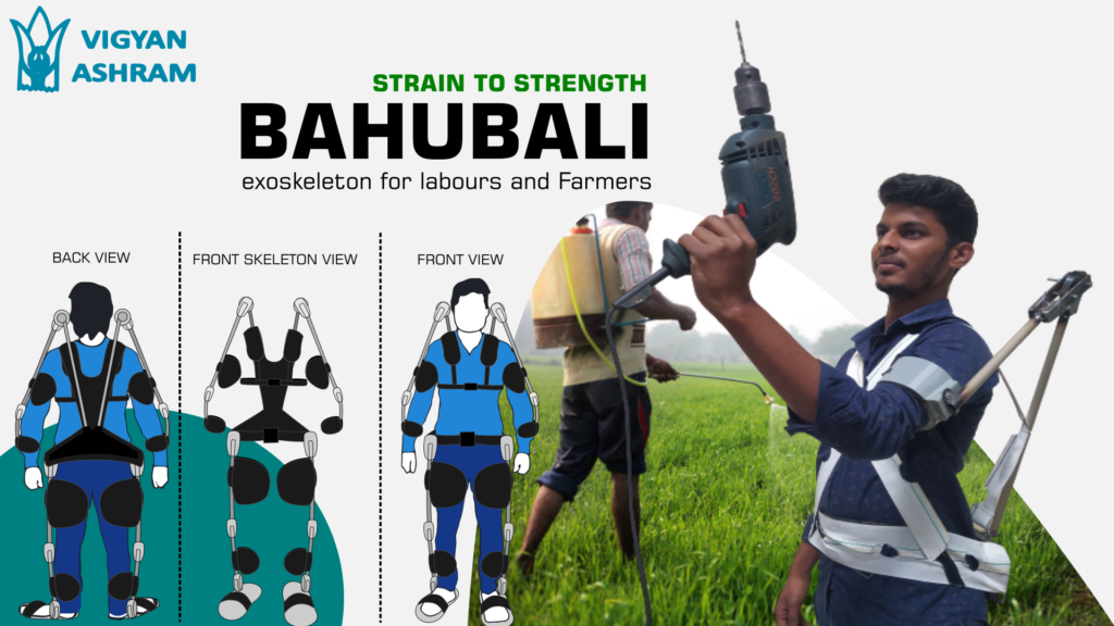
Great, till now we were focused an developing a solution and this were the most challenging and engaging days.
We did it all right now the focus was presenting the solution.
I am inserting here a presentation which we presented.Untitled
Announcement of winner at 3hr.41min.53sec https://www.youtube.com/watch?v=cv8Ghrm-lIU
Returning back on the Forearm POC 16/08/2021
After Completing the challenge Now i am back on the forearm exoskeleton so our current design delivers about 800 gm of assistive force, but our target was around 2.5 kg so we implemented stronger spring then the previous. Currently it is giving the assistive force of 2000 gm or say 2 kg.
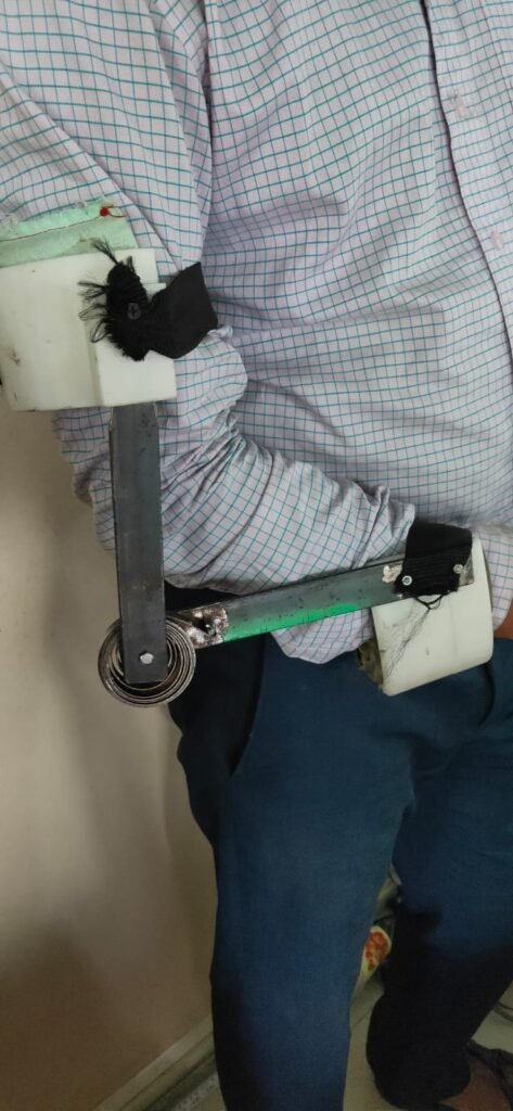
Designing the Spring holder box for the readymade hand caliper. 24/08/2021
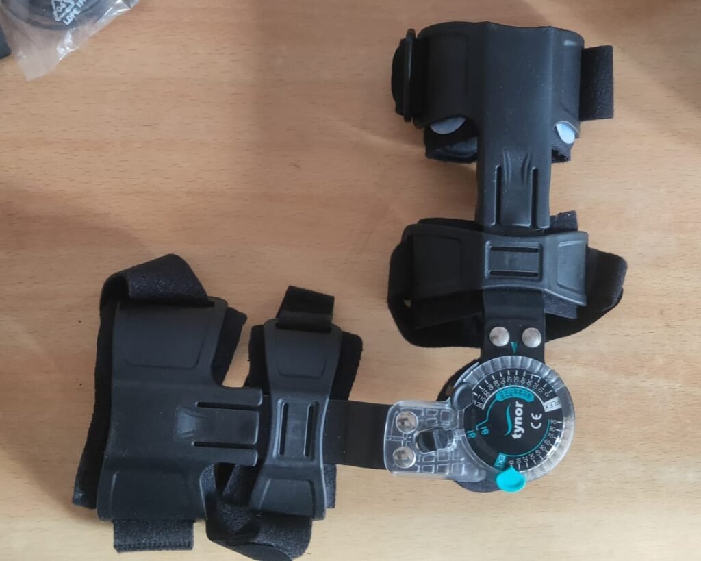
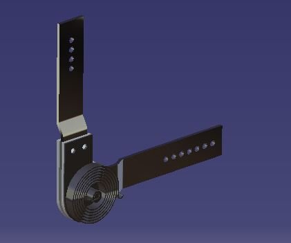
Modelling the available caliper. 15/09/2021
Modelling the available caliper was an important step to get the actual dimensions of the caliper so that the spring holding mechanisms could be designed to fit over the forearm caliper.
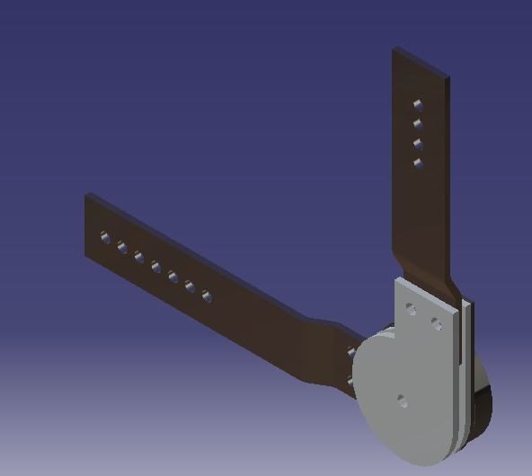
Fabrication of the model.(21/09/2021)
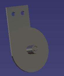
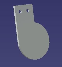
We decided to use plasma cutting machine to cut the plates, and weld a 8 mm screw on it to make the arbor for the spring.
Hence here are the two plates we cut on plasma cutting machine.
Assembly of spring holder mechanism.(27/09/2021)
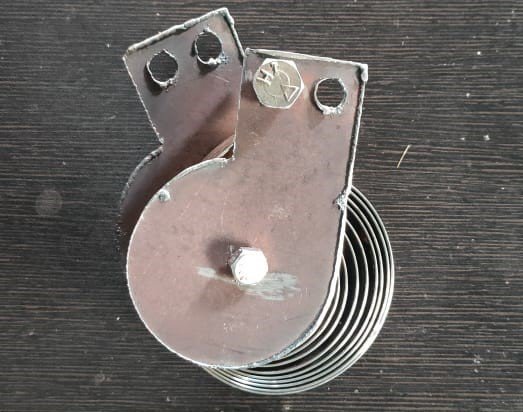
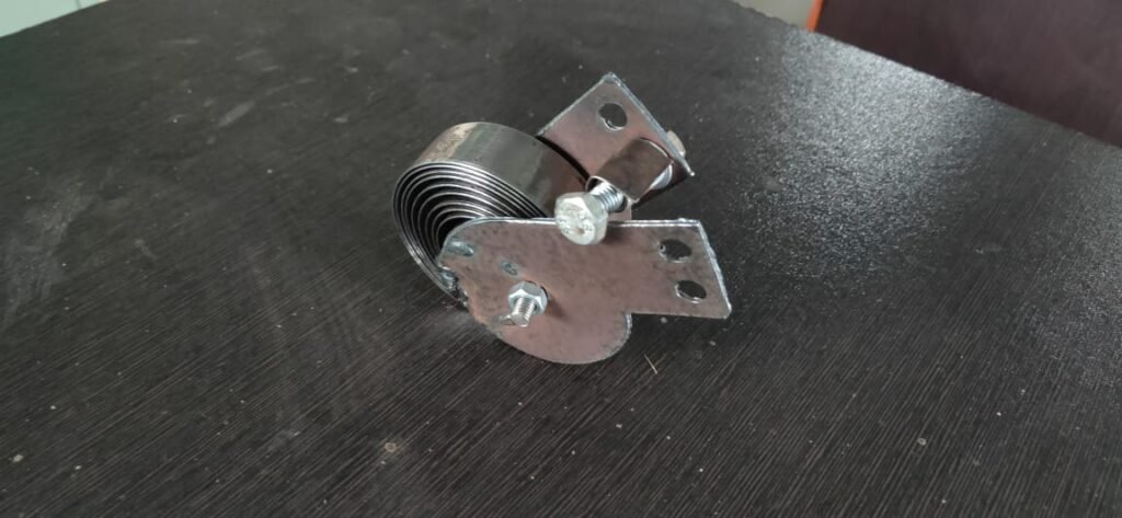
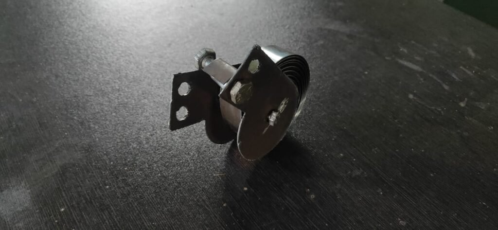
Here we finished the torque generation box, this basically stores the energy in form of strain energy one of kind potential energy. and release it when we have to lift something with bicep muscles.
Here we can find a spiral spring sandwiched between two plates hinged together, hinge joint constrain the motion to circular only and spring applies the required force in the desired or preset direction.
Assembly of spring holding mechanism and available caliper.(29/09/2021)
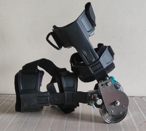
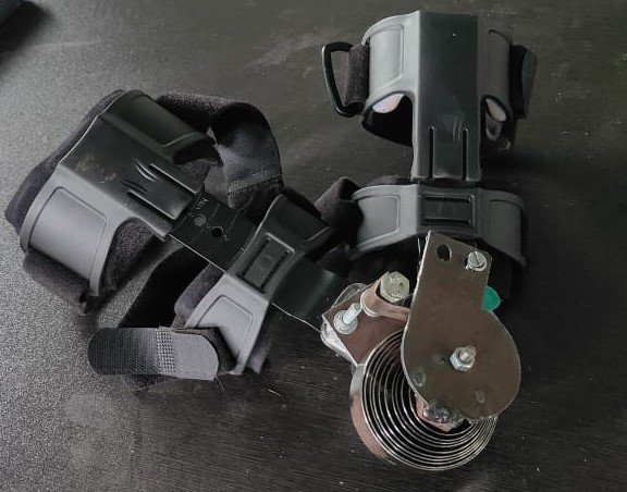
Assembly was quite tedious as drilling holes in riveted joint was quite hard thanks to worn out drilling bits, but after using new bits holed were smoothly drilled and able to fix this mechanism with caliper.
Testing the forearm exoskeleton.(30/09/2021)
This time it was quite robust and easily wearable by single person.
Added the new feature of self locking, when you want to keep your hand straight and don’t need spring assistance as shown in fig 3 you just need to straight the hand and spring will be locked at its place and will not provide support unless you bend the hand again.
Here are the photos of first experience.

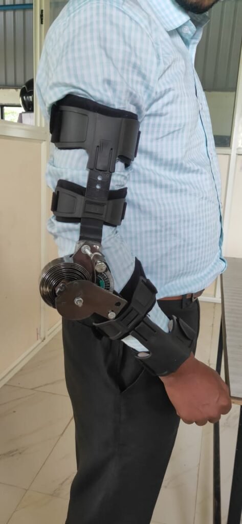
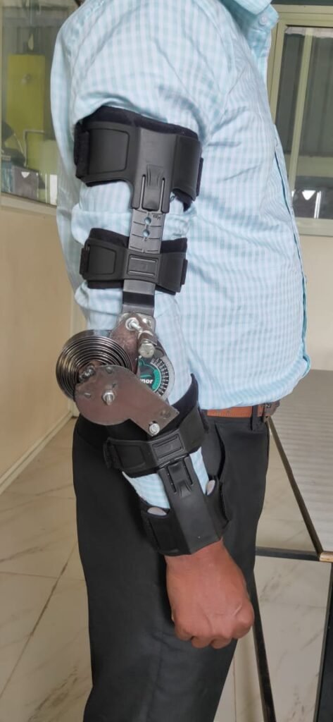
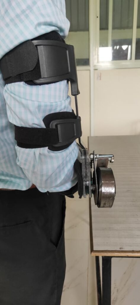
While testing it is found that spring is applying 2 kg of assistive force but after increasing pre tension the value goes high up to 3 kg of assistive force.
Shoulder Exo.(16/10/2021)
Now We are moving on shoulder part, We already have studied different shoulder exoskeletons, so currently we are working on the prototype inspiration from Comau Mate.
We selected aluminum flat plates as material for designing the caliper for shoulder because of its low weight and ease of fabrication. Here i am posting some of the photos of fabricated parts.
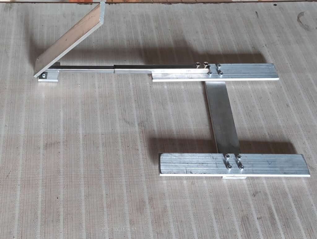
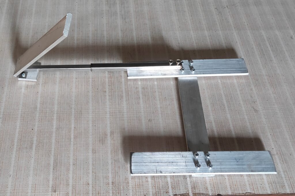
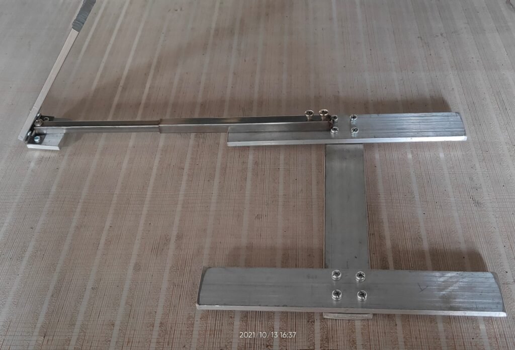
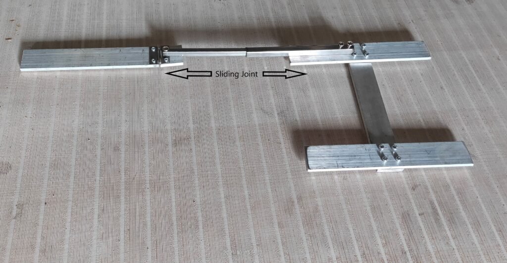
Installation of bearing. (22/10/2021)
Bearing is installed with press fit in aluminum, while aluminum is hot about 60 degrees and bearing is cold about 6-10 degrees. so after assembling and letting them to come at room temperature the joint becomes very stable.
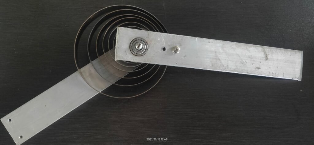
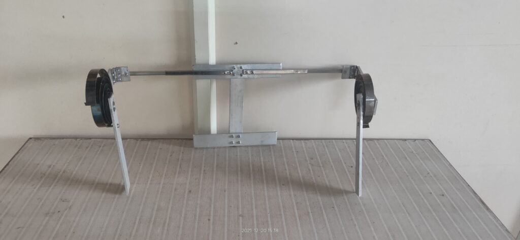
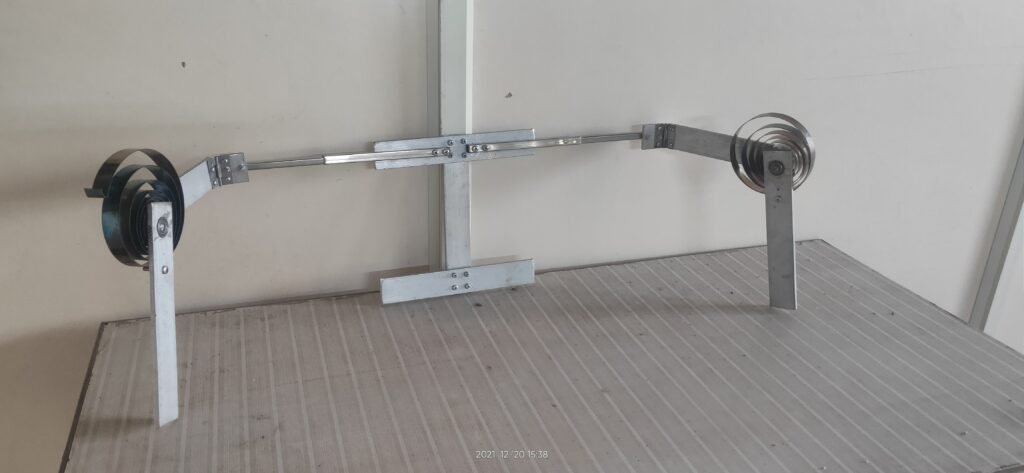
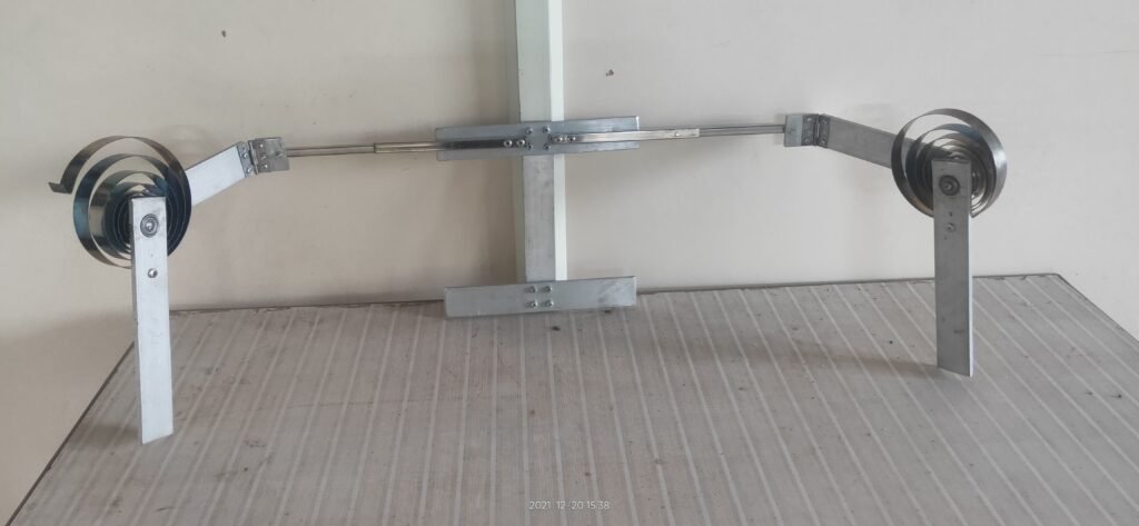
Shoulder Support Caliper getting Completed.(20/12/2021)
After a long Time the caliper of shoulder gets completed. We ware struggling to press fit the bearings into aluminum bars as it took very accurate machining and we ware struggling to get the solution. but finally we ware able to fix the bearings and complete the caliper.
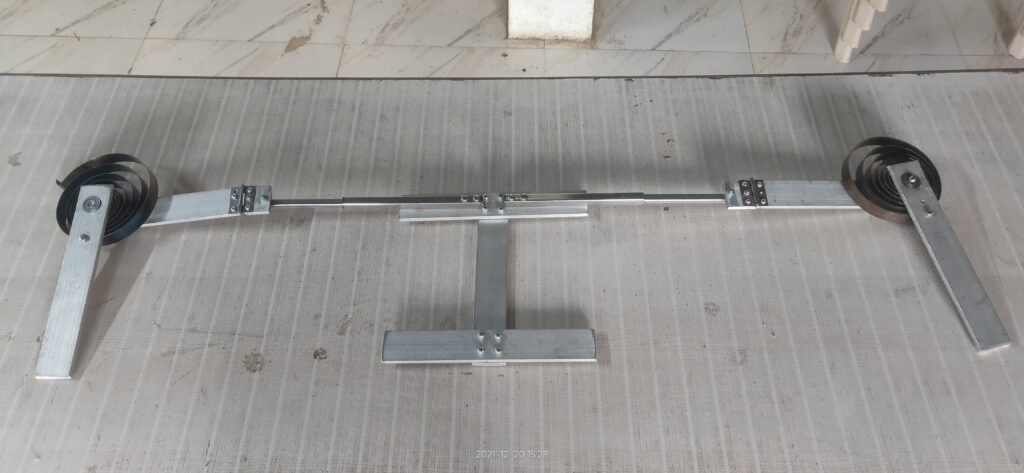
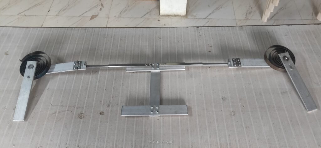
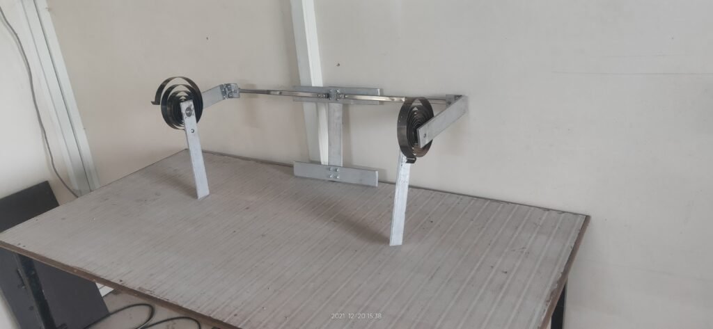
Fitting the I section frame on shoulder. (02/02/2022)
We used a fabric belt and with the help of blank rivet we stitched belt with aluminium section.
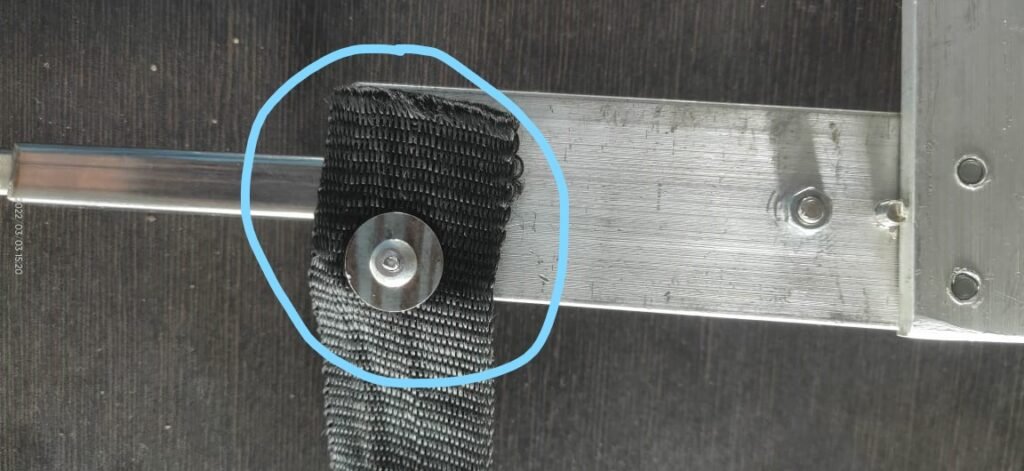
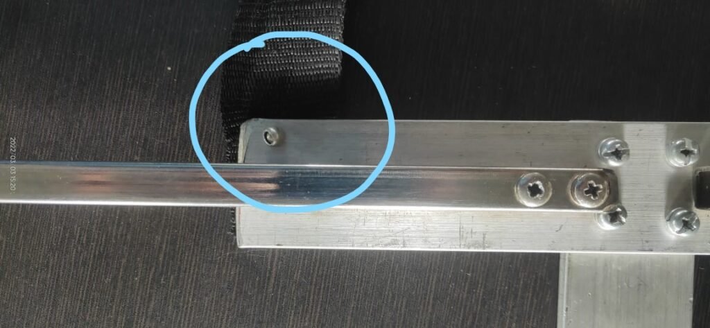
Testing the fitting of the frame on shoulder.
After some of the stitching work we were able to fix the I section of the frame on upper back of the shoulder, and it seems quite good fitting tried with different persons but it does fit to all the sizes.
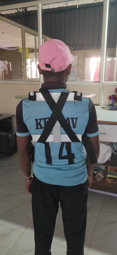
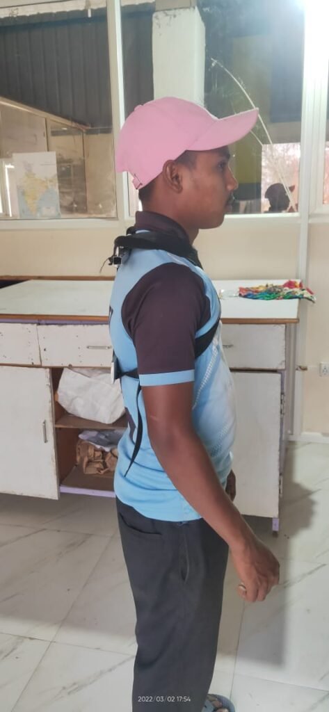
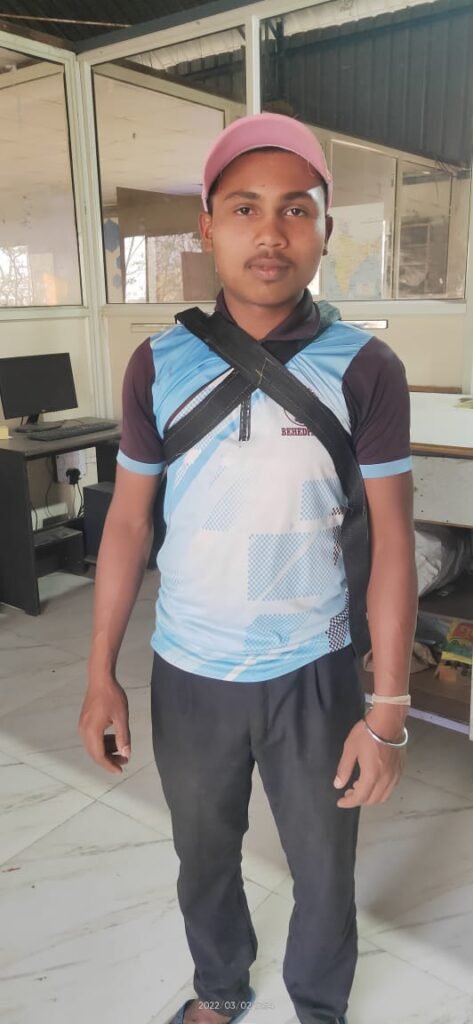
So now we are ready to connect the hinge joints with our main frame.
After connecting the hinges. (03/02/2022)
We found that the link which connects bicep are not enough close with bicep so we requires to shorten the lengths of some of the links and then we could try to connect the bicep with the link.
- A screw from aluminium rod directly touching the shoulder which was pocking.
- The bicep link is too far from the bicep so it would be difficult to connect with bicep
- Otherwise fitting of the shoulder module was acceptable.
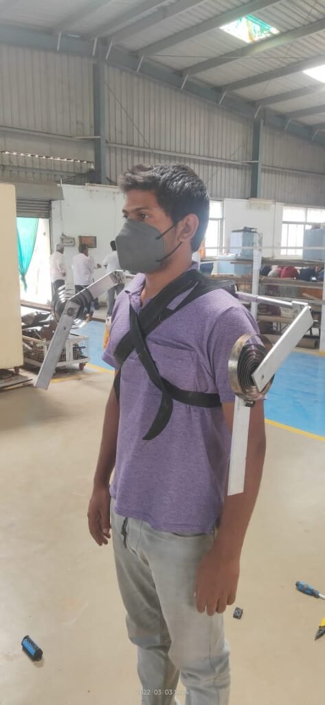
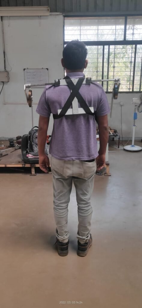
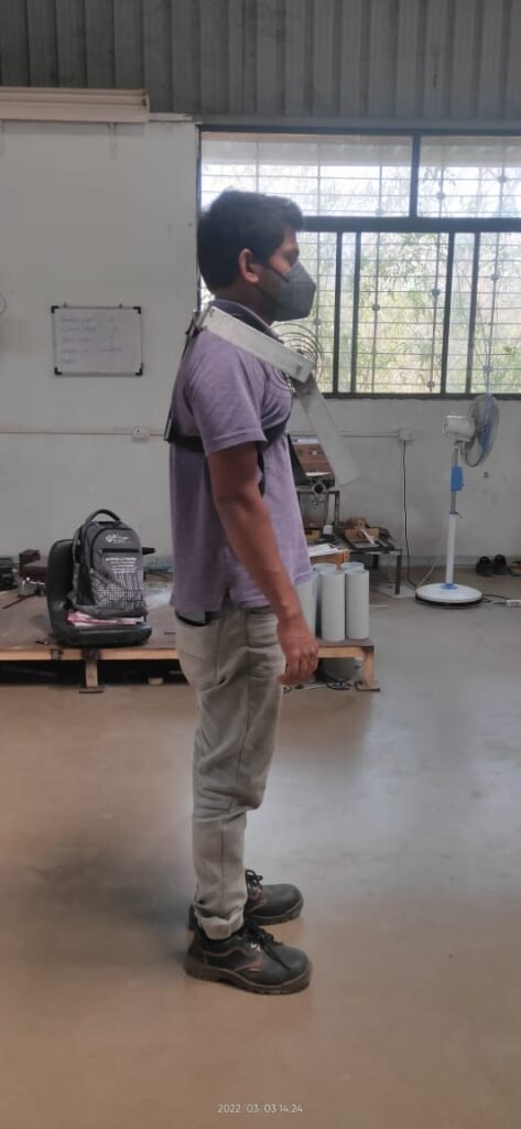
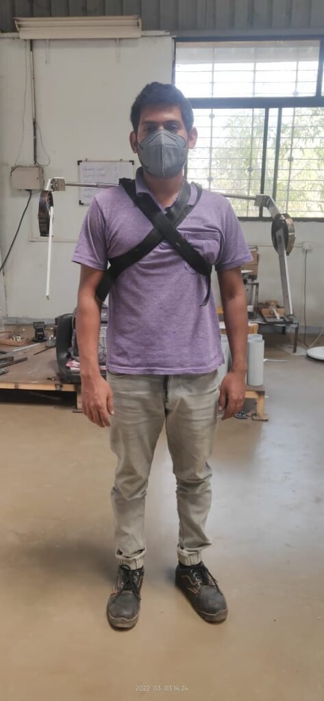
So we decided to shorten the lengths of square tube which is directly in contact with shoulder.
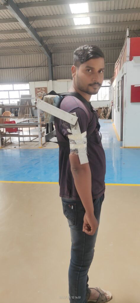
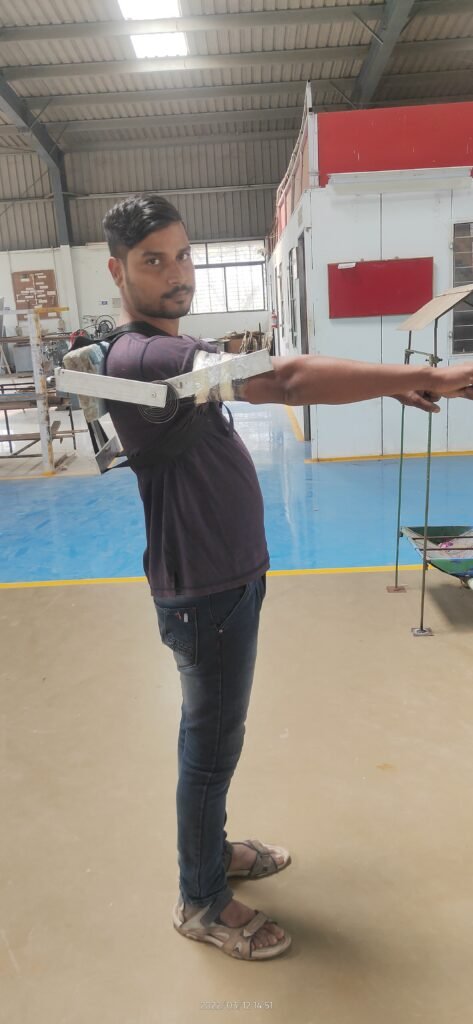
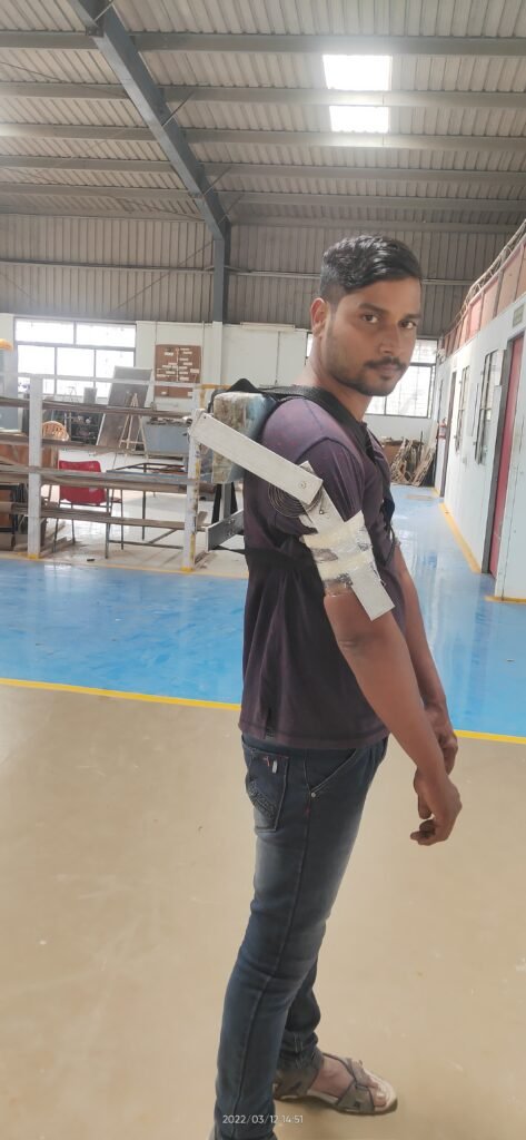
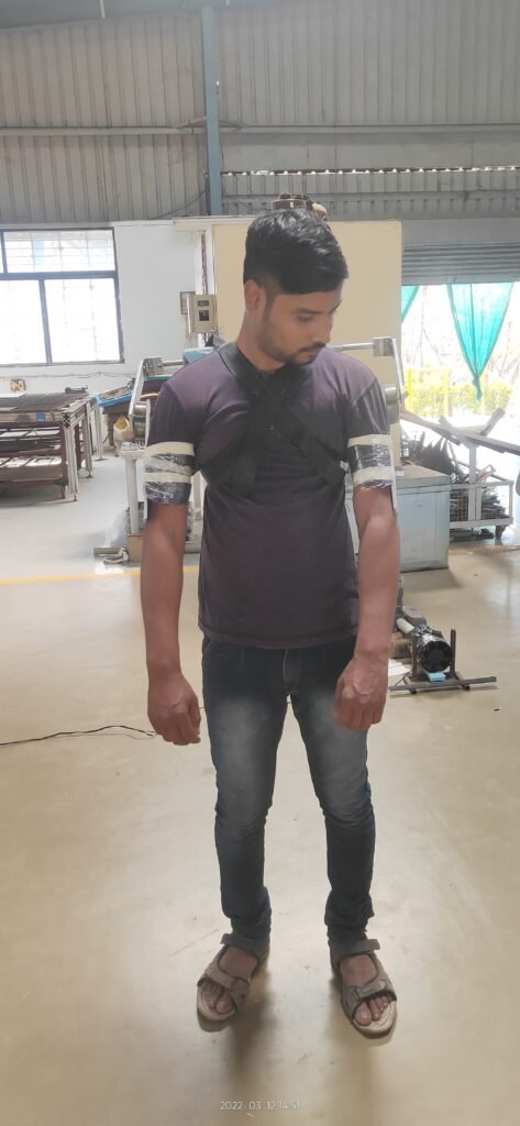
Modifications done. (12/03/2022)
- Reduced the length of square tube which 3 inches.
- Added the foam cover, so now the screw from aluminium plate is not pocking.
- System is giving the supports as expected but restricting some of the motion because the slider joint at shoulder is not performing well.
Testing with shoulder support. (04/04/2022)
After making shoulder support from PVC Pipe and connected it with link from exoskeleton it was working and producing the required force and movement but somewhat restricting shoulder motion.
Things to do.
- We used square tubes inside one another to prepare a slider but it failed because of bending movement of smaller square tube inside bigger produces more amount of friction and restricts the motion, so we will need to add some good slider.
- need to use good quality hinges, as the available are tends to bend.
- Spring which retract the shoulder needs to be changed.
- Need to add a slider joint at bicep support or shoulder support but with previous experience we will be going with bicep slider.
Installation of new hinges. (07/06/2022)
- Due to bad hinges they are getting deformed soon, so its needed to change them with good quality one.
- So they are replaced by good quality one.
Designing and assembling slider for required DOF .
- 3D model of slider is made and 3D printed.
- Testing of 1st slider model was completed.

