Problem 1: Non-Uniform Water Distribution in Pads

Temperatures in the Polyhouse reach extreme values during summer months, which is unsustainable for crop growth. A fan pad system helps in cooling the polyhouse. The pads are wet with the help of water supply pipeline and the fans help pull this moisture laden air towards the other end of the structure and reduce the temperature.
Pads are made of cellulose material. The pad dimensions are 24m length, 0.1m width and 1.45 m height. The pads are fixed at a height of 0.76m from the ground. The water holding capacity of the pads is 2.19 kg/kg.
A 24m long pipe system of diameter 1 inch is placed over the pads, the total pipe volume is 0.01 . The pipe system consists four 10ft long pipes joined with the help of unions. These pipes contain of multiple holes of diameter 4 mm drilled at irregular intervals. Water is supplied with the help of a 1HP pump and the inlet flow rate of 51.5 L/min. Inlet is at a height of 2.35 m from the ground.

Observations:

This indicates the severity of the issue i.e. around 40% of the pads remain dry. This incomplete wetting of the pads lead to reduced efficiency in cooling the entire greenhouse.

The above figure illustrates the Momentum-Friction Reciprocity flow regime i.e. at some regions momentum plays a dominant role and at others friction is dominant in other regions. A momentum dominant regime produces maximum flow rate through orifices at the end, whereas a friction dominant regime has maximum flow at the beginning and discharge reduces further along the pipe length. The following graph indicates the similarity observed to the Momentum-Friction Reciprocity Flow Regimes.

Volumetric Flow Rates through Holes:
The table below indicates the exiting volumetric flow rate and velocities through holes, when they are facing down. The water stream exiting the holes was collected in beakers and the total volume of water collected in the beakers was measured in a measuring cylinder.
Velocity = Vol. Flow Rate/ Area of Hole
| Hole No. | Vol. Flow Rate | Velocity |
| (from inlet) | (mL/sec) | (m/s) |
| 1 | 2.6 | 0.2 |
| 15 | 2.5 | 0.2 |
| 30 | 1.8 | 0.1 |
| 45 | 1.8 | 0.1 |
| 60 | 2 | 0.1 |
| 75 | 2.6 | 0.2 |
| 90 | 4.6 | 0.4 |
| 111 | 2.3 | 0.2 |
| 123 | 2.7 | 0.2 |
| 136 | 1.8 | 0.1 |
| 151 | 1.5 | 0.1 |
| 171 | 2.5 | 0.2 |
| 189 | 3.8 | 0.3 |
| 201 | 3.3 | 0.2 |
| 211 | 3 | 0.2 |
| 229 | 3.1 | 0.2 |
| 244 | 3.3 | 0.2 |
| 258 | 4.3 | 0.3 |
| 269 | 4.2 | 0.3 |
| 276 | 3.3 | 0.2 |
| 295 | 4.3 | 0.3 |
| 305 | 3.9 | 0.3 |
| 315 | 1.8 | 0.1 |
| 330 | 2.7 | 0.2 |
Possible Changes Discussed for Better Water Distribution:
- Varying the diameters of the holes
- Using a pipe of larger diameter
- Placing the pump at the centre of the pipeline
- Reversing the pipe to ensure holes are at the top and placing a deflector plate for uniform distribution.
Study of Distributors:
Distributor systems are placed as Distillation Column Internals, as has beeen detailed in the Sulzer Techinical Documents, for sufficient liquid-vapour contact in packed columns. The following Distributors develped by Sulzer were helpful for designing water distributor system for this Fan-Pad System. Following are the Distributors referred:
- Channel-type distributor with bottom holes VKG: A main channel is supplemented by side channels containing holes at bottom for liquid outlets. This system is not recommended for low liquid loads containing suspended solids.
- Channel-type distributor with lateral tubes VKR: This system is similar to previous one, however it reduces the susceptibility of the sediments to plug the holes. The liquid now falls out from the lateral tubes onto the packings.
- Slotted distributor VES: This distributor system is similar to the one prescribed by Munters. It recommends the use of deflector plates to distribute the liquid by use of open channels for liquids containing catalyst residues (here, high sediment load).
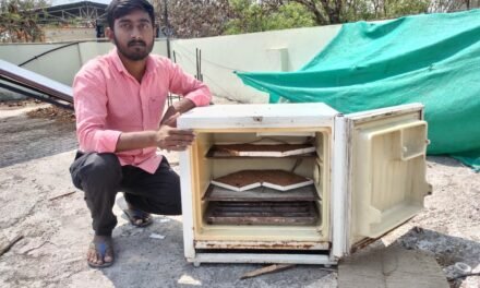
Design of Deflector Plates:
- Pipes of diameter 75 mm were cut into half, these pipes will act as the deflector plate.
- The cut pipes were fixed on to the holders using nuts and bolts.
- This setup was than placed on top of the pad wall.


Resolving Issues with Holes:
- Cleaning the burrs: Potential burrs formed due to improper drilling of holes were cleared by means of using a bent hot wire to melt the potential burrs. However, this is not a fool proof solution, as the wire has a planar spread whereas the burrs are not completely in this plane.
- Drilling of larger holes for higher discharge output.
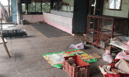
Avoiding Overflows:
Pads obstruct flow of water through the bottom gutter. The pads cover the drain, leading to excess water falling out of gutter. This can be prevented by cutting out the pad section over the oulets (as shown in the figure below).

Choice of Pump:
| Pump Used | Flow Rate (L/min) |
| 1 HP Submersible Sludge Pump | 51 |
| 1 HP Submersible Openwell Pump | 124 |
Results:
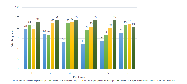
| Case | Avg. Wet Length % |
| Holes Down- Sludge Pump-Lateral Inlet | 62 |
| Holes Up- Sludge Pump-Central Inlet | 78 |
| Holes Up- Openwell Pump-Central Inlet | 85 |
| Holes Up- Openwell Pump with Hole Corrections- Central Inlet | 92 |
References:
- 3D CFD simulation of turbulent flow distribution and pressure drop in a dividing manifold system using Openfoam, N. Minocha, J.B. Joshi
- https://edis.ifas.ufl.edu/pdffiles/AE/AE06900.pdf
- https://www.sulzer.com/-/media/files/products/separation-technology/distillation-and-absorption/brochures/internals_for_packed_columns.ashx?la=en
- https://www.munters.com/en/munters/products/coolers–humidifiers/munters-plastic-gutter-mpg-b69401e9/
Problem 2: Non-Uniformity Studies of Air, Temperature and Humidity Distribution in Polyhouse

The Polyhouse is a typical twin-span/twin tunnel greenhouse used to grow various fruit and vegetable crops. The dimensions are as follows: 24 m length, 17.8 m width and 3.18 m height. It has a door of dimensions 1.83 m length, 2.06 m width and 2.3 m height. The cellulose pads are fixed along one side, and the two fans are fixed on the opposite wall.

Two fans are fixed on the wall opposite to the wall containing pads. Each fan contains six blades and the tip-to-tip diameter is around 1m. Each fan rotates with the help of a 1.5kW motor. Each fan is placed in a frame of dimensions: 1.4m x 1.4m x 0.4m. The fan is at a height of 0.86 m from the ground. The maximum discharge and suction rates were 560 and 430 cu. m/min, as calculated with the help of an anemometer.
CAD Designs:
CAD designs required for Computational Fluid Dynamics (CFD) were made using Solidworks 2018 software.


Measuring Temperature and Humidity Non-Uniformities in the Polyhouse
Understanding the diagrams that follow,
- Temperature readings in Celsius and humidity readings at the same point are indicted in the brackets. All readings are along a straight line i.e. width of the polyhouse (approx. 17.4 m)
- The first value from the left indicates reading taken at a distance of 1.5 ft from the wet pad walls. Subsequent readings are taken at intervals of 8 ft from the previous one. The final reading of the row (rightmost) in front of the fan/ at a distance of 2 ft from the side wall (depending on the case).
- The green rows indicate readings taken before noon (10:30AM-1PM). The yellow rows indicate readings taken after noon (2-4PM).
- The upper rows indicate readings taken at a height of 2.5m from ground. The bottom rows indicate readings taken at a height of 0.8m from ground level.
- Only one fan was operational when the readings were taken.
Trial 1: Temperature Data to validate Effectiveness of Pads
Case 1: Readings taken along axis in front of fan, when the fan was operational and pads were wet

Case 2: Readings taken along axis in front of fan, when the fan was operational but pads were dry

Observation:
In Case 1, temperatures at plant height level were always below 30C, which is optimal for crop growth, when fan was operational.
Clearly, data from Case 2 highlights the need to keep the pads wet in order to maintain necessary temperature conditions
Temperatures at center of Polyhouse is higher than other regions.
Trial 2: Temperature and Humidity Data at different locations in the Polyhouse
Case 1: Readings taken along an axis right in front of the fan.

Case 2: Readings taken along an axis 4.5 ft to the left of the fan


Case 3: Readings taken along an axis midway of the polyhouse (At equal distance from both fans)

Use of ANSYS Fluent for Compuatational Fluid Dynamics (CFD) to Simulate and Analyse Distribution of Temperature, Humidity and Air Flow Non-Uniformities in the Polyhouse:

2D Simulation of Front View of Polyhouse:


ANSYS Fluent Setup:
Inlet (on LHS): Pressure Inlet (0 Gauge Pressure), Temperature:300K
Outlet (on RHS): Mass flow outlet (7.3 kg/s)
Model: Laminar and Energy
Method: SIMPLE (Semi-Implicit Method for Pressure-Linked Equations)
Wall Specifications:
Input temperatures values were determined using a thermometer
Top Wall: Consists of of the roof made of HDPE
Heat flux: 67250 W/sq.m
Thickness:0.002m
Heat Generation Rate:234750 W/cu.m
Temperature:320K
Side Walls: Consists of the HDPE sheet used as wall, excludes the pad(inlet) and fan(outlet)
Heat flux: 67250 W/sq.m
Thickness:0.002m
Heat Generation Rate:234750 W/cu.m
Temperature:320K
Ground Wall: Soil
Heat flux: 430 W/sq.m
Thickness: 0.05cm
Heat Generation Rate: 8600W/sq.m
Temperature: 300K
Simulation Results:
Velocity Contour:

Velocity Vector:

Temperature Contour: