Objective: – To design chopper for composter.
Tools & Material: – Power cutter, GI pipe, iron sheet, welding machine, paint and grinder.
Constructional classification:-
1.length of chopper=130cm
2.wt.of chopper=5kg
3.diameter of chopper=25mm
4.blade lenght=length*width=20cm*11cm
5.blade thickness=0.2mm
6.stroke length=30cm
Design of chopper:-
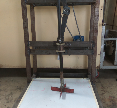
Compost chopper
Construction:-
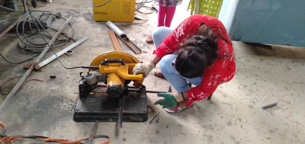
1.A hallow pipe diameter 25mm & length of chopper is 130 cm taken,cut as per diamension.
2.Blade of chopper iron sheet o.2 mm thick,cut as diamension 20cm*11cm using cutter grinder.
3.Blade was sharp with the help of blade grinder.
4.The groove of 5 cm were made on pipe as well as blade for fixing the blade into the pipe.
5.After the blade fitted into each other & pipe groove.
6.Then blade and pipe welded with welding machine.
7.Then chopper was painted.
Parts of chopper:-
Chopper assembly
- Flywheel
- Crank
- Connecting rod
- Chopper
- Motor
2. Vessel
3. Supporting system
All the above parts were designed as per dimensions given in table below.
| Sr. no. | Parts | Specifications |
| 1. | Flywheel | Diameter = 30cm |
| 2. | Crank | Length = 15 cm Rpm=20 Width=38.1mm |
| 3. | Connecting rod | Length = 23.84 cm |
| 4. | Motor | Rpm=60 |
| 5. | Vessel | Volume = 0.0266 m3 i.e. 26 lit |
| 6. | Supporting system |
Material selection:-
Motor selection:-
As the main purpose of development of chopper is to reduce the man power. Power requirement of chopper was 47.12 Watts and calculated torque was 22.50 Nm.
Connecting rod:-
Length of connecting rod was calculated as 23.84 cm. Therefore mild steel plate of width 38.1 mm and thickness 5 mm was selected. joining these bearing 6301 (inner dia = 12 mm, Outer dia. = 37 mm) was selected.
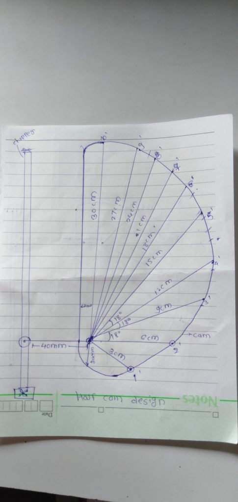
Now,i replaced connecting rod to half cam.
Problem defination:-
Connecting rod does not get affected as waste does not get chopped and then it can not be used as a fertilizer. So half the cam is going to be used.
Cam design :-

Cam profile
Mechanism of cam:-
Rough diagram of half cam:-
changes in chopper:-
1.firstly connecting rod replace by half cam.
2.Then supporting system & bearing system change by another place.
a)firstly two metel plate cut as per diamension.
b) four drill I made on metal plate with the help of drilling machine.
3. Then supporting system welded with a welding machine,Also bearing system welded with welding machine.
4.Motor and crank is a chain drive that has to be reduced, because the changing of the bearing system has changed, so the chain link will be reduced.


