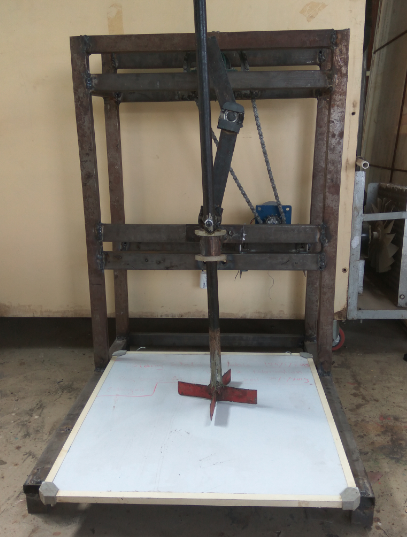
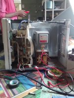
The developed mechanized wet waste chopper mainly consists of chopper assembly, vessel, and support structure. The components of chopper assembly, vessel and drives were designed theoretically. The remaining components structure and guide were developed. The methodology for development and fabrication is described as follows. Development of chopper was based on following design considerations.
1) To chop a wet waste to small size particles.
2) To develop low cost waste chopper.
3) To chop 5 kg waste per batch.
The methodology for development of chopper is as follows.
1) Support structure
Main purpose of structure of support structure is to give support and stability to chopper. All parts of the whole system was connected to support structure.
Total dimensions were kept as height of 100 cm and width was kept 70 cm by considering the chopper assembly as explained before/above. First two frames of size 100 x 70 cm was made and then joined together with 25 cm rectangular tube. Then to give extended support to structure a frame of 70 cm x 50 cm was connected to bottom of structure where the vessel can be kept.
At the top L angle sections of 22.5 cm length were welded to fix pedestal bearings P204 for shaft of 20 cm diameter.
At the middle section of structure i.e. 48 cm from top another 62 cm length m. s. rectangular tube was welded for fixing the guide to restrict the horizontal movement of chopper. The guide was made from m s pipe of diameter 46.76 mm and length 8.5 cm. The bushes were made from polypropylene roller. These bushes were turned and bored with desired dimensions on lathe machine.
2) Chopper assembly

Chopper assembly consists of crank, connecting rod and chopper.
i. Crank
Crank was made with mild steel plate of width 38.1 mm and 5 mm thickness. The length of crank was 15 cm. One end of the crank is fixed to shaft and another end is connected to the connecting rod.
ii. Connecting rod / link
Connecting link was made with mild steel plate of mm thickness. The length of connecting link was derived 23.84 cm. At the both ends of this plate the pipe of diameter 55 mm and length 1.7 cm was welded in which the bearings 6301 were inserted. The bushes for these bearings were also made with PP roller.
In these bearings the bolts/studs M12 were inserted to join one end to crank and another end to chopper.
iii. Chopper
Chopper was made with mild steel pipe of 25 mm diameter. The length of chopper was kept 50 cm. The blades of chopper was made with mild steel plate of width 38.1 mm and 5 mm thickness. The size of blades was 20 x 4 cm.
Chopper was drilled at 45 cm height and then it was connected to connecting link with help of heavy duty bolts M12.
3) Motor mounting and drives
Motor was mounted in the middle of structure i.e. 45 cm from top. The movable stand made from L angles on which the motor was mounted. Stand was movable so that to fix the alignment.
To fix chain drive, the bigger sprocket was fixed on the shaft and the smaller sprocket was fixed on motor shaft. The chain was mounted on these both sprockets and aligned.


