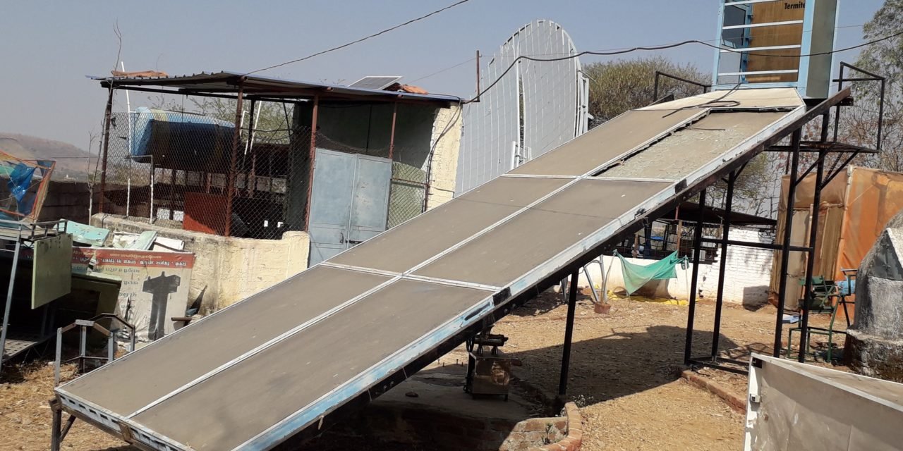
The existing convection dryer at Vigyan ashram has been damaged and also needs some modifications to improve its efficiency and accessibility.
Objective:
- To replace the broken glass of the air heater of the dryer,
- To seal the gaps between consecutive air heaters,
- To insulate the back of the air tunnel.
Problems with the current dryer:
The convection dryer has following issues,
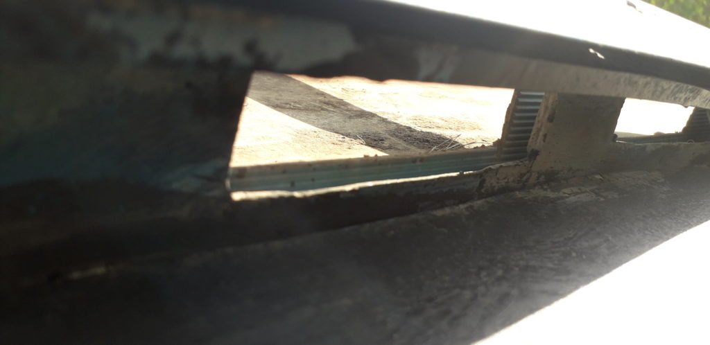
- One out of six glasses used for air heater is broken,
- The paint on the absorbing surface has faded,
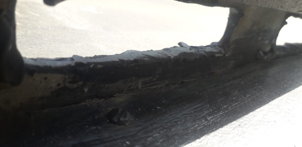
- The outlet of one heating box and the inlet of the next are not insulated. The space between them causes heat loss,
- The insulation foam is not properly fixed to the back of the air heater, hence some heat is lost through the insulating foam as well,
- The drying chamber has also been damaged and the glass wall at its front has been broken.
- The drying chamber is not easily accessible.
Repairing and Insulation of the dryer.
Cleaning and disassembly of the dryer:
- The first task in this project was to collect pieces of broken glass and disassemble the air heater as well as the drying chamber.
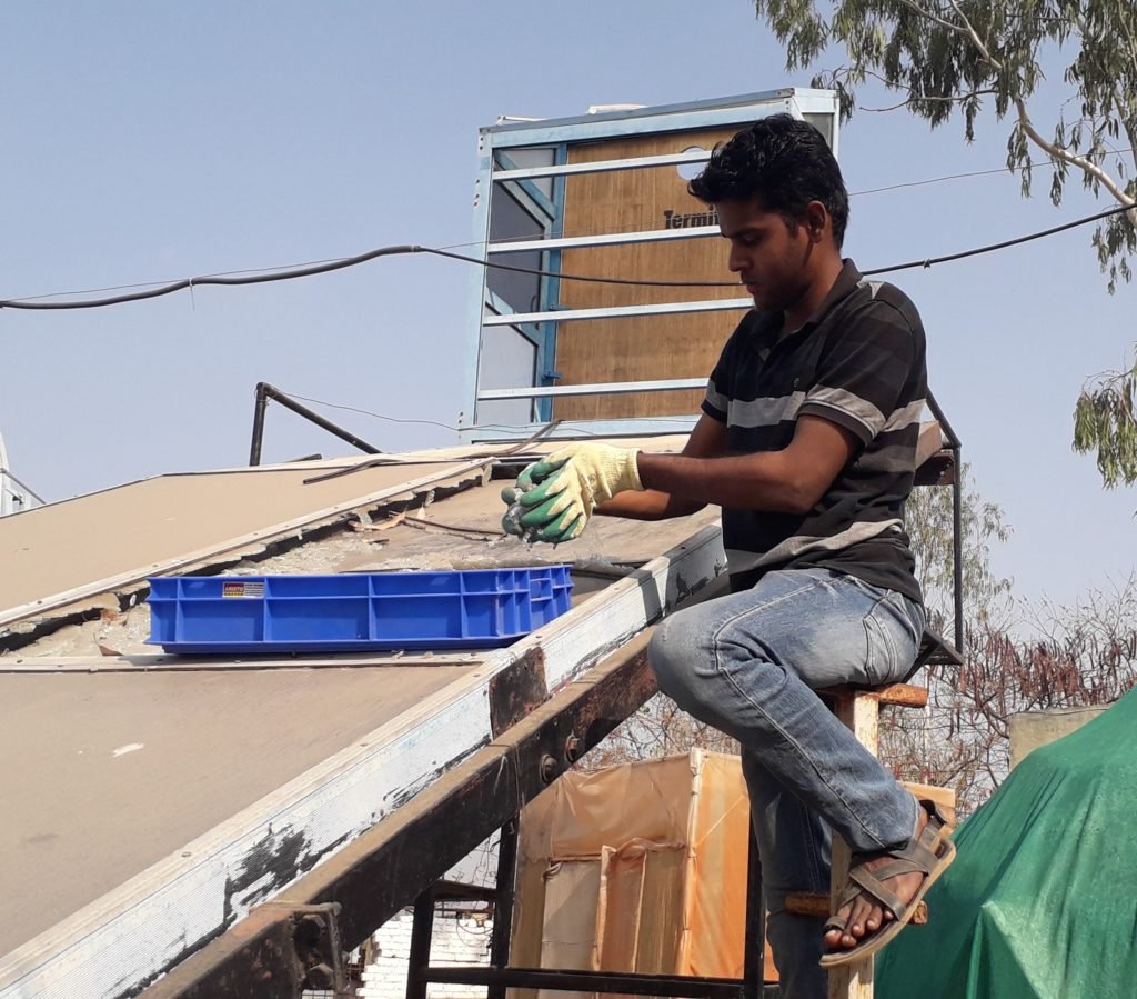
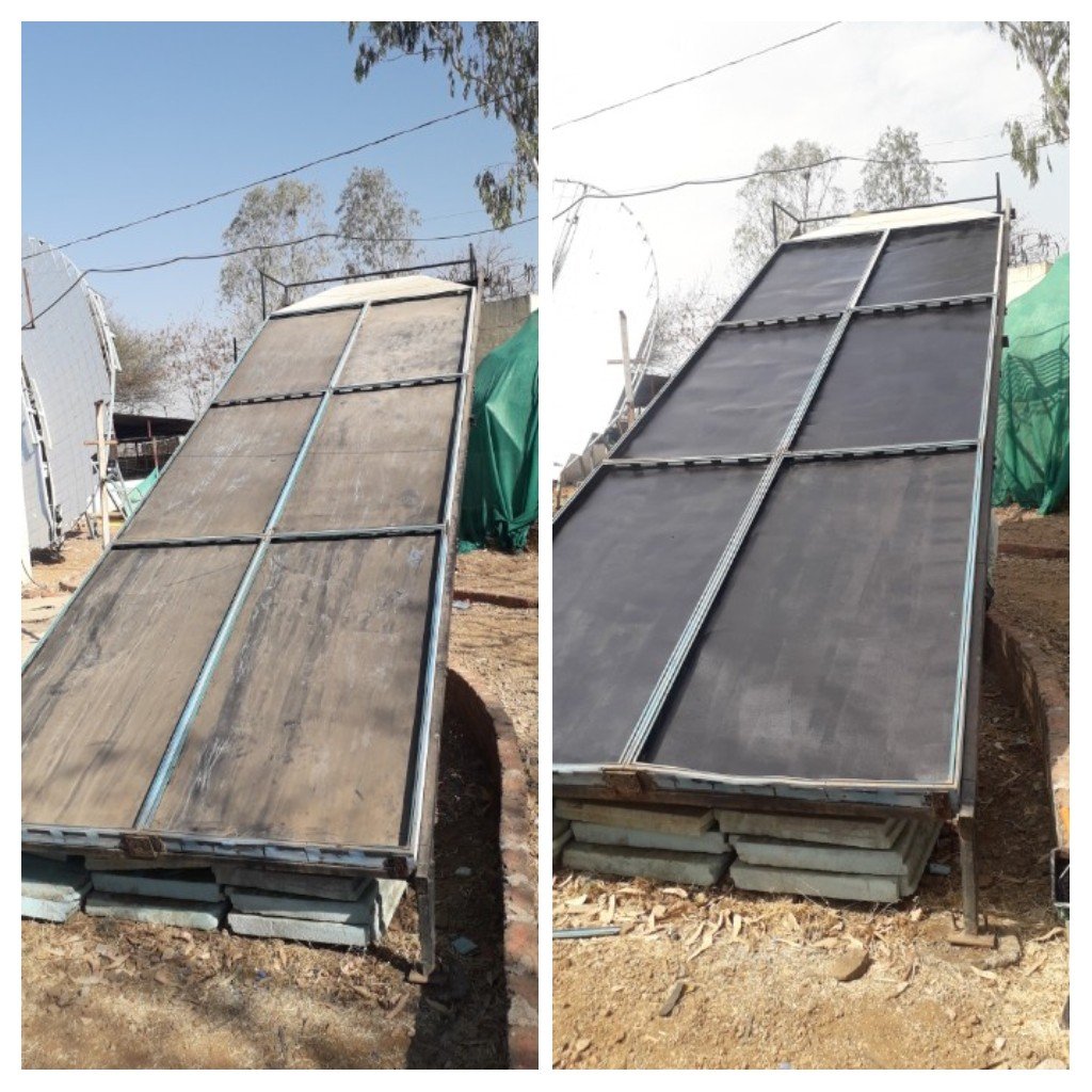
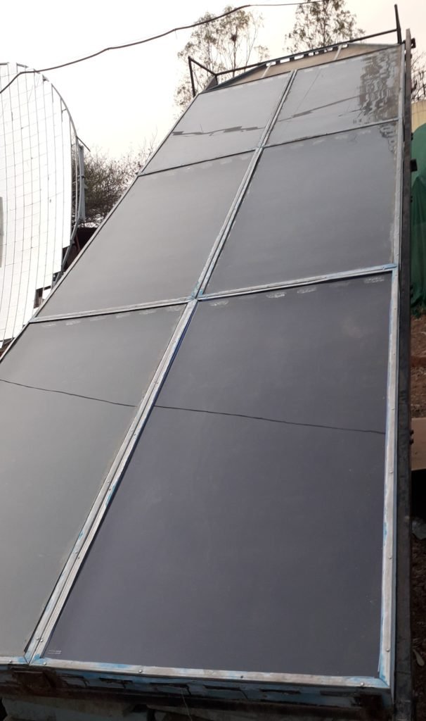
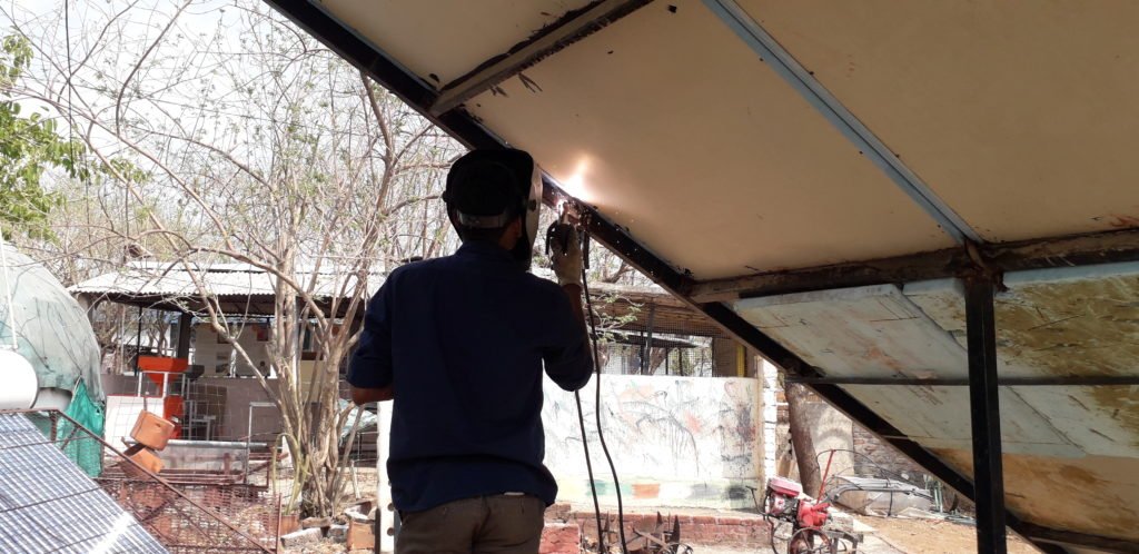
Painting the surface of air heater:
- The temperature of the absorbing surface of the solar convection dryer could reach around 100-degree celsius hence, the absorbing surface should be painted with a heat resistant paint.
- To paint the absorbing surface Shiv shakti HR BLACK 600 DEGREE paint has been used. This paint can retain its properties up to 600 degrees of temperature.
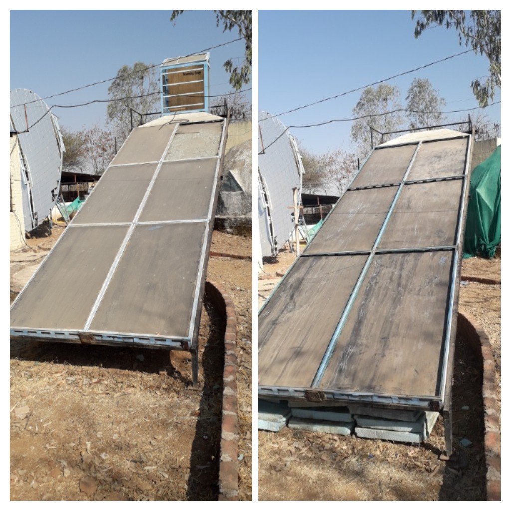
- The surface of air heater was cleaned by a wet mop first, then with the help of sandpaper the previous layer of paint was removed and the surface of the heater was made rougher so that new paint can stick to it properly.
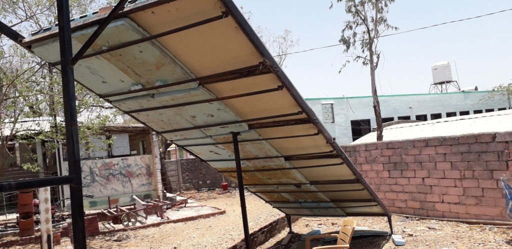
Sealing the gap between air heaters:
- In convection dryer, the air is heated in two different columns of air with 3 air heaters in each column.
- Air enters the lowest air heater, gets heated and as its density decreases with temperature it progressively moves upwards towards the second and then towards the third air heater
- Finally, hot air from 2 columns is mixed and supplied to the drying chamber.
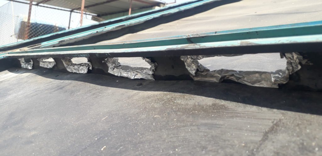
- The problem with this arrangement was that the consecutive air heaters in columns were not sealed properly. There were gaps ranging from 2 mm to 2 cm between them.
- It means that all the air heated in the first column didn’t enter the second column completely and some amount of it was lost through these gaps. Hence it was necessary to seal these gaps to increase the efficiency of convection dryer.
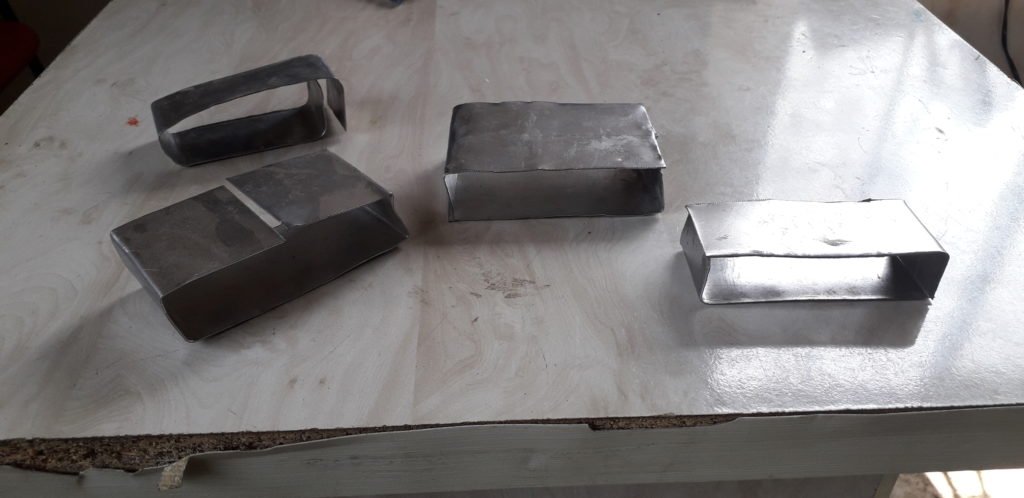
To avoid losses different types of ducts were tried but the idea was dropped since these ducts couldn’t seal the gaps effectively.
Later after discussion with a colleague I used aluminium foil to seal the gaps.
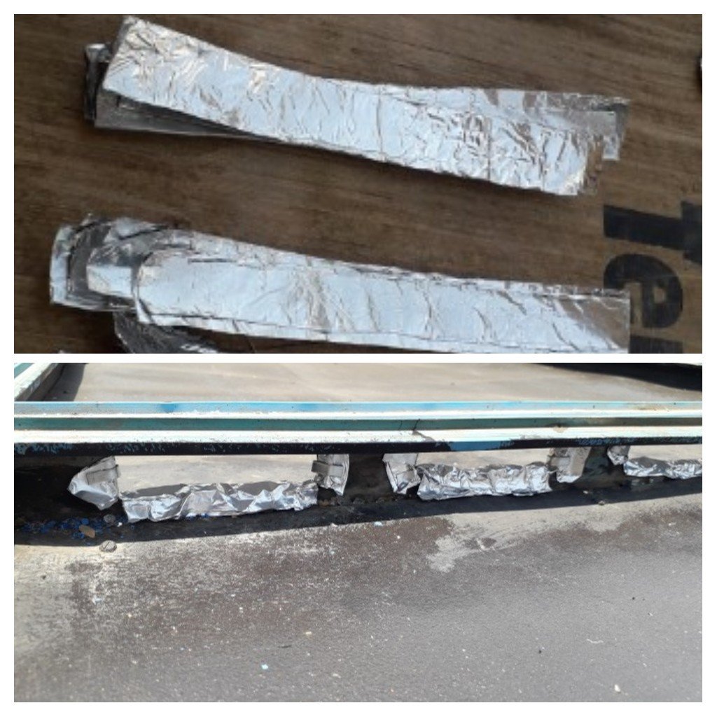
Although aluminium foil sealed the gaps effectively there was a possibility of tearing of aluminium foil from outside. Dixit sir suggested to use M seal or other similar alternatives as it would seal the gaps permanently.
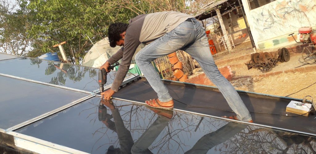
Installation of glass:
Once the gaps between air heaters were sealed it was time to install the glasses. Since the glasses were lying in open some dust had accumulated on their surfaces. The glass surfaces were cleaned using water and a wiper and were later installed.
Installation of insulation foam:
Insulation was provided to the air heaters using XPS foam which was supported by binding wire. As the binding wire had undergone permanent deformation due to the weight of the foam it was not tightly in contact with the back of heat absorbing surface and was hanging loose,
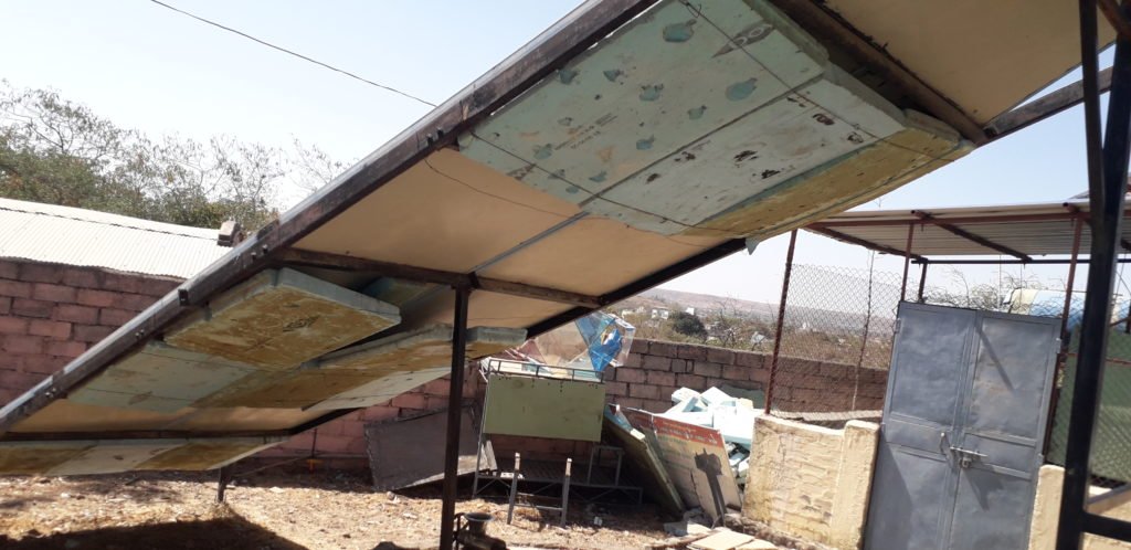
Hence the binding wire was replaced by L angle (22mm*22mm*3mm).
Initially, the back of the absorber surface was divided into 6 parts and 1 L angle at the middle of each part was installed. After installation, it was found that 1 L angle is not enough to support the insulation foam hence in each part 2 L angles, 1 at the upper and 1 at the lower part was installed.
