Introduction
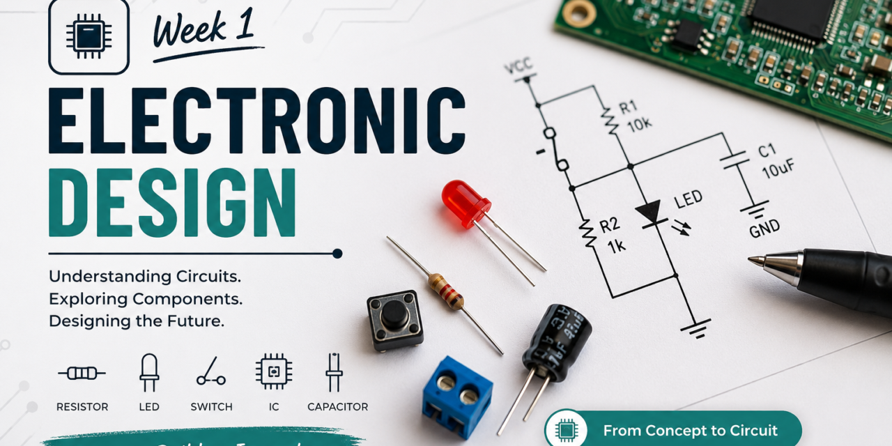
As part of the Fab Opportunity Academy, my first week’s assignment focused on Electronic Design. The objective of this module was to help me understand the fundamentals of electronic circuits, identify commonly used electronic components, and learn the process of designing electronic circuits using PCB design software.
During this week, I learned about different electronic components and their roles in a circuit. I also studied how electric current flows, how components are connected, and how a simple circuit works. In addition, I explored EDA tools.
About electronic design
What is Electronic Design?
Electronic design is the process of creating electronic circuits that perform a specific function. an electronic circuit is a path through which electric current flows to make an electronic device work.It involves selecting the right electronic components such as resistors, LEDs, capacitors, switches, sensors, and micro-controllers. Electronic circuits are used in almost every electronic device, including mobile phones, computers, TVs, robots, and home appliances.Electronic design includes both hardware and software.
Current

Electric current is the flow of electric charge through a circuit,just like water flows through a pipe from a water tank.Current is measured in Ampere (A).If too much current flows,it can damage electric components.To control the flow of current and protect the components, a resistor is used.
Voltage
Voltage is the electrical force that pushes current through a circuit, just like water pressure pushes water through a pipe from a tank. Voltage is measured in volts (V).
Resistance
Resistance is the opposition to the flow of electric current. It limits the amount of current flowing through a circuit, which helps protect electronic components. Resistance is measured in ohms (Ω), while a resistor is the electronic component used to provide resistance in a circuit.
Power
Power is the amount of electrical energy used or produced by a circuit. It depends on both voltage and current and is measured in watts (W). More power means more electrical energy is being used.
Conductor
Conductor is a material that allows electric current to flow easily through it because it has free electrons. Materials like copper, aluminium, and silver are commonly used as conductors in electrical circuits for connecting components.
Insulator
Insulator is a material that does not allow electric current to flow easily through it. It is used to protect people and electronic components from unwanted current flow. Materials like plastic, rubber, and glass are commonly used as insulators.
Ground
Ground (GND) is the common reference point in an electric circuit. It provides a return path for electric current to flow back to the power source.
Ohm’s Law
Ohm’s Law explains the relationship between voltage, current, and resistance in an electric circuit. It is written as: V = I × R, where V is voltage (volts), I is current (amperes), and R is resistance (ohms). I learned that if the voltage increases, the current also increases, while increasing the resistance reduces the current.

Electronic Components
We learned that electronic components are basic parts used to build electronic circuits and devices. Each component has a specific function and helps the circuit work properly.

1. LED

LED (Light Emitting Diode) is a type of diode that produces light when electric current flows through it. An LED has two terminals: the positive terminal (Anode) and the negative terminal (Cathode/GND). The LED allows current to flow in one direction and is commonly used for indicators and lighting applications.
2. Resistor

Resistor is an electronic component used to limit the flow of electric current in a circuit.They are commonly used in circuits for controlling voltage, limiting current, and adjusting signal levels.It helps protect other components from damage. The value of a resistor is measured in ohms (Ω).resistor usually has colored bands on its body that represent its resistance value. Different resistor values are used depending on the fdggrfgrequirement of the circuit.
For example, a 220Ω resistor allows less current to flow compared to a 100Ω resistor, helping to protect components like LEDs from damage.
- 100Ω (Ohms)
- 220Ω (Ohms)
- 1kΩ (1000Ω)
3. Switch

Switch is an electronic component used to control the flow of electric current in a circuit. It can open the circuit to stop the current flow or close the circuit to allow current to pass. Switches are used to turn devices on and off or to control different functions in electronic systems.
4. Capacitor

Capacitor is used to store electrical energy for a short time. It stores energy in an electric field and releases it when needed.It can charge and discharge energy in a circuit and Capacitors are used in electronic circuits for filtering, smoothing voltage, removing noise, and providing stable power to components.The value of a capacitor is measured in farads (F), commonly in micro-farads (µF) and nano-farads (nF).
5. Diode

Diode is an electronic component that allows electric current to flow in only one direction and blocks the flow in the opposite direction. It has two terminals: anode (+) and cathode (-). Diodes are used in circuits for protection, rectification, and controlling the direction of current flow.
6. Transistor

Transistor is used to switch or amplify electrical signals. It has three terminals—Emitter (E), Base (B), and Collector (C). A small current applied to the base controls a larger current flowing between the collector and emitter.
Sensors

We learned that a sensor is an electronic component that detects changes in its surroundings, such as light, temperature, motion, distance, or humidity, and converts them into electrical signals. These signals can be read by a micro-controller to perform different tasks. Sensors are widely used in automation, robotics, IoT, and smart electronic systems.
Electronic Components Types
1. Active Components
Active components require power to operate and can control or amplify electrical signals.
Examples:
- LED – Produces light when current flows through it.
- Sensors – Detect changes such as light, temperature, or motion.
2. Passive Components
Passive components do not generate or amplify electrical signals. They only control, store, or use electrical energy.
Examples:
- Resistor – Limits the flow of current.

We learned that electronic components are the building blocks of electronic circuits. They are classified into active components, which require power to control or amplify signals and passive components, which control or store electrical energy, and Together, these components help electronic devices perform different functions.
Types of Electronic Components Based on Mounting Type
Electronic components are classified into two types based on how they are mounted on a Printed Circuit Board (PCB).
1. Through-Hole Components (THT)
Through-hole components have long metal leads that are inserted into holes drilled in the PCB and soldered on the other side. They provide strong mechanical support and are commonly used for prototypes, educational projects.
2. Surface Mount Components (SMD)
Surface-mount components are mounted directly onto the surface of the PCB without drilling holes. They are smaller, lighter, and allow more components to fit on a PCB, making them ideal for modern electronic devices.
Examples:
- SMD Capacitors
- SMD LEDs

Individual assignment
In my individual assignment, I worked on different basic electronics activities, including making paper circuits, performing soldering on a zero PCB (perfboard), and programming an IR sensor using Arduino.
Making of Paper Circuit
I created paper circuits using copper tape, LEDs, resistors, and a coin cell battery. I created three types of circuits: a flap tap switch circuit, a series circuit, and a parallel circuit. The flap switch works by opening and closing the connection to turn the LED on and off. In the series circuit, the components are connected in one path, so the same current flows through all parts. In the parallel circuit, the components have separate paths, allowing each LED to work independently. This project helped me understand how electricity flows and how different circuits work.


Soldering on Zero Board
I completed line soldering on a zero PCB (perfboard).


IR Sensor
I connected an IR sensor with an Arduino and programmed it using Arduino IDE to detect nearby objects. When an object is detected, the system activates and blinks an LED as an indication. This project helped me understand sensor interfacing and Arduino programming


Group assignment
As part of the group assignment, we built a simple electronic circuit using a Seed studio XIAO ESP32 C3, a breadboard, an LED, jumper wire and a resistor. We connected the components correctly on the breadboard and uploaded a basic program to control the LED.


After building the circuit, we used a digital multi-meter to measure the voltage and current in the circuit. This activity helped us to understand how to build a basic circuit, verify electrical connections, and use a multi-meter to test and troubleshoot electronic circuits.


Multimeter
We learned that a multi-meter is an electronic measuring instrument used to test and troubleshoot electrical and electronic circuits. We used it to measure voltage (V), current (A), and resistance (Ω).
Common functions of a multimeter:
- Voltage (V) – Measures electrical voltage.
- Current (A) – Measures the flow of electric current.
- Resistance (Ω) – Measures the resistance of a component.
- Continuity Test – Checks whether two points are electrically connected.
- Diode Test – Tests whether a diode is working properly.
Electronic Design Automation (EDA)
EDA (Electronic Design Automation) is the use of software to design, test, and verify electronic circuits and PCBs before they are manufactured.
Why Tinkercad
We first use Tinkercad to design, simulate, and test electronic circuits online. It helps us learn electronics, find mistakes early, and build better circuits before using real components.

Individual assignment (Circuit simulation in Tinkercad)
I designed and simulated several basic electronic circuits in Tinkercad to understand fundamental electronics concepts. These included a simple coin cell, LED, and resistor circuit, as well as Arduino-based circuits using a push button, slide switch, and parallel circuit. These simulations helped me to understand circuit operation, test designs, and identify errors.


Kicad & Addition of Fab Library
About kicad
KiCad is a free and open-source Electronic Design Automation (EDA)software used to design electronic circuits and printed circuit boards (PCBs).We use KiCad to draw circuit schematics, design PCB layouts, manage component libraries, and generate manufacturing files for PCB fabrication. It also includes tools to check for design errors, helping us create reliable and accurate PCB designs
Installation of KiCad
Step 1 – First, I searched for KiCad for Windows on Google.

Step 2– I opened the official KiCad website then I went to the download section and downloaded the latest KiCad installer on my computer.


Step 3– Then I installed the Fab Library to access additional symbols and footprints required for PCB designing. I downloaded the library files, added them to KiCad through the library manager, and verified that the new symbols and footprints were available for use.I downloaded the library in Schematic & PCB editor.


Creating a Circuit Of Seed studio XIAO ESP32-C3 in KiCad
Step 1– I created a simple XIAO ESP32-C3 LED blink circuit in KiCad. First, I opened the Place Symbol tool and selected the required components, such as the ESP32-C3, LED, resistor, and power symbols(PWR flag,Pwr GND). Then, I placed the components in the schematic and prepared them for circuit connections.


Step 2– Then, I ran the Electrical Rules Checker (ERC) to identify and fix any errors in the schematic before proceeding to the PCB design.

Step 3– After that I updated the PCB in the PCB Editor. This transferred the schematic components to the PCB layout, where I arranged them for board design.


Step 4-Then I drew the Route Tracks to connect the components according to the circuit design. This completed the PCB routing for the circuit.I set the track width to 0.4 mm in the PCB Editor.


Step 5– I drew a rectangle around the PCB and set it as the Edge.Cuts layer to define the outline and size of the circuit board.


Step 6- Finally, I ran the Design Rules Checker (DRC) in the PCB Editor to check for layout errors. I fixed any issues found and confirmed that the PCB design was ready for manufacturing.

3D View of PCB

Individual assignment
My First PCB-My first PCB was a simple circuit that included an LED, a resistor, and a 1×2 male header pin. I designed the schematic in KiCad, connected the components, updated the PCB layout, routed the tracks, and verified the design using ERC and DRC checks. This project helped me learn the basic steps of PCB design.