Introduction
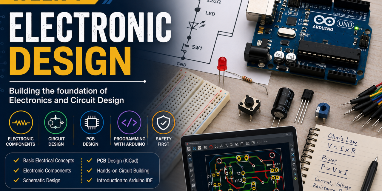
This week focused on understanding basic electronics and the tools needed for electronic development. I looked into components like resistors, LEDs, capacitors, switches, and connectors, learning how each part works in a circuit. I also learned about key concepts such as current flow, voltage, and how different components interact in a circuit.
I learned to use Electronic Design Automation (EDA) software for making circuit schematics and PCB layouts, which helped me see how circuits are designed before they are made. I also used the Arduino IDE to write, upload, and test simple programs for electronic components. Overall, this week gave me a solid foundation in electronics, blending theory with hands-on experience in circuit design and programming.
Basic Electrical Concepts
What is Current –
Electric current is the movement of electric charge in a wire or circuit. It indicates how much electricity is traveling between points. Current flows when there is a complete path known as a circuit. It is represented by the symbol I and measured in Amperes (A). Resistors control the current flow and protect electronic parts.

What is Voltage –
Voltage is the force that pushes electric current through a circuit, like water pressure in a pipe. It gives the energy for electrons to move. Voltage is shown as V and measured in Volts (V). Batteries and power supplies provide voltage. Without voltage, current cannot flow in a circuit.

What is Power –
Power is the electrical energy used in a circuit, showing how fast work is done. It is symbolized by P and measured in Watts . In circuits, power depends on voltage and current and can be calculated using the formula:

What is Resistance –
Resistance is something that slows down the flow of electricity in a circuit. It helps control the amount of current flowing through components and protects them from damage. Resistance is measured in Ohms (Ω) and represented by the symbol R.

What is Ohm’s Law –
Ohm’s Law explains the relationship between voltage, current, and resistance in an electrical circuit, stating that current increases when voltage increases and decreases when resistance increases, and it can be used to calculate Voltage, Current, or Resistance when any two of these values are knownbd268
Electronics Components
Electronic components are the basic building blocks of an electronic circuit. Each component has a specific function, such as controlling current, storing energy, producing light, or connecting different parts of a circuit. Understanding these components is essential for designing and building electronic projects.
1.Resistor –
A resistor is used to limit or control the flow of electric current in a circuit. It helps protect electronic components from excessive current.

2. LED –
An LED is a semiconductor device that emits light when electric current passes through it. It is commonly used as an indicator or for lighting purposes.

3. Capacitor –
A capacitor is an electronic component that stores electrical energy temporarily and releases it when needed in a circuit.

4. Switch –
A switch is used to open or close an electrical circuit, allowing or stopping the flow of current.

5. Push Button –
A push button is a simple switch that is used to control the flow of current in a circuit. When the button is pressed, the circuit is completed and current flows; when it is released, the circuit opens and the current stops. Push buttons are commonly used for user input in electronic devices and projects.

6. Diode –
A diode is an electronic component that allows electric current to flow in only one direction and blocks it in the opposite direction. It is commonly used for rectification, circuit protection, and controlling the direction of current flow in electronic circuits.

7. Transistor –
A transistor is a semiconductor device used to switch or amplify electronic signals in a circuit. It acts as an electronic switch that can control the flow of current. Transistors are widely used in electronic devices such as computers, mobile phones, sensors, and microcontrollers.

8. Sensor –
A sensor is an electronic component that detects changes in the environment and converts them into electrical signals. Sensors can measure physical parameters such as temperature, light, motion, distance, humidity, or pressure. They are widely used in automation, robotics, IoT devices, and smart systems to collect real-world data.

9. Arduino Uno –
one of the most popular microcontroller boards based on the ATmega328P microcontroller. It is widely used for learning electronics, programming, robotics, and IoT projects. The board can read inputs from sensors and buttons, process the data, and control outputs such as LEDs, motors, and displays. Arduino Uno can be programmed using the Arduino IDE through a USB connection, making it easy for beginners and students to develop electronic projects.

10. XIAO ESP32-C3 –
The Seeed Studio XIAO ESP32-C3 is a compact and powerful microcontroller board based on the ESP32-C3 chip. It features built-in Wi-Fi and Bluetooth Low Energy (BLE) connectivity, making it ideal for IoT and wireless communication projects. Despite its small size, it provides multiple GPIO pins for connecting sensors, actuators, and other electronic components. The XIAO ESP32-C3 can be programmed using the Arduino IDE and is widely used in smart devices, automation systems, and embedded applications.

Electronic Component Types
Electronic components are classified into different categories based on their function and method of mounting on a printed circuit board (PCB). Understanding these classifications helps in selecting the appropriate components for designing, assembling, and troubleshooting electronic circuits. The most common categories include Passive Components, Active Components, Through-Hole Components (THT), and Surface Mount Devices (SMD).
1. Passive Components –
Passive components are electronic devices that do not require an external power source to operate and cannot amplify signals. They are mainly used to control, store, or dissipate electrical energy in a circuit.
Examples: Resistors, Capacitors, and Inductors.

2. Active Components –
Active components require an external power source to function and can control, amplify, or switch electrical signals. These components play an important role in processing and controlling electronic circuits.
Examples: Transistors, Diodes, Integrated Circuits (ICs), and Microcontrollers.

3. Through-Hole Components (THT) –
Through-Hole Components are electronic parts with leads that are inserted through holes drilled in a PCB and soldered on the opposite side. They provide strong mechanical connections and are commonly used in prototyping and educational projects.
Examples: Through-hole Resistors, LEDs, Capacitors, and Push Buttons.

4. Surface Mount Devices (SMD)
Surface Mount Devices (SMD) are components that are mounted directly onltw1o the surface of a PCB without using holes. They are smaller, lighter, and allow high-density circuit designs, making them widely used in modern electronic products.
Examples: SMD Resistors, SMD Capacitors, SMD LEDs, and SMD ICs.

LED Control Circuit Using Tinkercad
As part of this activity, I designed and simulated a simple LED control circuit using Tinkercad. The circuit consisted of an Arduino Uno, a breadboard, two LEDs, jumper wires, and a slide switch. The LEDs were connected to the Arduino through the breadboard, and the slide switch was used to control which LED would turn on.
The circuit was programmed so that when the slide switch was moved to the left position, the left LED turned ON, and when the switch was moved to the right position, the right LED turned ON. Through this simulation, I learned how to connect components on a breadboard, use input devices such as switches, and control output devices like LEDs using Arduino. This activity helped me understand basic circuit design, wiring connections, and digital input/output concepts.

Learning Circuit Simulation and Arduino Programming
In addition to Tinkercad, I also explored Circuit Designer to understand circuit simulation and Arduino programming. During this activity, I created a circuit using an Arduino Uno, three LEDs, resistors, a push button, and connecting wires. I learned how to write Arduino code, upload it to the virtual board, and run simulations to observe the circuit’s behavior. Through this process, I gained a basic understanding of reading and analyzing Arduino programs, including digital inputs and outputs used to control LEDs. This online practice helped me understand circuit connections, component interactions, and programming logic before working with physical hardware. As a result, using a real Arduino board became much easier because I was already familiar with the wiring, code structure, and overall workflow through simulation.


KiCad Installation and Fab Library Setup
To begin PCB design, I first installed KiCad, an open-source Electronic Design Automation (EDA) software. After successfully setting up KiCad on my Windows system, I downloaded the Fab Library from GitHub and integrated it into the software. By adding the Fab Library’s symbols and footprints, I gained access to Fab Academy components required for schematic design and PCB layout. This setup prepared my KiCad environment for designing custom electronic circuits and PCBs
Step 1: Download KiCad
I searched for “KiCad for Windows” on Google and visited the official KiCad website to download the latest version.

Step 2: Install KiCad
After downloading the installer, I ran the setup file and completed the installation process on my Windows computer.

Step 3: Open KiCad
Once the installation was complete, I launched KiCad and explored its interface, including the Schematic Editor and PCB Editor.

Step 4: Download Fab Library
To use Fab Academy components, I downloaded the Fab Library from GitHub as a ZIP file.

Step 5: Extract the Library Files
After downloading, I extracted the ZIP file to access the library folders and files.

Step 6: Add Symbol Library
In the Schematic Editor, I added the Fab Library symbol files through the Manage Symbol Libraries option, allowing Fab components to appear in the component list.

Step 7: Add Footprint Library
In the PCB Editor, I added the Fab Library footprint files through the Manage Footprint Libraries option so that PCB footprints could be used during board design.

Step 8: Ready for PCB Design
After successfully adding both the symbol and footprint libraries, I was able to use Fab Library components in KiCad for creating schematics and designing PCB layouts.
Designing My First PCB in KiCad
After setting up KiCad and the Fab Library, I designed my first PCB using basic electronic components such as an LED, resistor, and connector. I first created the schematic by placing the required components and connecting them according to the circuit design. After completing the schematic, I assigned the appropriate footprints and switched to the PCB Editor to arrange the components on the board. I then routed the electrical connections and completed the PCB layout. This activity helped me understand the complete PCB design workflow, from schematic creation to board layout, and gave me practical experience in electronic circuit design.
Components Used
- LED (LED_1206)
- Resistor (R_1206)
- Connector (Pinheader_01x02)
Learning Outcome
Through this activity, I learned how to create schematics, assign footprints, place components, route traces, and generate a PCB layout using KiCad.
Figure 1: Schematic Design
Circuit schematic created in KiCad using an LED, resistor, and connector.

Figure 2: ERC Result
Electrical Rules Check (ERC) result showing that the schematic has no connection errors.

Figure 3: PCB Layout
PCB layout in KiCad showing component placement and routed traces.

Figure 4: DRC Result
Design Rules Check (DRC) result confirming that the PCB layout contains 0 errors and 0 warnings

Figure 5: 3D PCB View
3D visualization of the final PCB design generated in KiCad before fabrication.

Figure 6: Plot window used to generate Gerber files in KiCad.

Figure 7: Generated Gerber files saved in the output folder.

Figure 8: Uploading Gerber files to the Gerber-to-Image conversion tool.

Figure 9: PNG preview generated from the Gerber files.

Figure 10: PCB Ready for Manufacturing
Final PCB design after successful ERC and DRC verification, Gerber generation, and design validation. The board is now ready for the fabrication process.
b
Designing a PCB with XIAO ESP32-C3
bd268As part of this activity, I designed a custom PCB using the XIAO ESP32-C3 microcontroller. The circuit included a LED and a current-limiting resistor connected to the microcontroller. I first created the schematic in KiCad by placing the required components and making the necessary connections. After completing the schematic, I assigned footprints, switched to the PCB Editor, arranged the components, and routed the traces to create the PCB layout.
This project helped me understand how to design a microcontroller-based PCB, connect output devices such as LEDs, and prepare a circuit for fabrication. It also improved my skills in schematic design, PCB layout creation, and component placement using KiCad.
Components Used
1. Resistor
2. XIAO ESP32-C3
3. LED

Circuit schematic of the XIAO ESP32-C3 PCB showing the connections between the microcontroller, LED, and resistor.

PCB layout created in KiCad showing component placement and routed traces for the XIAO ESP32-C3 circuit.

3D visualization of the completed XIAO ESP32-C3 PCB before fabrication.
Individual Assignment
As part of the individual assignment, I explored the fundamentals of electronics through both practical activities and software-based simulations. I started by creating paper circuits using a coin cell, copper tape, and LEDs, where I learned the concepts of series circuits, parallel circuits, and flap switches. This activity helped me understand basic circuit connections and current flow.
I then used Tinkercad to design and simulate electronic circuits, including LED circuits and an LDR-based circuit. Through these simulations, I learned how to calculate voltage values, test circuit behavior, and understand the interaction between sensors and electronic components. I also performed Arduino and LED simulations in Tinkercad and gained experience in circuit testing before implementing them in hardware.
To develop hands-on skills, I built a physical Arduino circuit using LEDs and programmed it using the Arduino IDE. I also explored Circuit Designer software, where I learned how to write, upload, and analyze Arduino code through simulation. These activities improved my understanding of microcontrollers, programming logic, and circuit debugging.
Finally, I installed KiCad, added the Fab Library, and designed my own PCB using an LED, resistor, and connector. I created the schematic, performed ERC and DRC checks, viewed the PCB in 3D, generated Gerber files, and prepared the design for manufacturing. Throughout this assignment, I worked with various software tools including KiCad, Tinkercad, Arduino IDE, and Circuit Designer, which helped me build a strong foundation in electronics design, simulation, programming, and PCB development.
Learning Outcomes
- Understanding series and parallel circuits.
- Creating paper circuits using copper tape and coin cells.
- Simulating circuits in Tinkercad.
- Working with LDR sensors and LEDs.
- Learning Arduino programming and code uploading.
- Building and testing physical Arduino circuits.
- Using Circuit Designer for code simulation.
- Designing schematics and PCBs in KiCad.
- Performing ERC and DRC validation.
- Generating Gerber files for PCB manufacturing.
- Exploring multiple electronics design and simulation tools.


The photographs above show the various activities completed during Week 1, including paper circuits, circuit simulation, Arduino programming, sensor interfacing, PCB design, testing, and fabrication preparation.
Group Assignment
The objective of this group assignment was to measure and analyze voltage and current in electronic circuits using a digital multimeter. For the first activity, we built a simple circuit using an Arduino Uno, LDR sensor, LED, resistor, and a breadboard. The circuit was programmed using the Arduino IDE so that the LED turned ON when an object was placed near the LDR and turned OFF when the object was removed. After verifying the circuit’s operation, we measured the voltage and current at different points using a digital multimeter.
A digital multimeter is an electronic measuring instrument used to measure voltage, current, and resistance in electrical circuits. Using the multimeter, we were able to analyze the electrical behavior of the circuit and compare practical measurements with expected values.
In addition to the Arduino-based circuit, we also worked with the XIAO ESP32-C3 microcontroller. We connected an LED to the XIAO ESP32-C3 using a breadboard and uploaded a simple program to control the LED. After successfully testing the circuit, we used the digital multimeter to measure the voltage and current in the circuit. This activity helped us understand microcontroller programming, circuit testing, and electrical parameter measurement in embedded systems.
Learning Outcomes
- Measured voltage using a digital multimeter.
- Measured current in electronic circuits.
- Understood the working principle of an LDR sensor.
- Learned how to interface sensors with Arduino.
- Programmed and tested circuits using Arduino IDE.
- Learned the basic setup and programming of the XIAO ESP32-C3.
- Controlled LEDs using microcontrollers.
- Analyzed circuit behavior through practical measurements.
- Improved troubleshooting and circuit testing skills.
- Gained hands-on experience with sensors, microcontrollers, and measurement tools.
A digital multimeter
is an electronic measuring instrument used to measure electrical parameters such as voltage, current, and resistance. It is one of the most important tools in electronics for testing, troubleshooting, and analyzing circuits.


Successfully measured the voltage and current of the circuits using a digital multimeter and analyzed the electrical behavior of the system.