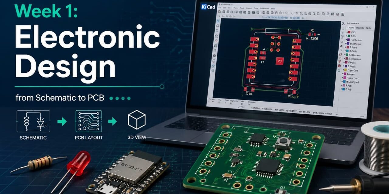
Introduction
The aim of this assignment is to learn the basics of electronic design. In this assignment, I learned about different electronic components such as a breadboard, resistors, LEDs, Arduino, ESP32, and an IR sensor. I made simple circuits and learned how each component works. I also learned how to connect the components correctly and test the circuits. This assignment helped me improve my basic knowledge of electronics and gave me more confidence in building simple electronic projects.
Individual assignment
Task:
In this assignment, I simulated various electronic circuits with an EDA tool. I designed and tested the circuits, ensuring they worked correctly. I also conducted ERC and DRC to identify and fix errors before starting the PCB design. This experience enhanced my circuit design and error-checking skills.
Group assignment
Task:
In the group assignment, we had to observe a microcontroller’s operation using lab test equipment. We measured voltage and current at various circuit points and checked the microcontroller’s performance. This helped us learn to use the test equipment and confirm the circuit’s operation.
Electronic Design:-
Electronic design is the process of making electronic circuits using different electronic components. It starts with drawing a circuit diagram and choosing the required components. After that, the circuit is tested using simulation to check if it works properly. ERC and DRC are used to find and fix errors before making the PCB. Then, the PCB layout is created for the final circuit. Electronic design helps to make safe, reliable, and good-quality electronic devices. It also saves time and reduces mistakes by checking the circuit before manufacturing. By learning electronic design, I understood how different electronic components work together in a circuit. It also improved my circuit design, testing, and problem-solving skills. This knowledge will help me build better electronic projects in the future.
basic concepts :-
Basic Concepts :-
What is Current?

Electric current is the flow of electric charge through a wire or a circuit. It flows only when there is a complete path called a closed circuit. Current moves from one point to another and helps electronic devices work properly. It is measured in Ampere (A) using an ammeter. A battery or power supply provides the energy needed for current to flow. If too much current flows in a circuit, it can damage electronic components. That is why resistors and other protection devices are used to control the current. Current is one of the most important concepts in electronics because every electronic circuit needs it to work.
Types of Current:- Direct Current and Alternating Current
Direct Current (DC) flows in one direction and is stable. It is often used in batteries, mobile phones, laptops, and other electronic devices. The positive and negative sides in DC remain the same.
Alternating Current (AC) flows in two directions and changes direction frequently. It’s used in homes, schools, and industries to power lights, fans, motors, and other appliances. AC comes from the main power line.
Voltage
Voltage is the force that pushes electric current through a circuit, like pressure moving water in a pipe. It is measured in Volts (V), and a battery or power supply gives voltage to the circuit. Without voltage, current can’t flow, and electrical devices won’t operate. Voltage is necessary for all electrical and electronic circuits.

Power
Power is the amount of electrical energy used in a circuit. It shows how fast electrical energy is used. Power is measured in Watts (W). It depends on voltage and current. If the voltage or current increases, the power also increases.
Resistance
Resistance is the force that stops or reduces the flow of electricity.
It controls how much current can pass through a wire or circuit.

Ohm’s Law
Ohm’s Law states that the current flowing through a conductor is directly proportional to the applied voltage and inversely proportional to the resistance, provided the temperature remains constant. Its formula is V = I × R.

Electronic Components:-
1.LED
LED (Light Emitting Diode) is a small electronic device that lights up when electricity flows through it. It uses less energy, lasts a long time, and is often used in lights, TVs, computers, and electronic circuits.

2.Resistor
A resistor is an electronic part that limits electric current in a circuit, protecting other components and ensuring safety. It’s a common component in electronics that controls current flow. Without a resistor, too much current can damage parts. Resistors come in different values, measured in ohms (Ω), and usually have colored bands to show their value. They are small, cheap, and easy to use, found in LED circuits, chargers, televisions, computers, mobile phones, and other devices, helping circuits work safely.

3.Push Button
A push button is an electronic switch that is used to open or close an electrical circuit when it is pressed. It is simple to use and works only while the button is being pressed. Push buttons are commonly used in doorbells, calculators, remote controls, toys, and electronic projects. They are available in different sizes and colors and help control the flow of electricity in a circuit.

4.Switches
A switch is an electronic device used to turn an electrical circuit ON or OFF. It controls the flow of electricity by opening or closing the circuit. Switches are easy to use and are found in homes, schools, offices, and electronic devices. They are commonly used in lights, fans, appliances, and electronic projects. Different types of switches are available for different applications.

5.Capacitor
A capacitor is an electronic component that stores electrical energy for a short time and releases it when needed. It helps make the power supply smooth and stable. Capacitors are commonly used in electronic circuits, TVs, computers, mobile phones, radios, and power supplies. They are available in different sizes and values for different applications.

5.Diode
A diode is an electronic component that allows electric current to flow in only one direction. It blocks the current from flowing in the opposite direction. Diodes are used to protect electronic circuits and convert AC to DC. They are commonly used in power supplies, chargers, TVs, radios, and many other electronic devices.

6.Transistors
A transistor is an electronic component that is used to control or amplify electric current. It works like an electronic switch and is one of the most important parts of electronic circuits. Transistors are commonly used in computers, mobile phones, TVs, radios, amplifiers, and many other electronic devices. They help electronic circuits work efficiently and reliably.

7.Sensors
A sensor is an electronic device that detects or measures things like light, heat, motion, or distance. It sends this information to a device. Sensors help devices work automatically by detecting environmental changes. There are various types of sensors for different purposes, such as measuring temperature, light, or motion. They are small, accurate, and easy to use, found in mobile phones, cars, smart homes, robots, and security systems. Sensors also operate automatic doors, street lights, and home appliances, improving safety, saving energy, and making devices smarter and more efficient.

Electronic Components Types:
Based on mounting type
SMD(Surface Mount Device)
SMD components are small electronic parts that are mounted directly on the surface of a PCB. They are widely used in modern electronic devices because they save space.
Through Hole
Through-hole components have long metal leads that are inserted into holes on a PCB and soldered. They are easy to use and are commonly used in learning projects and repairs.

Based on functionality type
Active Components
Active components are electronic parts that need a power supply to work. They can control, amplify, or switch electrical signals. These components play an important role in electronic circuits. Common examples of active components are transistors, ICs, LEDs, and diodes.

Passive Components
Passive components are electronic parts that do not need a separate power supply to work. They cannot amplify electrical signals but help control, store, or reduce electrical energy in a circuit. Common examples of passive components are resistors, capacitors, and inductors.
Group assignment
We used lab equipment to observe operations of an embedded microcontroller.
Multimeter


A multimeter is a tool for measuring electrical values in a circuit. It measures voltage (V), current (A), and resistance (Ω). It’s easy to use and helpful for testing electronic circuits.
A multimeter helps find faults in electrical and electronic devices. It is used to check batteries, wires, fuses, LEDs, resistors, capacitors, and other components. It gives accurate measurement results and helps repair circuits safely. It is simple to use and is suitable for beginners. A multimeter can also be used to check circuit continuity. This helps find broken wires or loose connections. It saves time during testing and repair work. Multimeters are available in digital and analog types. They are commonly used by students, electricians, technicians, and engineers. A multimeter is one of the most important tools for learning and working with electronics.
Testing a Voltage, Current Multimeter
In our group assignment, we used a digital multimeter to measure voltage and current. First, we switched on the multimeter and selected the correct mode. We connected the probes to the circuit carefully. Then, we measured the voltage and noted the reading. After that, we measured the current and recorded the result.
We checked that all connections were correct before taking the measurements. We followed the safety rules while using the multimeter. We observed the readings carefully and wrote them in our record book. We compared the measured values with the expected values. This activity helped us understand how a multimeter works. It improved our practical knowledge of electrical measurements. We also learned how to use a multimeter safely and accurately in electronic circuits.


Simulate a Circuit in Tinkercad
to create, simulate, and test electronic circuits online before buliding it in real life.


EDA (Electronic Design Automation)
EDA (Electronic Design Automation) is software used to design, draw, and test electronic circuits on a computer. It helps create circuit diagrams and PCB layouts easily. EDA tools save time and reduce design mistakes.
EDA software is easy to use and is helpful for beginners. It allows users to test circuits before building them. This helps find and fix mistakes early. EDA tools improve learning and make circuit design faster. They are used in schools, colleges, and electronic industries. Students use EDA software for projects and practical work. Engineers use it to design professional electronic circuits and PCBs. Popular EDA software includes Tinkercad, KiCad, EasyEDA, Eagle, and Altium Designer
KiCad
Why I choose KiCad?
KiCad is a free and open-source PCB design software. It is easy to use and has all the tools needed to design a PCB. Compared to many other PCB design software, KiCad does not require a paid license. It supports schematic design, PCB layout, and 3D viewing in one place. It also has a large library of electronic components. The software works on Windows, Linux, and macOS. KiCad is a good choice for students, beginners, and professionals because it is reliable, easy to learn, and completely free.
Information About Kicad:-
KiCad is a free and open-source software used for designing Printed Circuit Boards (PCBs). It helps users create circuit schematics and PCB layouts in an easy way. The software includes many useful tools for PCB design and also provides a 3D view to check the board before manufacturing. KiCad has a large library of electronic components, and users can also add custom components if needed. It is easy to learn and is widely used by students, hobbyists, and professional engineers for PCB design.
Step by step process to download kicad:-
Step 1:- Dowload Kicad
I searched ‘Download kicad for windows’ on Google

Step 2:- open the First website
Then i open the first website

step 3:- Then Click on Alibabacloud
After opening the website, click on Alibabacloud. The download will start auotmatically.

step 4:- Install kicad
After downloading, open setup file and complete the installation process.

Step 5:- Open Kicad
After installation was complete, I Open Kicad and explored its interface including schematic editor and PCB editor.

Step 6:- Download Fab library
To use Fab Academy components, I download the fab library from Github.

Step 7:- Extract the fab library
After downloading the fab library, I extracted the zip file to access the library and files.

Step 8:- Add symbol library of fab academy.
I opened KiCad and went to the Schematic Editor. Then, I opened Preferences > Manage Symbol Libraries and added the Fab component library.

step 9:- Add Footprint Library
I opened the PCB Editor and followed the same process to add the Fab footprint library through Preferences > Manage Footprint Libraries.

step 10:- ready for PCB Design
After adding both libraries, I can now use the Fab components and footprints to design PCBs in KiCad.

I added components needed for cicuit

And connected them according to the circuit diagram.

After completing all the connections, I ran the Electrical Rules Checker (ERC) to verify the schematic. The ERC checked the circuit for connection errors and missing links. It helped me identify and fix any problems before moving to the PCB design. This step ensured that the schematic was correct and ready for the next stage.

After checking the schematic, I opened the PCB Editor and updated the PCB from the schematic. Then, I placed the components in the correct positions and routed all the connections. Finally, I checked that all the connections were correct and the PCB design was complete.

After routing all the connections, I added the Edge Cuts to define the shape and size of the PCB board.

I ran the Design Rules Checker (DRC) to check for any errors in the PCB design. The DRC helped me find and fix design issues, ensuring that the PCB layout was correct and ready for manufacturing.

Finally, I opened the 3D Viewer to see the final PCB design. It helped me check the overall appearance of the PCB and confirm that all the components were placed correctly.

Indiviual Assignment
In my individual assignment, I completed the given task by following all the steps carefully. This activity helped me understand the topic better and improve my practical skills. I learned how to use the required tools correctly and complete the work step by step. I also learned how to find and fix small mistakes during the work. This assignment gave me hands-on experience and improved my confidence. It also helped me improve my problem-solving skills and practical knowledge.
Paper Circuit
A paper circuit is a simple electronic circuit made on paper. It uses conductive tape, electronic components, and a battery to make the circuit work. It is easy to build and helps beginners learn the basics of electronics. Paper circuits are a good way to understand how components are connected and how a circuit works. They are simple, low-cost, and useful for learning.


Soldering on zero PCB
Soldering on a Zero PCB is a simple way to build electronic circuits permanently. A Zero PCB has small holes where electronic components are placed and soldered together. Soldering creates strong electrical connections between the components. It helps make the circuit neat, reliable, and easy to test. Zero PCB is commonly used for prototype projects, learning electronics, and small circuit designs.


Detect Object using IR Sensor
In this activity, I connected an IR sensor, an LED, and an Arduino. The IR sensor was used to detect a nearby object. When the sensor detected an object, it sent a signal to the Arduino. The Arduino processed the signal and made the LED blink. When no object was detected, the LED remained off. This activity helped me understand how sensors communicate with a microcontroller. I also learned how to connect the components correctly and upload the program to the Arduino. It gave me practical experience in object detection and improved my understanding of basic Arduino programming.


PCB (Printed Circuit Board)
In this step, I created the circuit in the KiCad Schematic Editor. First, I added the Seeed Studio XIAO ESP32-C3, a 1206 resistor, and a 1206 LED from the component library. Then, I connected all the components using wires according to the circuit design.

In this step, I created the circuit in the KiCad Schematic Editor. First, I added the Seeed Studio XIAO ESP32-C3, a 1206 resistor, and a 1206 LED from the component library. Then, I connected all the components using wires according to the circuit design.

After fixing all the required connections, I ran the Electrical Rules Checker (ERC) again. This time, the schematic showed 0 errors and 0 warnings, which confirmed that all the connections were correct. The circuit was now ready to be updated to the PCB Editor for the PCB design process.

After updating the schematic to the PCB Editor, I placed all the components in their required positions. The blue connection lines showed where the PCB tracks needed to be routed. I arranged the components properly to make the PCB layout simple and neat. This step helped me prepare the board for the routing process.

I arranged all the components in their required positions. Then, I routed the PCB tracks to connect all the components correctly. I also adjusted the layout to make the PCB neat and compact. This step helped me create the final PCB layout before checking it for design errors.

After completing the PCB layout, I ran the Design Rules Checker (DRC) to check the PCB for design errors and warnings. The DRC found a few issues, such as missing Edge Cuts and silkscreen warnings. I reviewed these messages and corrected the required changes. This step helped me make sure that the PCB design was ready for manufacturing.

After adding the Edge Cuts, I ran the Design Rules Checker (DRC) again. This time, the PCB showed 0 errors, which confirmed that the board outline was correct. Only a few silkscreen warnings remained, which did not affect the PCB connections. This step helped verify that the PCB design was ready for the final review and manufacturing.

Finally, I opened the 3D Viewer to see the final PCB design. It helped me check the overall look of the PCB and the placement of all the components. This step confirmed that the PCB design was ready.