Introduction:
The Vibro Thermal Disinfector (VTD) is a machine developed at Vigyan Ashram for disinfecting grains like wheat and rice without using any chemicals. It works on two simple principles — heat and vibration. You can read about the original VTD design here.
Grains are poured from a hopper at the top and travel through a series of vibrating trays inside a heated chamber. By the time grains exit from the bottom, they are disinfected by the heat they were exposed to during their journey.
Basic Design:
The machine consists of:
- A hopper at the top where grains are fed
- 6 vibrating trays arranged in a zigzag pattern inside a heated chamber
- A vibrator motor with an eccentric weight that creates vibration
- A heating element that maintains temperature between 55-70°C
- An outlet at the bottom from where disinfected grains are collected
The vibration is created by an eccentric weight attached to the motor shaft. Since the weight is unbalanced, it creates a rotating force when the motor runs which causes the entire frame and trays to vibrate. This vibration combined with the slight slope of the trays makes grains travel forward and downward through all 6 trays.
The Problem:
For proper disinfection, grains need to spend at least 8 minutes inside the heated chamber. However currently grains were passing through in just 75 seconds — which is far too fast for effective disinfection.
What We Tried:
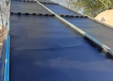
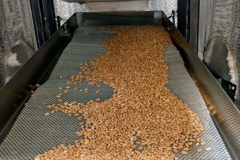
To increase the residence time of grains inside the machine, we decided to add iron mesh on the trays. The idea was that mesh would create a rougher surface than plain MS sheet, slowing down grain movement and increasing the time grains spend inside the heated chamber.
We started by adding mesh on the first and second trays to observe the effect- are as follows.
Observations:
During the trials we made several interesting observations:
- When the machine was started, grains were accumulating on the right side of the trays due to vibration direction
- Grains were also sliding below the mesh instead of travelling on top of it
- To fix both these issues we taped the mesh to the trays to hold it firmly in place
After adding mesh on two trays the residence time increased from 75 seconds to around 3 minutes 40 seconds — a significant improvement but still short of the 8 minute target.
Mesh Size Experiment:
We also experimented with different mesh sizes. The current mesh has a diagonal of approximately 2.20mm which gives a hole size of around 1.55mm — smaller than the wheat grain width of 3-4mm so grains cannot fall through.
When we tried a smaller mesh size, we observed that wheat grains were slipping rather than percolating through the mesh. This is because smaller mesh creates a smoother surface, reducing friction. The 2.20mm mesh proved better as it creates a rougher surface giving more resistance to grain movement.
Interesting Finding:
One interesting observation was that on plain MS trays grains slide smoothly, but on the mesh surface grains bounce while travelling. This bouncing is actually beneficial as grains get exposed to heat more evenly from all sides during their journey!
Grains falling from mesh and tray
23-29/5/26
Guide: Arun Dixit
Optimization of Grain Residence Time Through Flow Behaviour Studies
Initial Efforts to Increase Residence Time
After measuring the residence time of grains within the Vibro Thermal Disinfector (VTD), it was observed that grains were passing through the system in approximately 75 seconds. Since a longer residence time was required for effective disinfestation, several modifications were explored to reduce the grain conveying rate.
Hopper Cone Modification
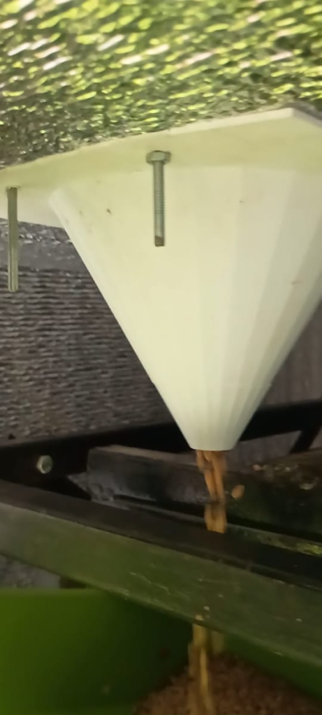
The first approach focused on controlling the feed rate of grains entering the VTD. A conical attachment was introduced inside the hopper to regulate the flow of grains into the first tray.
The modification reduced the amount of grain entering the system at a given time and helped maintain a more controlled feed rate. During the trials, a feed rate of approximately 550–600 g/min was achieved.
Installation of Tray Outlet Stoppers
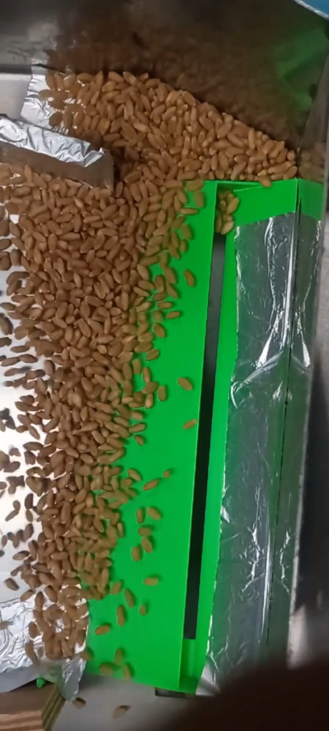
In addition to regulating the inlet flow, small stoppers were installed near the outlet of the trays. The objective was to reduce the amount of grain discharged from each tray and increase the time spent by grains before moving to the subsequent tray.
This modification provided a slight increase in residence time and helped in understanding how grain movement could be influenced by controlling discharge conditions.
Iron Mesh Modification
Following the initial trials, iron mesh was installed on Tray 1 and Tray 2 to further restrict grain movement. The mesh created resistance to grain flow and successfully increased the residence time of grains within the VTD.
The experiment confirmed that modifying the tray surface could effectively slow down grain transport. However, it was observed that different grain varieties would require different mesh sizes. This limitation reduced the practicality of the approach for a multipurpose system.
Limitations of the Iron Mesh Approach
Although the iron mesh increased the residence time, certain practical limitations were identified. Different grains have different sizes and shapes, and a mesh suitable for one grain type may not perform effectively for another.
This would require changing the mesh whenever a different grain is processed, reducing the versatility of the system. Frequent replacement of mesh would also increase operational complexity and maintenance requirements.
Development of Zig-Zag Grain Path
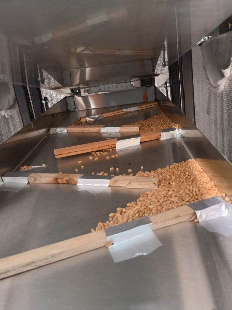
To overcome the limitations of the iron mesh, a different approach was investigated. Wooden strips were arranged on Tray 3 and Tray 4 in a zig-zag configuration so that grains were required to travel a longer path before reaching the tray outlet.
Ten wooden strips, each approximately 10 inches long and 1 cm high, were attached to the trays using tape. Five strips were fixed on each side of the tray at intervals of approximately 5 inches. The strips were placed at an angle of about 20° in a zig-zag arrangement so that the grains were forced to move from one strip to the next, increasing the distance travelled and consequently increasing the residence time inside the machine.
Unlike the mesh, this approach was independent of grain size and aimed to increase residence time by modifying the flow path rather than restricting grains through openings.
Results and Observations
The zig-zag arrangement produced a substantial increase in residence time. Prior to modification, grains required approximately 19 seconds to pass through an individual tray. After the installation of the zig-zag arrangement, the residence time increased to nearly 90 seconds on Tray 3 and around 70 seconds on Tray 4.
During operation, grain accumulation was observed behind some of the wooden strips. Although the arrangement increased residence time significantly, the accumulation behaviour indicated that further investigation of grain flow patterns would be necessary to develop an improved solution.
29/05-05/06/26
Analysis of Previous Tray Arrangement
Limitations Observed in Existing Setup
After testing the zig-zag pattern modification, an increase in grain residence time was observed. However, during further observation of grain movement, certain limitations were identified.
The grains were able to follow the zig-zag path, but the movement was not uniform throughout the tray width. The wooden strips created a defined flow path, causing grains to accumulate in certain regions. Due to this accumulation, only the upper layer of grains showed continuous movement, while the lower layer remained relatively stagnant.
This created concerns regarding effective utilization of the tray area. Although the tray provided a larger surface area for grain treatment, the actual active flow region was limited, reducing the effective utilization of the available tray area.
The observations suggested that improving residence time only by increasing the flow path was not sufficient. A better grain movement pattern was required where the grains could remain longer inside the system while also maintaining continuous movement and better exposure to the vibration.
Requirement for Modification
Based on these observations, it was decided to study and modify the vibration transfer mechanism of the system. The aim was to improve the movement of grains by increasing the effectiveness of vibration rather than relying only on physical obstructions on the tray.
Study of Existing Vibration Arrangement
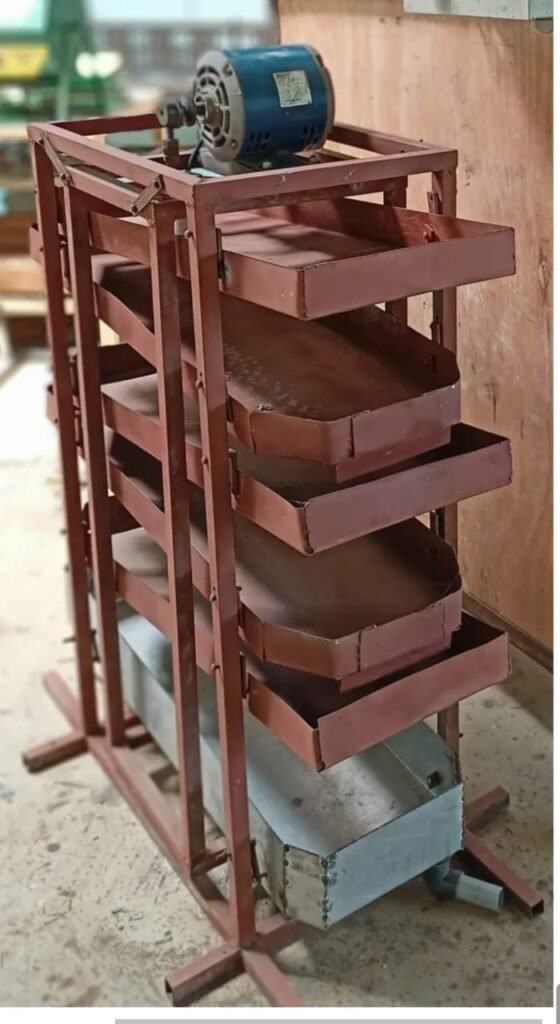
The existing VTD consisted of an outer frame carrying the trays and an inner frame on which the eccentric motor was mounted. The vibration generated by the motor was transferred through the structure.
During analysis, it was observed that the tray assembly was not directly connected to the vibrating frame. Therefore, the transfer of vibration to the grains was limited by the existing arrangement.
To improve the effectiveness of vibration, a modification in the tray mounting arrangement was planned.
Transfer of Trays to Vibrating Frame
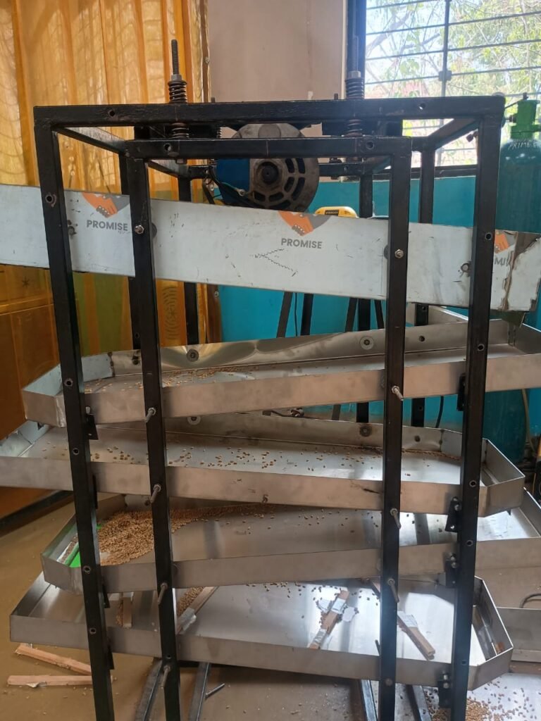
As a modification, the trays were shifted from the outer frame and attached to the inner vibrating frame along with the motor assembly.
This change was implemented so that the vibration generated by the eccentric motor could be directly transferred to the trays and grains. The expected outcome of this modification was improved grain agitation, better vertical movement, and more uniform flow across the tray surface.
Modification of the Motor Mounting System
During the study of the vibration mechanism, it was observed that the eccentric motor was mounted on thin iron strips, which were flexible and tended to bend during operation. As the motor rotated, these strips absorbed part of the vibration, reducing the effective transfer of vibration to the frame.
To improve the vibration transmission, the flexible iron strips were replaced with a rigid MS angle section, providing a stronger and more stable support for the motor. This ensured that the vibrations generated by the motor were effectively transferred to the vibrating frame.
In addition, it was observed that the motor mounting was slightly misaligned from the beginning. This misalignment could affect the balance of the rotating eccentric load and lead to uneven vibration. Therefore, the motor was properly aligned and securely fixed to the frame before further testing.
To further enhance the vibration, the eccentric load was increased from approximately 50 g to 250 g. The increased eccentric mass was expected to generate higher vibration amplitude, thereby improving grain movement and increasing the residence time inside the machine.
Introduction of Compression Spring Support
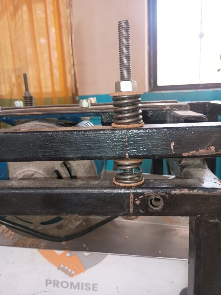
After shifting the trays to the inner frame, compression springs were installed between the inner and outer frames.
The springs act as a flexible support system, allowing the inner frame and trays to vibrate while the outer frame remains stationary. This arrangement is expected to provide better control over vibration movement compared to the previous rigid support arrangement.
The modified setup will now be evaluated to study its effect on grain movement, residence time, and distribution across the trays.
Spring Selection
The objective of introducing springs into the system was to improve the transmission of vibration from the eccentric motor to the tray assembly by allowing controlled vertical oscillation of the inner frame.
The total vibrating mass, including the inner frame, trays, and maximum grain load, was approximately 60 kg. Since four compression springs were used, the total load was assumed to be equally distributed among them.
Calculation
Weight of inner frame with trays = 50 kg
Maximum wheat load = 10 kg
Total vibrating mass = 60 kg
Number of compression springs = 4
Total vibrating mass:m=50+10=60 kg
Total load:W=mg=60×9.81=588.6 N
Load on each spring:F=4588.6=147.15 N
Therefore, each spring was required to support approximately 147 N (≈15 kg) under static loading.
Considering this loading requirement, motorcycle suspension compression springs were selected because they are readily available, economical, and specifically designed to withstand repeated dynamic loading and vibrations. These springs provided adequate support to the vibrating frame while allowing sufficient vertical movement during machine operation.
The final suitability of the selected springs was verified experimentally through machine trials
Further experiments will focus on optimizing the vibration conditions and improving grain flow without creating stagnant zones or narrow flow paths.
06/06-15/06/26
Need for an Adjustable Tray Inclination Mechanism
In the existing Vibro-Thermal Disinfector, the trays were fixed at an inclination of approximately 5°. Although this arrangement allowed the grains to move from one tray to another, it did not provide the flexibility to study the effect of tray inclination on grain flow characteristics.
During the grain flow experiments, it was observed that tray inclination plays a significant role in determining the residence time of grains inside the machine. A higher inclination causes the grains to move more rapidly, reducing their residence time, whereas a lower inclination slows down the grain movement, increasing the residence time. Since different grains possess different physical properties such as size, shape, density, and surface friction, a single fixed inclination cannot provide optimum performance for all grain types.
Therefore, an adjustable tray inclination mechanism was designed and fabricated. The mechanism allows the inclination of the entire tray assembly to be varied easily without dismantling the machine. This modification enables systematic experimentation to determine the optimum tray angle for different operating conditions and grain types, while also providing flexibility for future optimization of the Vibro-Thermal Disinfector.
Development of Adjustable Tray Inclination
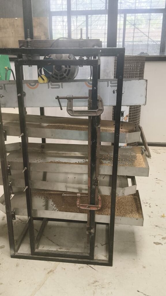
During earlier experiments, the trays were maintained at a fixed inclination of approximately 5°. Since tray inclination directly affects grain velocity and residence time, it was decided to develop a mechanism that would allow easy adjustment of the tray angle.
A threaded adjustment mechanism was fabricated and installed on both sides of the frame. By rotating the threaded rod, the position of the vibrating frame can be altered, by a range of 0 – 15 degrees thereby changing the inclination of all trays simultaneously. This arrangement eliminates the need for repeated fabrication whenever a different inclination angle is to be tested.
The adjustable mechanism enables systematic experimentation to determine the optimum tray inclination for different grain flow conditions.
15/06 – 28/06/2026
Optimization of Residence Time
After completing the modifications to the vibration system and incorporating the adjustable tray inclination mechanism, the grain flow was evaluated under different operating conditions. By optimizing the tray inclination and vibration characteristics, the grains remained inside the Vibro-Thermal Disinfector for 8 minutes and 35 seconds, successfully achieving the target residence time required for effective thermal treatment.
The improvement in residence time demonstrated that the modifications made to the tray mounting arrangement and vibration support system were effective in controlling grain movement without introducing significant flow obstructions.
Initial Thermal Testing
With the desired residence time achieved, the next phase of the project focused on evaluating the thermal performance of the Vibro-Thermal Disinfector.
The heating system was operated by setting the controller temperature to 70°C. After allowing the machine to reach a stable operating condition, temperature measurements were taken at different locations within the machine as well as from the treated wheat grains at the outlet.
The measured temperatures are summarized below.
| Parameter | Measured Temperature |
|---|---|
| Heater Set Temperature | 70°C |
| Temperature inside the machine | 56–57°C |
| Grain Temperature | 41–47°C |
2/07 – 7/07/2026
Thermal Testing
Test Conditions
| Parameter | Value |
|---|---|
| Heater Set Temperature | 100°C |
| Thermostat Set Temperature | 80°C |
| Tray Surface Temperature | 62–63°C |
| Grain Outlet Temperature | 48°C |
| Grain Sample Mass | 200 g |
| Water Volume | 250 mL |
| Water Initial Temperature | 26°C |
| Water Final Temperature | 30.5–31°C |
| Temperature Rise of Water | 4.5–5°C |
Heat Transfer Calculation
The heat absorbed by the water is calculated using:
Where,
- m=250 g (mass of water)
- c=4.186 J/g°C
- ΔT=4.5 to 5∘C
Case 1: Temperature rise = 4.5°C
Q=250×4.186×4.5 Q=4709 J
Case 2: Temperature rise = 5°C
Q=250×4.186×5 Q=5232.5 J
Therefore,
Heat transferred from the grains to the water = 4.71–5.23 kJ
Heat Absorbed per Unit Mass of Grain
Since the grain sample weighed 200 g,
For a 4.5°C rise:2004709=23.5 J/g
For a 5°C rise:2005232.5=26.2 J/g
Therefore,
Specific heat gained by the grains = 23.5–26.2 J/g
or
23.5–26.2 kJ/kg
Observation
The thermal testing demonstrated that the Grain Disinfectant Unit successfully transferred heat to the grains during their passage through the machine. Although the heater was set to 100°C, the tray surface temperature stabilized at 62–63°C, and the wheat grains reached an outlet temperature of approximately 48°C. The calorimetric test, performed by immersing the heated grains in water, indicated that the grains transferred approximately 4.7–5.2 kJ of thermal energy to the water sample. These results confirm that the grains absorbed a measurable amount of heat during processing and provide a baseline for future optimization of the heating system.
Biological Testing
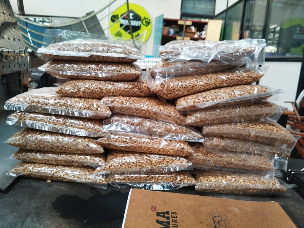
After completing the thermal testing, a preliminary biological study was initiated to evaluate the effectiveness of the Grain Disinfectant Unit in preventing the development of storage insects during grain storage.
Wheat grains were passed through the machine under the optimized operating conditions. During the experiment, the heater temperature was maintained at 100°C, the thermostat was set at 80°C, the tray temperature reached approximately 62–63°C, and the grains attained an outlet temperature of about 48°C.
Following the thermal treatment, the grains were allowed to cool to room temperature. A total of 20 samples, each weighing 450 g, were packed in airtight plastic bags and properly sealed. These samples are being stored under identical conditions.
One packet will be opened every week to observe any signs of insect emergence, egg hatching, or larval development. The observations will help determine whether the thermal treatment is effective in suppressing insect infestation during storage.
The biological testing is currently in progress, and the results obtained from the weekly observations will be used to assess the long-term effectiveness of the Grain Disinfectant Unit.
08/07 – 23/07/2026