Introduction
What are Black soldier flies (BSF) ?
The ‘Hermetia illucens’, also known as black soldier fly (BSF) are long black coloured flies. These flies have a huge appetite at the larval stage, therefore used as decomposers of organic substrates to recycle manure, especially livestock waste; generate oil and protein rich feed for farm/pet animals and fish. Companies like AgriProtein, InnovaFeed and Protix produce them in their insect factories. They are harvested in grub composters. They are known to reduce organic chemical pollutants. Their excreta known as frass can be used as organic fertiliser directly. Research has also been carried out for purification of biomass with heavy metals.
Properties and life-cycle
They are about 16 mm long, black in colour and have metallic appearance (blue/green on thorax and red on the abdomen). It is a mimi fly, resembling the ‘organ pipe mud dauber’. Mating can occur after 2 days of being an adult. In order for the mating to occur the males require good lekking sites where they display their dominance. An adult female lays 206-639 eggs at a time, in small spaces or surfaces of decaying matter. The eggs take 4 days to hatch. The larvae are 1mm initially and can go upto 25mm and 0.1-0.22g and complete development in about 14 days. Being an insatiable feeder the larvae are known to decompose material quickly during this period in cool dark places. The larva finds dry sheltered places to initiate pupation which lasts for 1-2 weeks. The adults live for 47-73 day with food (nectar) and 8-10 day with water and stored fats.
Need for the project
In order to explore their applications they are being grown in a BSF chamber. More information about the BSF camber is available on the following blogs. This chamber needs to have the ambient environment conditions for the maximum yield of larvae. Based on existing literature the optimum conditions for their mating and growth were found out.
- Small holes to lay eggs (grub bins)- corrgurated cardboard/plastic.
- Tropical/subtropical climate for year-round breeding.
- Appropriate amount of heat and light is required.
- 20-40 OC, 99.6% oviposition at 27.5 OC- 37.5 OC
- Quatrz-iodine lamps are used to stimulate mating
- In tropical climates, morning direct sunlight for emergence, mating, and egglaying and indirect sunlight for before and after mating.
- Humidity – 93% emergence at 60-70%
Objectives
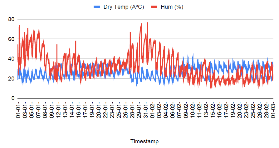
- Data logging – Continuous monitoring of temperature and humidity data
- Automated regulation – regulation of temperature and humidity
Ideation
Based on the requirements research was carried out ideas were generated for data logging and regulation of environment conditions.
Data logging
To design an electronic system for the data logging and automating the system ESP32 micro-controller seems to be the best fit due to its in-built WI-FI connectivity, cost effectiveness and proven usefulness in the past IoT based projects in Vigyan Ashram. In order to measure the temperature and humidity, two different strategies could be implemented.
- Wet bulb and dry bulb temperature – This method was previously designed in Vigyan Ashram.This method uses two DS18B20 temperature probes, one as it is (dry bulb ) and the other is covered with a wet cotton sleeve that is dipped in water at the other end (wet bulb). The temperature is measured using the dry bulb and the humidity is calculated by applying a formula to the temperatures of the two probes.
- BME280 – This sensor is developed by Bosch to measure temperature, relative humidity and barometric pressure. It is perfect for mobile applications with low power consumption, good accuracy and fast response time. Based on past experiences, it was observed that the BME280 got damaged with time due to excess exposure to the outside environment. To solve this issue a protective cover was proposed to cover the BME to allow the measurement of humidity and temperature while protecting it from the outside environment.
To store the data generated by the sensors the data could be uploaded to a Firebase database. Firebase provides not only a database to upload, store and protect data but also allows to represent the data on a website that can be hosted using Firebase. More details about this system is available on the following blog.
Automated regulation
As the BSF require optimum temperature and humidity for maximum yield these conditions need to be regulated in the BSF chamber. For this different methods were proposed
- Heater- Using an AC/DC heater to increase the temperature
- Tungsten filament bulb- This bulb will produce light as well as heat to increase the temperature
- Fan- the fan will blow out the hot air inside the chamber along with the water vapor, which will result in the decrease in temperature and humidity
- Piezoelectric humidifier- A piezoelectric transducer vibrates with high frequency on the surface of water, converting the water to small mist droplets. This results in a increase in humidity and decrease in temperature.
- Boiling apparatus- A heater can be dipped into water to vaporize water in order to increase the temperature and humidity.
Initially only three methods were decided to be implemented, i.e. Tungsten bulb, fan and piezoelectric humidifier
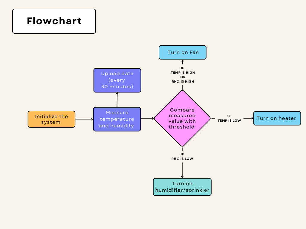
Workflow
- The environment parameters, temperature and humidity will be measured by the BME sensor every minute.
- The sensor will be housed in a PVC pipe with ceramic/metal filter at the end.
- These measurements will be stored in database online after every 30 minutes to get the required stats.
- The parameters will be checked and if they are outside the suggested range, the actuators will be actuated.
- The temperature will be increase by the use of a bulb
- The humidity will be increased by a sprinkler or a piezoelectric humidifier.
- The temperature and humidity will be decreased by the fan which blows the air outside the temperature.
Development of the system
Data collection
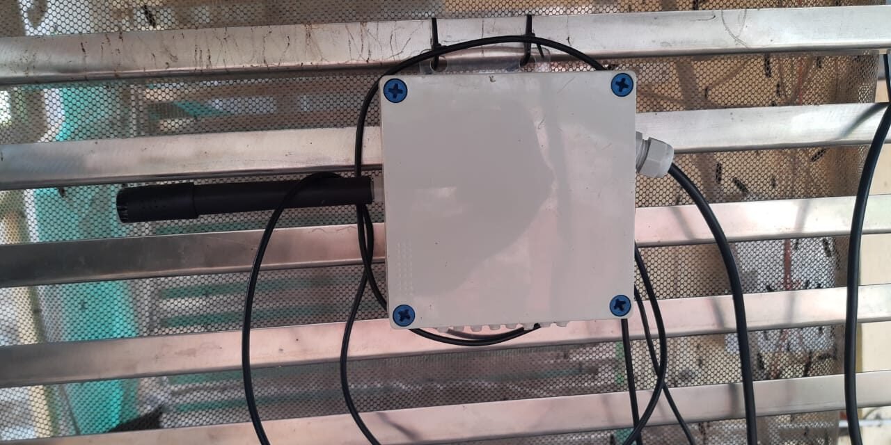
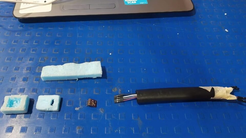
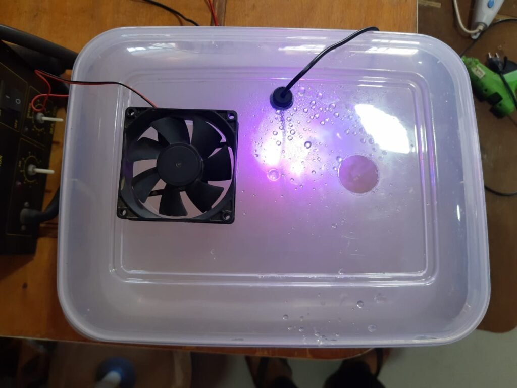
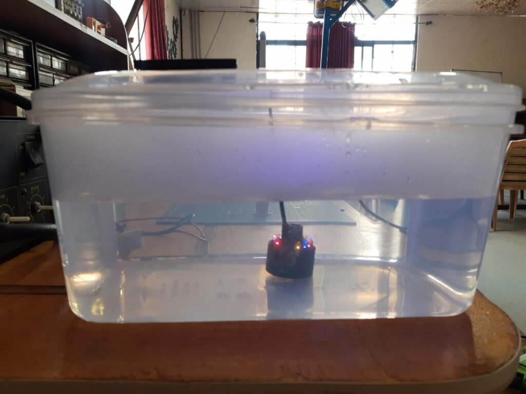
To collect the data from the BSF chamber the sensors were connected to ESP32 microcontroller. The BME280 has 4 pins, GND, VCC, SDA and SCL. The SDA and SCL pins are used for I2C communication with micro-controller. In this case it is connected to the 21 and 22 pin of the ESP32. The sensor was tested and provided consistent data and could be easily calibrated by giving a small offset to adjust it to the correct reading. To protect the BME 280 sensor a casing was designed frugally using PVC pipes. To allow the flow of water vapor to reach the sensor it needed to be covered with a breathable material at one end. Multiple materials were used to create the end.
- Ceramic water filter- A ceramic water filter used as an attachment for taps was used to cover the BME 280 sensor. The filter had a silicon based casing which fit well to the pipe and was sturdy but the presence of the filter as a protection caused a drastic change in the temperature (+5OC) and humidity (+18%) readings as compared to the naked sensor. This makes the ceramic filter inappropriate for protection.
- Foam – The foam used for aquaponic cultivation was repurposed to be used as a breathable material for BME protection. The foam was cut to fit the BME 280 sensor inside it and covered with tape. The casing failed to give the required results as there was a change in the temperature(+4OC) and humidity (+15%) values compared to the naked sensor.
- Perforated PVC pipes – Small holes were made in the PVC pipes to make it breathable. This arrangement gave the most reliable results. The sensor worked similarly with and without the over. This arrangement was finally implemented.

Data logging
To store the collected data a website was created and connected to firebase in a similar way developed previously. Please refer to the following blog for more details.
Automatic regulation
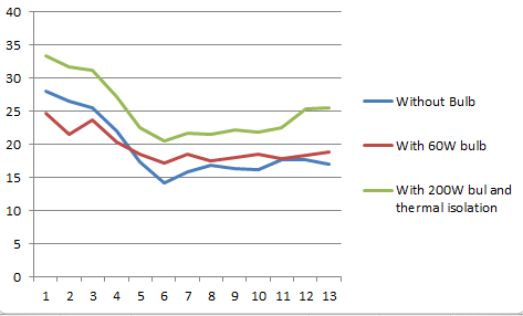
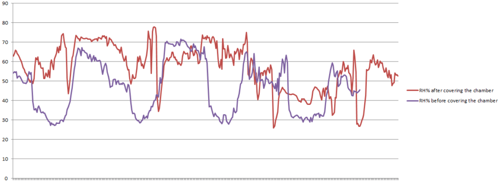
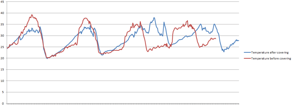
Based on the workflow described above the system was designed using a 5 V relay module, ESP32 and the actuation components. Initially the environment of the chamber was controlled using a 60W incandescent bulb. There was a definite increase in temperature observed but it did not meet the requirements. The reason was the well ventilated chamber with lack of thermal isolation. The heat did not spread over the chamber and was concentrated around the bulb only. To contain the heat within the chamber a layer of isolation was added on three sides completely with partial isolation on the fourth side. The forth side was left open in order to in order to allow sunlight in the morning during the mating period. The thermal isolation worked well but did not raise temperatures as much as required so a more powerful bulb of 200W was used to replace the 60W bulb. This show good temperatures that are maintained within the 30-35 oC temperatures.
Improvements required
- The ESP32 data logging system is not consistent and misses a few data points. The time period needs to be further optimised.
- The BME280 sensor and 2 probe sensor have generated enough data for comparison. BME280 gives stable readings but lower than 2 probe sensor. There needs to be a standard method of calibration.
- The protection for sensor needs to be refined.
- AHT0X series of sensors seems to be a good and cheaper alternative to BME280. Tests need to be conducted.
- With the summer approaching there is a need to regulate humidity in the chamber. System needs to be developed for the same.
Development of Humidifier
As mentioned earlier there is a need to regulate the humidity within the BSF chamber to get optimal larvae. With the summer approaching, the temperature is increasing, and as a result the humidity is decreasing. In order to tackle the problem there is a need to humidify the air in the BSF chamber. Therefore a humidifier was proposed to increase the humidity that would utilize a piezoelectric mist maker that will be used to generate mist and supply it to the BSF chamber.
Ideation
In order to increase humidity a mist maker was used. The mist maker is capable of producing cold mist. The mist maker is made up of a piezoelectric transducer that oscillates at high frequencies proportional to the high frequency electronic signals. The transducer when immersed in water has a few effects on it. The first one is the formation of tiny cavitation bubbles due to the rapid change in amplitude of the waves, leading to the bubbles being imploded onto the surface creating aerosols. The capillary waves created when broken result in the dispersion of small water droplets. These droplets are cool so decrease temperature and increase humidity. The humidifier also has a 12 DC fan that pushes the droplets through a pipe into the chamber. This step is necessary as the the weight of the mist formed is comparatively heavy and needs applied force to get it to the right place.

Material
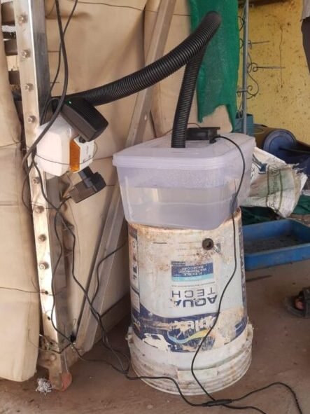
- Plastic container
- 24V DC Mist maker with adapter
- 12V DC CPU cooling fan with adapter
- Flexible plastic pipe
- AC socket box
Fabrication of the device
- After testing the working of the mist maker, and acquiring the resources, holes were cut through the top of the plastic container for the fan, mist maker wire and an opening for the mist to be transported out through a pipe.
- The fan, humidifier and the required DC adapters were connected and tested in the lab for different levels of water in the container.
On testing it in the lab the following results were obtained
| Height of water above the mist maker | Time taken | Volume of water converted to mist |
| 4.2 cm | 1 hour | 70 ml |
| 1.6 cm | 1 hour | 150 ml |
Field Testing
- An AC socket was connected to the control relay for the humidity. The required adapters were connected to this socket, and would be switched on automatically with decrease in humidity.
- The setup was installed outside the BSF chamber with the pipe carrying the mist into the chamber, pointed at the middle of the chamber at 1/3 rd the height of the chamber.
- Post the installing of the humidifier, the device provided a good water in the form of mist. The rate of addition of water to the BSF chamber by the humidifier was measured to 375 ml for 3 hours, i.e. up to 125 ml per hour.
- There was no significant increase in the humidity measured by the data logging system due to the humidifier. There are many possible reasons for this, rate of water diffusion/evaporation is quite high. The water provided is not sufficient and its density being less makes it rise to the top.
- On calculation it was discovered that the volume of the chamber was 1.347 m3 , which contains approximately 1.742 kg of air (assuming the density of air is 1.293 kg/m3).
- That means the water content at relative humidity 17% is 0.296 ml. and there is at least a need of 1l water in an ideal system where there is no loss of water by diffusion to reach 60%
- To find alternatives a home cooler was used to increase the humidity. It was capable of delivering 1l of water in an hour at high speed settings and 300ml at medium speed settings. It also resulted in increase of the humidity up to 50%.
- It seems like a better option and will be explored more to increase the humidity.
NOTE: The above can calculation was found to be wrong later on, hence the corrected calculations can be found below.
Updating the method for humidification.
Due to ineffective humidification by the humidifier, other alternatives are being looked into.
To increase the humidity multiple ideas were though of and tested.
Bubbling of water results in the formation of bubbles that will be released in the air through the surface of water. As the bubbles rise in the water they move upwards and burst resulting in small water droplets released into the air. Two method were used for bubbling. The first was using an aquarium aerator that was switch on for an hour and the loss of water was measured. The second method was using an aerotube attached to an air pump that blew air into the water. Both these methods were able to displace less than a few ml of water in an hour. This makes it an unfit method of increasing the humidity as it is much less than the previous method.
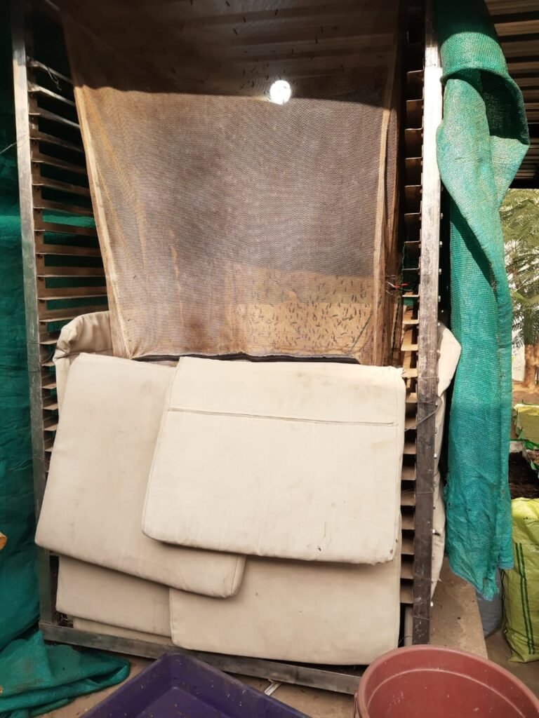
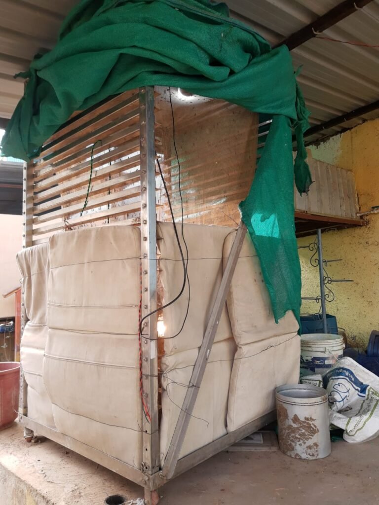
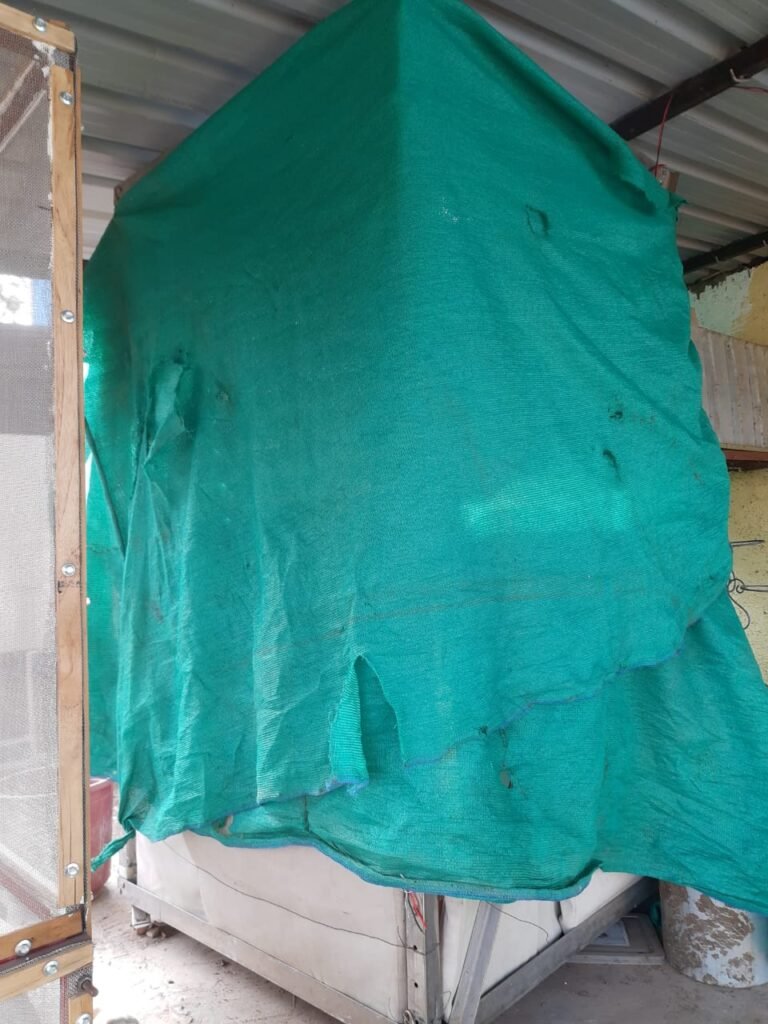
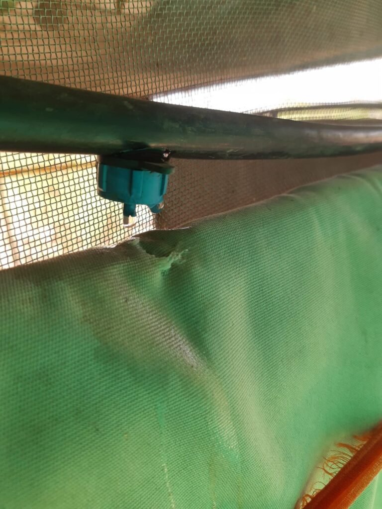
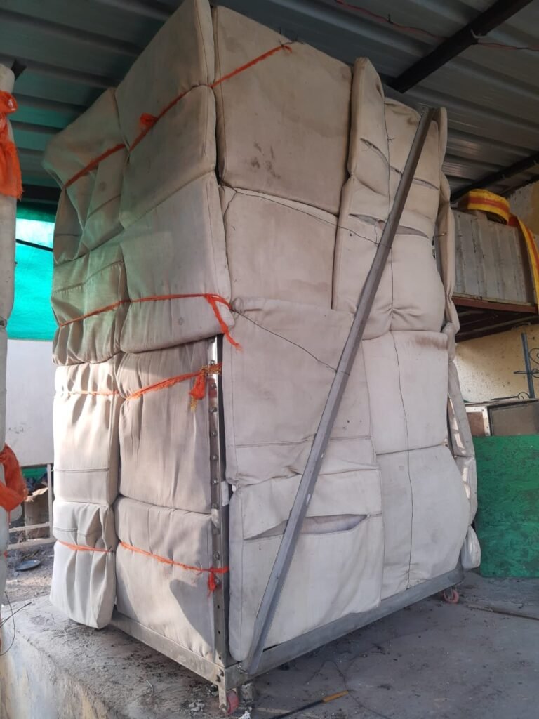
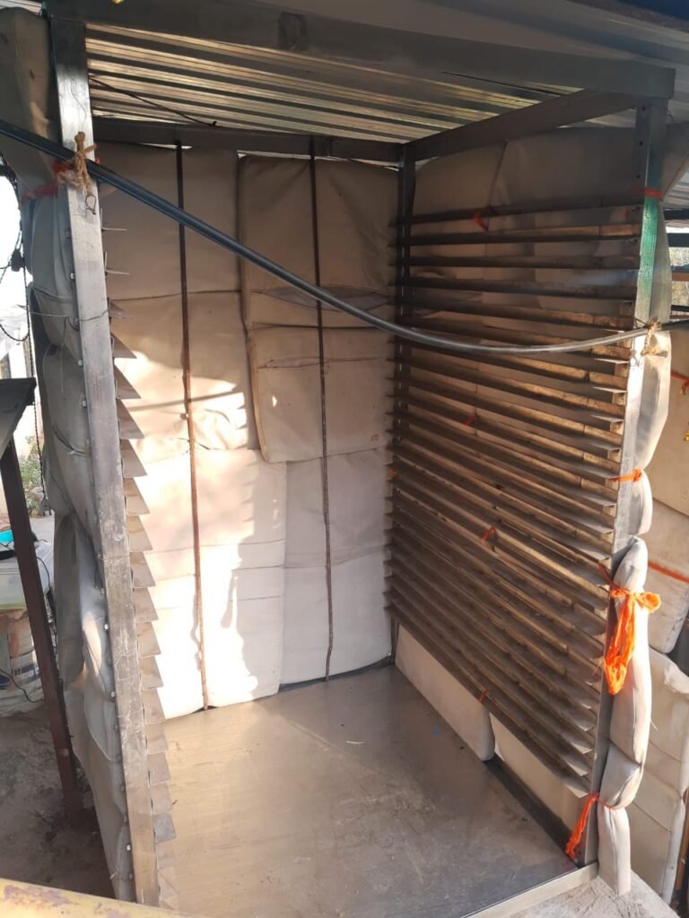
As an alternative to the humidifier the method of evaporative cooling is being explored to decrease the temperature and increase the humidity. This method can be implemented by providing wet surfaces around the chamber that can be wetted, followed by release of water by evaporation, resulting in the increase of the humidity in the surrounding. It being an inexpensive and promising method has been under experimentation. Currently the BSF chamber has been covered with insulating pads on 3 sides. The pads can be wetted in order to cause evaporative cooling. Pipes with drippers attached to a pump have been installed on top of the pads. These pumps are switched on until the pads are wet and are left to dry and cool down.
Redesigning the BSF data logger and automation device. (Version 2.0)
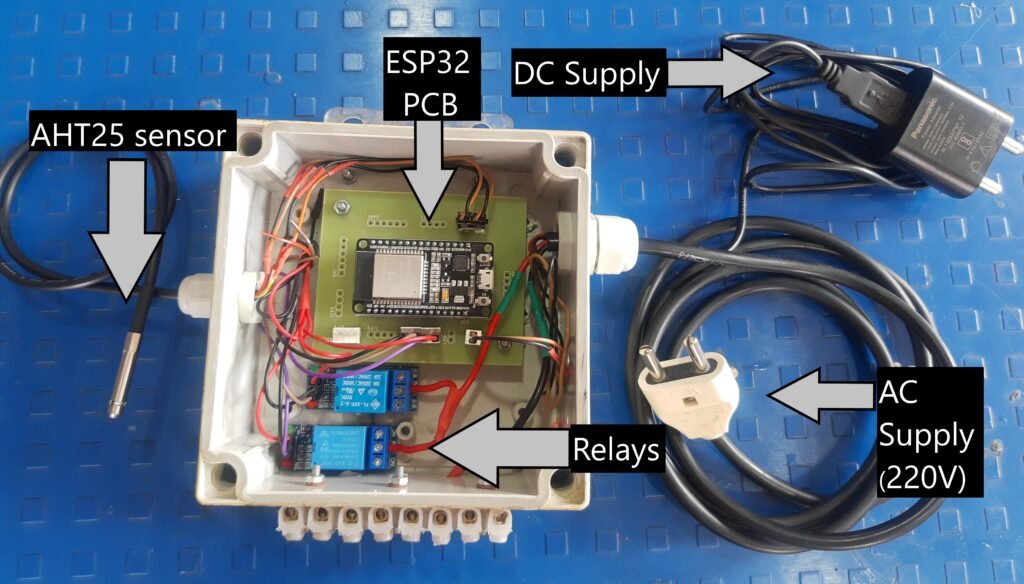
Initially the device was made by direct soldering of wires onto the ESP32 module. This version of the device was developed using PCB designed in the lab, and procured from a vendor. More information on this PCB will be mentioned in another blog. This PCB is a universal ESP32 shield that has pins to connect to different types of input and output devices following different modes of communications like I2C, SPI, UART, etc. This PCB is used in the project as we are utilizing AHT25 (I2C device) and relays. The new PCB was soldered with the required pins and installed to make it more standard, durable and helps in the easy replacement of parts in case of damage.

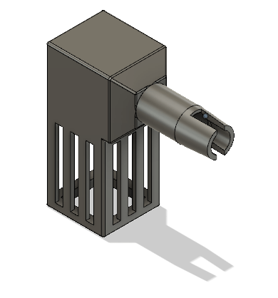
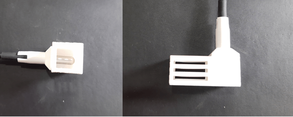
In order to protect the AHT sensor while allowing it to measure temperature and humidity a new design was made. This design contains a press fit mechanism that locks on to the sensor once inserted. The other end has an opening at 90O which is long and has slits on the side and bottom for the sensor to take better readings.
New methods for humidification
The previous method used for humidification was able to increase humidity up to only a certain level. To solve this new methods of humidification were explored
In order to increase humidity new methods proposed were bubbling and evaporative cooling through honeycomb structure.
Bubbling was tried out in a small experimental setup:
- First the volumetric airflow rate of the bubbler was determined by measuring the water displacement in an inverted bucket with aero-tube inside which was connected to the air pump.
| Initial weight (kg) | Final weight (kg) | Loss of water (kg) | Time (s) | Flow rate |
| 19.548 | 18.250 | 1.298 | 10 | 0.1298 |
| 18.386 | 14.300 | 4.086 | 10 | 0.4086 |
| 14.268 | 10.638 | 3.63 | 12 | 0.3025 |
| 21.105 | 16.640 | 4.465 | 10 | 0.4465 |
| 16.450 | 12.120 | 4.33 | 10 | 0.433 |
| 20.380 | 16.400 | 3.98 | 10 | 0.398 |
| 16.402 | 10.840 | 0.562 | 15 | 0.3708 |
| 20.485 | 11.898 | 8.587 | 20 | 0.42935 |
| Average | 0.365 ml/s |
| For, Temperature: 35OC and Relative Humidity: 27% Specific humidity: 0.00947 kg water/ kg dry air | For, Temperature: 35OC andRelative Humidity: 100% Specific humidity: 0.03658 kg water/ kg dry air |
Therefore, the resulting maximum driving force = 27.11 g
For, Density of air = 1.146 kg/m3 ; 0.001146 kg/liter
Average rate of water volumetric displacement = (0.365 x 60) = 21.9 liter/min
Therefore, the average mass flow rate of displacement of air is = (21.9 x 0.001146) = 0.02 kg/min
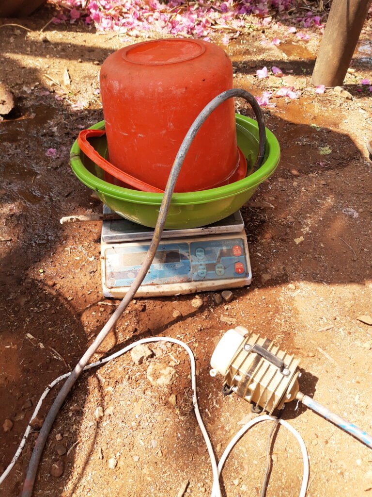
- Measurement of rate of evaporation by bubbling
The experiment was carried out on a weighing balance by placing a bucket filled with water on it. The bucket contained an aero-tube that bubbled air into the bucket.

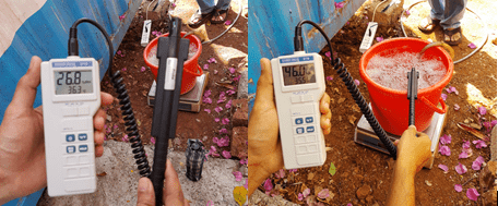
On comparing the ambient temperature and humidity with the bubbling apparatus, it was found out that the there was a difference of 0.7 OC and 19.2% in temperature and humidity respectively.
| Time (min) | Loss of water (g) |
| 39 | 46 |
| 40 | 46 |
Loss of water per minute = 1.165 g/minute
Calculating the requirement of water for the BSF chamber
| At, Temperature = 34.35 °C; Relative Humidity =33.73 % Using psychometric charts, Specific humidity = 0.01145 kg water/kg air Density of air at 34 °C = 1.149 kg/m3 Therefore, Specific humidity = 0.013156 kg water/m3 air Since, Volume of the BSF chamber = 2 m3 Water in the chamber = 0.026312 kg water ~26.312 g water | At, Temperature = 34.35 °C; Relative Humidity =33.73 % Using psychometric charts, Specific humidity = 0.0.02251 kg water/kg air Density of air at 34 °C = 1.149 kg/m3 Therefore, Specific humidity = 0.02586 kg water/m3 air Since, Volume of the BSF chamber = 2 m3 Water in the chamber = 0.05172 kg water ~51.172 g water |
In an adiabatic condition,
There is a requirement for an additional 24.86 g of water to reach the desired humidity in the chamber. This makes the humidifier an eligible device to increase humidity if the system is made adiabatic.
Calculating the humidity increase from the humidifier
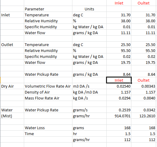
To calculate the humidity increase by the humidifier it was placed on a weighing balance and switched on to measure the loss of water. The temperature and humidity of the ambient conditions and the outlet of the humidifier were measured using a hygrometer. The airflow of the humidifier was changed by reducing the air resistance.
Reduction of water loss through chamber.
The water supplied through various methods to increase the humidity fails due to the excess loss of water from the chamber. This loss can be significantly reduced by decreasing the movement of air out of the chamber.
In order to do this translucent plastic sheets were used to cover the chamber from all sides leaving a slight gap on the bottom of one side for small amount of air flow and exchange of gases.
- Considering that the moist air is lighter and less dense than dry air, the humid air that has accumulated moisture becomes lighter and rises to the top. This traps the moisture for a longer time.
- Oxygen gas has a density of 1.429 grams/liter at the standard pressure and temperature while carbon dioxide has a density of 1.977 grams/liter. This means carbon dioxide is 1.383 times as heavy as oxygen and therefore, is more likely to settle down and escape from the gap, allowing fresh air to come in while letting the oxygen stay in the chamber.
Since the conversion rate of water to mist by the humidifier is greater than the water required in the chamber it can be used to increase the humidity.
- Previously, the humidifier was place outside the chamber and a pipe was directed into the chamber. This was forcing air from outside to the inside of the chamber resulting in the displacement of air.
- To tackle this problem, the humidifier will be placed inside the chamber with so as to circulate the air within the chamber. This will not allow air from outside to be forced inside, reducing the displacement of air.
- It will also add on the efficiency as the humid air will become more humid rather than making dry air humid.
- Additionally the removal of the pipe that directs the moist air from the humidifier is removed. This will result in less resistance to the airflow and hence a greater mass flow rate of the humid air into the chamber.
On conducting a trial with the humidifier and the plastic sheets, it increased the humidity successfully and rapidly to the required levels. It was noticed that some times the temperatures were rising to 38OC and also a decrease in the humidity. The pads used previously were supplied with water and made wet. This resulted in instantaneous decrease in temperature and increase in humidity. This is probably due to the evaporative cooling effect of the pads.
Final code (Visual studio)
/*
  This code is the one used on the ESP32 which is performing the measurements in the Black Soldier Flies project.
*/

//make sure Arduino IDE is not open when using VS code /!\ -> otherwise USB PORT COM problem will occur

/*
Example:
A fatal error occurred: Could not open COM8, the port doesn't exist
*** [upload] Error 2
*/


//uncomment the wifi you want to use
#define WIFI_WORKSHOP

#include <Arduino.h>
#if defined(ESP32)
  #include <WiFi.h>
#elif defined(ESP8266)
  #include <ESP8266WiFi.h>
#endif
#include <Firebase_ESP_Client.h>

#include <Wire.h>
#include "time.h"

//AHT temperature sensors:
#include <Wire.h>
#include <Adafruit_AHTX0.h>
Adafruit_AHTX0 aht; // I2C

//include the following for the Firebase library to work.
// Provide the token generation process info.
#include "addons/TokenHelper.h"
// Provide the RTDB payload printing info and other helper functions.
#include "addons/RTDBHelper.h"

// Insert your network credentials and make sure the define at the beginning of the document is correct
#if defined(WIFI_WORKSHOP)
  #define WIFI_SSID "Wifiname"
  #define WIFI_PASSWORD "********"
  #define WIFI_NAME "WS"
#endif

// Insert Firebase project API Key
#define API_KEY "*****" //"va-black-soldier-flies" firebase project

// Insert Authorized Email and Corresponding Password
#define USER_EMAIL "bsf@va.com" //you can also choose: va_esp32_test@gmail.com
#define USER_PASSWORD "******"

// Insert RTDB URLefine the RTDB URL
#define DATABASE_URL "******"

// Define Firebase objects
FirebaseData fbdo;
FirebaseAuth auth;
FirebaseConfig config;

// Variable to save USER UID
String uid;

// Data wire is plugged TO GPIO 4
/* #define ONE_WIRE_BUS 4
// Setup a oneWire instance to communicate with any OneWire devices (not just Maxim/Dallas temperature ICs)
OneWire oneWire(ONE_WIRE_BUS);
// Pass our oneWire reference to Dallas Temperature.
DallasTemperature sensors(&oneWire); */
float temp=0;
float rh=0;
int hours;
int minutes;

/* // Number of temperature devices found
int numberOfDevices;*/
// We'll use this variable to store a found device address
//DeviceAddress tempDeviceAddress;

// Database main path (to be updated in setup with the user UID)
String databasePath;

// Database child nodes
String temppath = "/temperature0";
String prespath = "/temperature1";
String humPath = "/humidity";
String timePath = "/timestamp";

// Parent Node (to be updated in every loop)
String parentPath;

int timestamp;
FirebaseJson json;

const char* ntpServer = "pool.ntp.org";

float humidity;

// Timer variables (send new readings every three minutes)
unsigned long sendDataPrevMillis = 0;
unsigned long timerDelay = 15*60*1000; //30 minute delay, 1 sec = 1000 for timerDelay

//#define RELAY_CHOICE_1
#define RELAY_CHOICE_2

#if defined(RELAY_CHOICE_1)
  #define ACTIVATED HIGH
  #define DEACTIVATED LOW
#endif
#if defined(RELAY_CHOICE_2)
  #define ACTIVATED LOW
  #define DEACTIVATED HIGH
#endif

//variables for actuators
unsigned long delayTime;
bool fan_state = 0;
bool heater_state = 0;
bool humidifier_state = 0;
bool pad_state = 0;

const int heater = 26;
const int humidifier = 27;
const int pad = 33;
const int ir_read = 39;
const int ir_power = 32;


// Initialize WiFi
void initWiFi() {
  Serial.print("Connecting to ");
  Serial.println(WIFI_SSID);
  WiFi.begin(WIFI_SSID, WIFI_PASSWORD);
  Serial.print("Connecting to WiFi ..");
  while (WiFi.status() != WL_CONNECTED) {
    Serial.print('.');
    delay(1000);
  }
  Serial.print("\nConnected to WiFi!\n");
  Serial.println("IP address: ");
  Serial.println(WiFi.localIP());
  Serial.println();
}

// Function that gets current epoch time
unsigned long getTime()
{
  time_t now;
  struct tm timeinfo;
  if (!getLocalTime(&timeinfo)) {
    //Serial.println("Failed to obtain time");
    return(0);
  }
  hours = timeinfo.tm_hour;
  minutes = timeinfo.tm_min;
  time(&now);
  return now;
}

int ir_value()
{
	digitalWrite(ir_power, HIGH);	// Turn the sensor ON
	delay(10);							// Allow power to settle
	int val = analogRead(ir_read);	// Read the analog value form sensor
	digitalWrite(ir_power, LOW);		// Turn the sensor OFF
	return val;							// Return analog moisture value
}

void control()
{
  Serial.println("Entering control....");
  if(temp>37||rh<55)
  {
    if(hours>=4 && hours<=12)
    {
      int check_ir = ir_value();
      if (check_ir >= 3400)
      {
        digitalWrite(pad, ACTIVATED /*ACTIVATED*/);
        Serial.println("pads on...");
      }
      else if (check_ir <= 2500)
      {
      digitalWrite(pad, DEACTIVATED /*DEACTIVATED*/);
      Serial.println("pads off...");
      }
    }
    else
    {
      digitalWrite(pad, DEACTIVATED /*DEACTIVATED*/);
      Serial.println("pads off...");
    }
  }
  else if (temp<35||rh>70)
  {
    digitalWrite(pad, DEACTIVATED /*DEACTIVATED*/);
    Serial.println("pads off...");
  }

  if(temp<30)
  {
    digitalWrite(heater, ACTIVATED /*ACTIVATED*/);
    Serial.println("Heater turned on");
  }
  else if(temp>35)
  {
    digitalWrite(heater, DEACTIVATED /*DEACTIVATED*/);
    Serial.println("heater turned off");
  }

  if(rh<50)
  {
    Serial.println(hours);
    if(hours>=5 && hours<=11)
    {
      digitalWrite(humidifier, ACTIVATED /*ACTIVATED*/);
      Serial.println("Humidifier turned on");
    }
    else
    {
      digitalWrite(humidifier, DEACTIVATED /*DEACTIVATED*/);
      Serial.println("Humidifier turned off");
    }
  }
  else if(rh>70)
  {
    digitalWrite(humidifier, DEACTIVATED /*DEACTIVATED*/);
    Serial.println("Humidifier turned off");
  }
}


/************************************SETUP************************************/

void setup(){

  //relay
  pinMode(pad,OUTPUT);
  pinMode(heater,OUTPUT);
  pinMode(humidifier,OUTPUT);
  pinMode(ir_power, OUTPUT);

  digitalWrite(pad, DEACTIVATED);
  digitalWrite(heater, DEACTIVATED);
  digitalWrite(humidifier, DEACTIVATED);
  digitalWrite(ir_power, LOW);
  // Initialize WiFi
  initWiFi();

  Serial.begin(115200);
   bool status;
  // default settings
    if (! aht.begin()) {
    Serial.println("Could not find AHT? Check wiring");
    while (1) delay(10);
  }
  Serial.println("AHT10 or AHT20 found");


  configTime(0, 0, ntpServer);

  // Assign the api key (required)
  config.api_key = API_KEY;

  // Assign the user sign in credentials
  auth.user.email = USER_EMAIL;
  auth.user.password = USER_PASSWORD;

  // Assign the RTDB URL (required)
  config.database_url = DATABASE_URL;

  Firebase.reconnectWiFi(true);
  fbdo.setResponseSize(4096);

  // Assign the callback function for the long running token generation task
  config.token_status_callback = tokenStatusCallback; //see addons/TokenHelper.h

  // Assign the maximum retry of token generation
  config.max_token_generation_retry = 5;

  // Initialize the library with the Firebase authen and config
  Firebase.begin(&config, &auth);

  // Getting the user UID might take a few seconds
  Serial.println("Getting User UID");
  while ((auth.token.uid) == "") {
    Serial.print('.');
    delay(1000);
  }
  // Print user UID
  uid = auth.token.uid.c_str();
  Serial.print("User UID: ");
  Serial.print(uid);

  // Update database path
  databasePath = "/UsersData/"+ uid + "/readings";

  Serial.println("\n\nEnd of void setup function");
}

//************************************LOOP************************************

void loop(){

  Serial.println("entering loop...");

  sensors_event_t humidity, tempread;
  aht.getEvent(&humidity, &tempread);// populate temp and humidity objects with fresh data

  temp = tempread.temperature;
  rh = humidity.relative_humidity;

  Serial.print("\nTemperature device= ");
  Serial.print(temp);
  Serial.print("°C");
  Serial.print("\nHumidity= ");
  Serial.print(rh);
  Serial.print("%\n");


  timestamp = getTime();
  Serial.print ("current time: ");
  Serial.println (timestamp);
  Serial.println (hours);Serial.println (minutes);
  //Check variables and activate controls
  control();

  // Send new readings to database
  if (Firebase.ready() && (millis() - sendDataPrevMillis > timerDelay || sendDataPrevMillis == 0)){
    sendDataPrevMillis = millis();

    //Get current timestamp
    timestamp = getTime();
    Serial.print ("current time: ");
    Serial.println (timestamp);

    parentPath= databasePath + "/" + String(timestamp);

    json.set(temppath.c_str(), String(temp));
    json.set(humPath.c_str(), String(rh));
    json.set(timePath, String(timestamp));

    //We can call that instruction inside a Serial.printf() command to print the results in the Serial Monitor at the same time the command runs.
    Serial.printf("Set json... %s\n", Firebase.RTDB.setJSON(&fbdo, parentPath.c_str(), &json) ? "ok" : fbdo.errorReason().c_str());
  }
}

