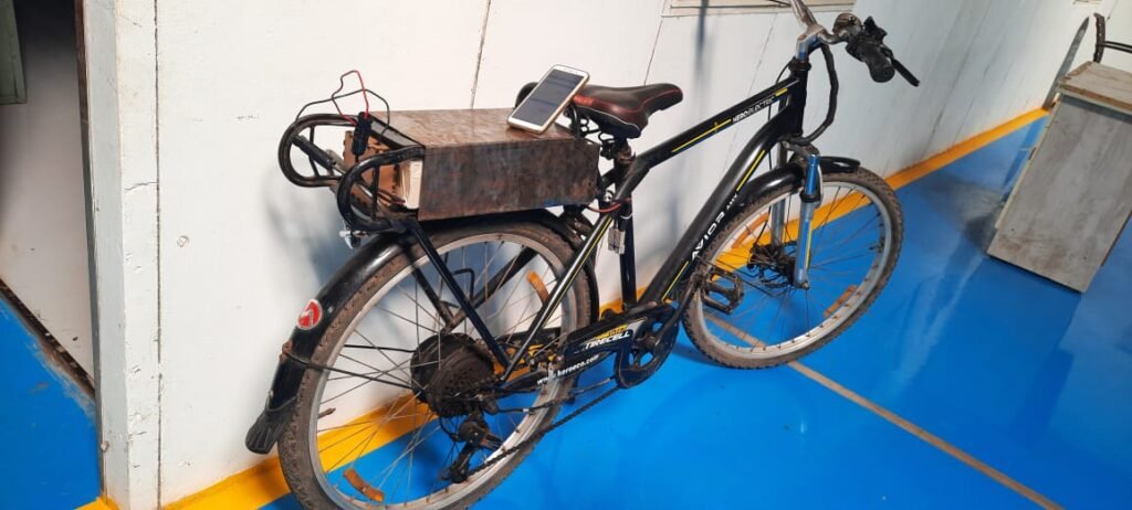
Working with Mr.Vrushabh Zunjurkar on RETROFITTING OF ELECTRICAL VEHICLE and making SMART BATTERY MONITORING SYSTEM FOR ELECTRICAL VEHICLE. Please refer to the following blogs for more information about EV.
Selection and DIY Electrical Vehicle Battery: http://vadic.vigyanashram.blog/2021/08/25/retrofitting-of-vehicles-to-e-vehicle/
Problem Statement
Date: 27th Sept 2021
Dixit Sir has an electric bike. So, he was having problems with the health of the battery of the electric bike. When he started charging the battery, he do not understand the charging percentage of the battery, but the same problem he does not want to experience with the Vrushabh -made an electrical cycle, they need an electronic device, which is shown on the battery charging and discharging percentage on mobile.
Objective
- I want to make such an electronic device that Charging and Discharging Percentage of Battery.
- An electronic device is to be made so that Vrushabh has made an electric bicycle that has a 28-volt battery, the charging and discharging percentage of that battery can be seen by the consumer on his mobile.
- Because of this Device, the health of the battery can be maintained for a long time.
- It will be easier for the consumer to use the electric bicycle.
Introduction
In this project, we will build a Battery Monitoring System For Electrical vehicles using ESP8266 and Thingspeak IoT. Using this system we can monitor battery voltage and percentage from anywhere. Therefore, this system is useful for monitoring battery Charging and Discharging status.
As we know, the battery is the most important component for any device as it powers the entire system. So, it is important to monitor the voltage level of the battery as improper or excess charging and discharging may lead to damage to the Battery or System failure.
Most of the Electrical/Electronic devices have a Battery Management System (BMS). Actually, BMS monitors all the properties of the battery like the voltage, current, temperature, and Auto cut-off system.
The BMS can only monitor the condition of the battery and alarm the user through a battery indicator, But in the System. we have used the Internet of Things (IoT) Technology which can directly notify the users remotely. The user can check the battery status on their Smartphone or Computer Dashboard from anywhere in the World
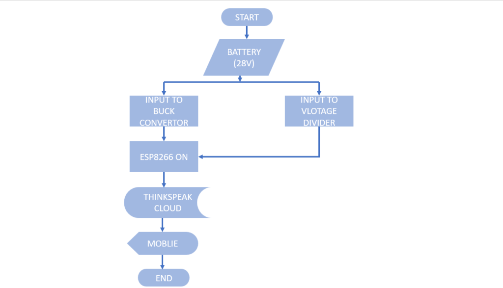
Flowchart
Working
The battery output voltage is divided into buck convertor and voltage divider circuits. The buck converter takes a high voltage from the battery and converts it into a constant 3.3 V continuously. the output voltage of the buck converter is a VIN voltage supply for ESP8266 and it helps to ON the board of NodeMCU.At that time The voltage divider circuit senses the voltage and gives the output voltage as an analog signal to the ESP8266. I upload the code on ESP8266 which helps to convert the analog data into digital form and store it on the thingspeak cloud. And with the help of the thingspeak channel users can see the charging and discharging percentage on its mobile or computer Dashboard
Components
You will need the following components for the Smart Battery Monitoring System Electrical Vehicle Project. You can purchase all the components online.
| SR.NO | COMPONENTS | DESCRIPTION | QUANTITY | LINK |
|---|---|---|---|---|
| 1 | NodeMCU or Wemos D1 Mini Board | ESP8266 ESP-12E Development Board | 01 | https://robu.in/product/nodemcu-esp8266-v3-lua-ch340-wifi-dev-board/ |
| 2 | LM2596 DC-DC Buck Converter Power Supply | Step Down Module LM2596 Switching Regulator | 01 | https://robu.in/product/lm2596s-dc-dc-buck-converter-power-supply/ |
| 3 | Resistor | 10K | 01 | https://robu.in/product/10k-ohm-0-5w-metal-film-resistor-pack-of-50/ |
| 4 | Resistor | 100K | 01 | https://robu.in/product/100k-ohm-0-25w-metal-film-resistor-pack-of-100/ |
| 5 | USB Cable | 5V Micro-USB Data Cable | 01 | https://robu.in/product/5v-3a-1-meter-micro-usb-cable-for-microbit/ |
| 6 | LCD Display | 16*2 LCD | 01 | https://robu.in/product/basic-16×2-character-lcd-white-on-blue-on-blue-5v/ |
| 7 | I2C Module | Serial I2C control of LCD display | 01 | https://robu.in/product/iici2c-serial-interface-adapter-module/ |
- Here is the description of components used in the system.
- And information regarding why I choose this component and how it actually works in the system
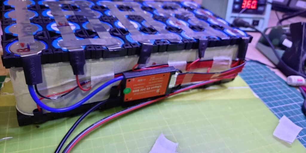
- DIY LITHIUM IRON PHOSPHATE (LIFEPO4) BATTERY:
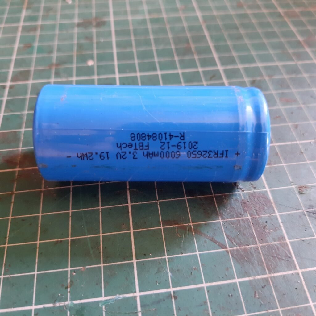
- A Lithium Iron Phosphate (LIFEPO4) Battery is a rechargeable battery. Lithium-ion batteries are widely and commonly used for portable electronic and Electric vehicles.

Cell Size:32650,Cell Model:IRF3200N60 
DIY LITHIUM-IRON PHOSPHATE BATTERY(LIFEPO4)
- Please refer to the following blogs for more information about batteries.
DIY Lithium Iron Phosphate (LIFEPO4) Battery:-DIY Lithium Iron Phosphate (LiFePO4) Battery for Electric-Cycle
2. Buck Converter:
- LM2596 is a step-down voltage regulator, also known as buck convertor.
- Its mainly used to step down the voltage or to drive load under 3A.
- LM2596 carries the remarkable load and line regulation and in fixed output voltage including 3.3V.
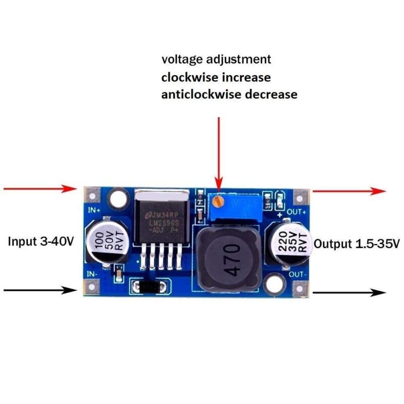
- I have converted the input voltage of the battery to 3.3 volts using lm2596.
- Lm 2596 gives me a single constant value of 3.3V for any variable voltage value from 22V to 28V.
- Using LM2596 its helps me keep up with esp8266. And my charging and discharging data helps to reach the Cloud / Thingspack’s channel.
3. Voltage Divider Network Calculation:
Date:12th Oct 2021
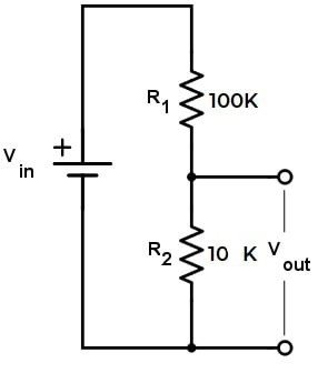
The Battery Maximum voltage is 28V and the cut-off voltage is 22V. Anything lesser than 3.3V will be easily supported by ESP8266 Analog Pin.
I have used the following link to determine the value of the resistors I was going to use in making the Voltage Divider circuit.https://www.allaboutcircuits.com/tools/voltage-divider-calculator/
- Since the analog pin of esp8266 has the same input voltage range as 3.3 V, I needed to convert the battery’s 28-22 V to 0-3.3V.
- I was going to need a Voltage sensor to convert High Voltage to Low Voltage.
- I decided to make a voltage divider circuit as I did not get 30 and range voltage sensors in the market.
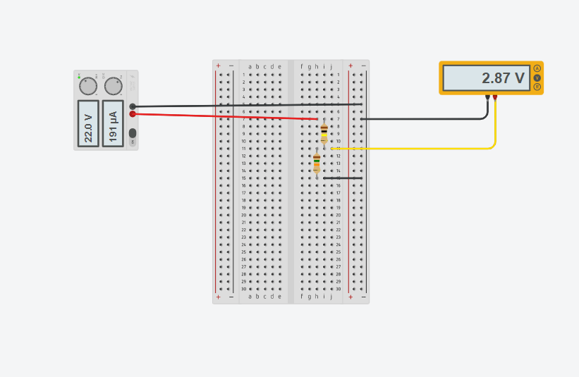
- I made this voltage circuit and calculated it by taking resistors of different values and after concluding all of them I decided to use two resistances 100k and 10k.
- The primary purpose of this curcuit is to scale down the input voltage to a lower value based on the ratio of the two resistors.
- Determine the output voltage of the divider circuit given the input voltage and the resistor values.
Equation:
Vout=Vin*R2/(R1+R2)
Where;
Vout=Output Voltage.
Vin=Input Voltage.
R1 and R2=Resistor Values.

Simulation Ckt For Voltage Divider 
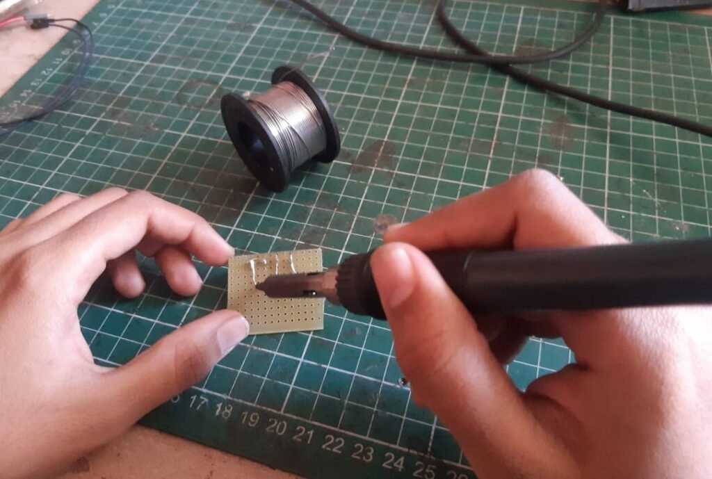
Soldering 
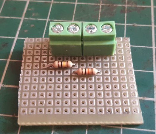
Voltage Divider Ckt
- First step down to the upper voltage level .so,to do thwt i will use a pair of 100K and 10 K resistors.
- It will convert the source voltage from 28V to 2.55V .Similarly,the cut-off voltage is also stepped down from 22V to 2V.
- Now ,both upper and lower voltage is supported by NodeMCU ESP8266 Analog Pin.
4. NodeMCU ESP8266:
- The NodeMCU ESP8266 developed board comes with the ESP-12E module containing the ESP8266 chip having Tensilica Xtensa 32-bit LX106 RISC microprocessor.
- This microprocessor supports RTOS and operates at 80 MHz to 160 MHz adjustable clock frequency.
- NodeMCU has 128 KB RAM and 4MB of flash memory to store data and programs.
- Its high processing power with in-built Wi-Fi /Bluetooth and Deep Sleep Operating features make it ideal for IoT projects
- NodeMCU can be powered using a Micro USB jack and VIN pin
- It supports UART,SPI,and I2C interface
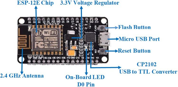
- ESP8266 is an in-built WiFi module. And since it stores data memory, it helps me build an iot based battery monitoring system.
- In ESP8266, I have created the code in the C language of coding and uploaded it with the help of Arduino IDE software.
- ESP8266 is a very important component of my system. I can display the data of battery charging and discharging percentage on the web.
Circuit Diagram
Date: 16th Oct 2021
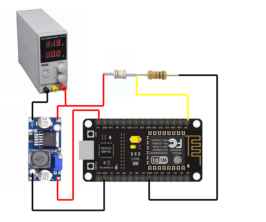
The circuit diagram for Smart Battery Monitoring System is Shown below.
Connection:
- The positive terminal of the battery is connected to the Input /positive side of the Voltage divider circuit, which Simultaneously is connected with the input terminal of the buck Convertor.
- The output of the voltage divider circuit is connected to the analog pin (A0) of ESP8266.
- The VIN pin of ESP is connected to the positive output terminal of the buck convertor which gives the continuously constant 3.3 V supply.
- The negative terminal of the battery is connected to the negative input terminal of the buck converter and the ground pin of ESP8266 is connected to the output negative terminal of the buck converter and voltage divider circuit
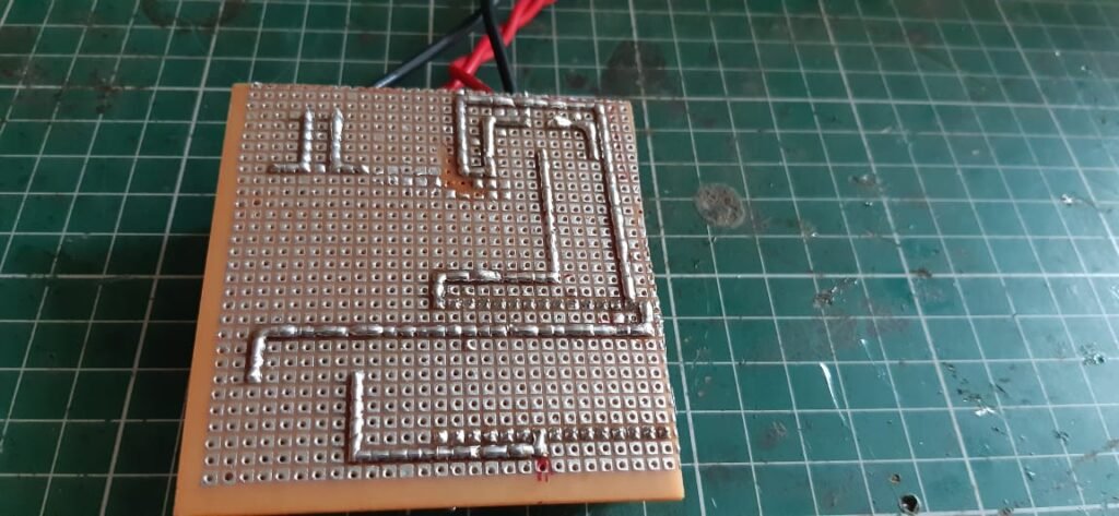
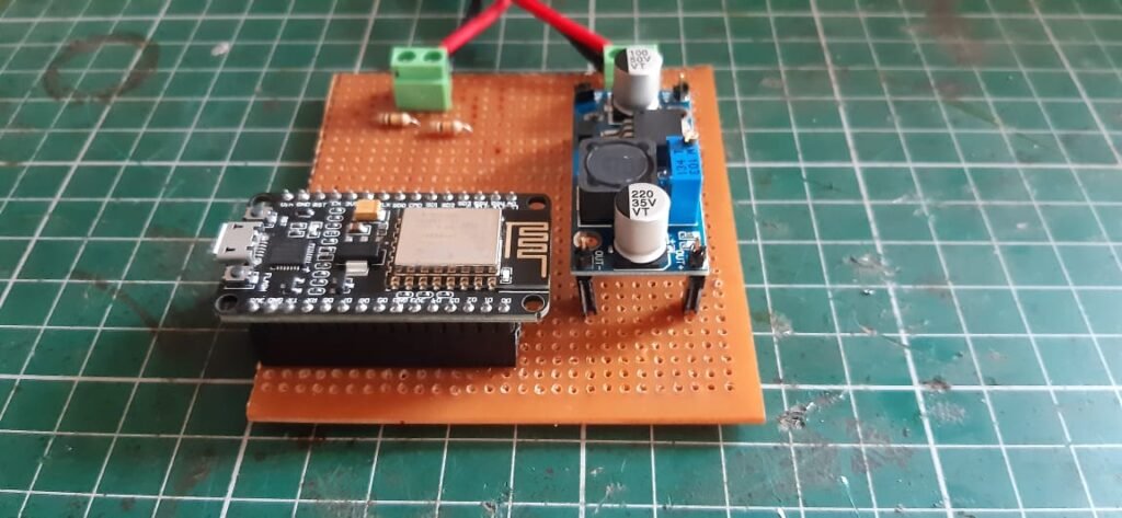
Following the instructions above, I have fixed the connection of my circuit on the PCB board as below.

Soldering 

Complete Hardwere
Programming NodeMCU ESP8266 with Arduino IDE
Date: 20th Oct 2021
- The NodeMCU Development Board can be eadily programmed with Arduino IDE Software since it is easy to uesd.
- Programming Esp8266 with the Arduino IDE will hardly take 2-3 Minutes.
- All you need the Arduino IDE Software ,a USB cable and NodeMCU ESP8266 Board .
Uploading your First Program:
- Once Arduino IDE is installed on the computer,connect the board with the computer using the Usb Cable.
- So to do this ,open Arduino IDE and go to the File>Preferences.

Then a new window will pop up in which add the below link in ” Additional Board Manager URL’s ” and click.
“OK”.http://arduino.esp8266.com/stable/package_esp8266com_index.json
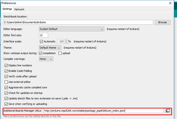
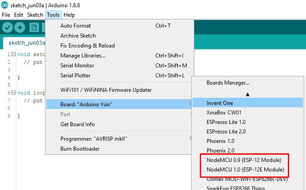
- Now in your Arduino IDE go to Tools>Board>Boards Manager.
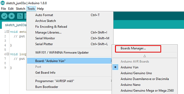
- And search for “ESP8266”, then install “ESP8266 by ESP8266 Community” package by clicking on “Install” button .(I already installed the board that is why the install button is disabled)
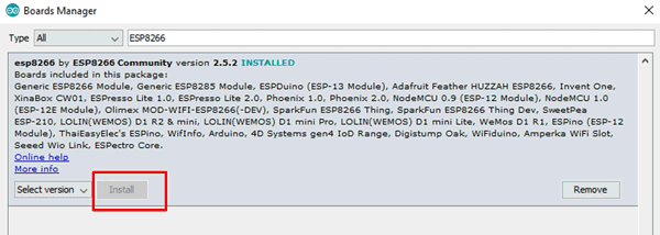
- It will take a couple of minutes to complete the installation.
- Once the installation is complete you will be able to see NodeMCU in your boards list.
Source Code:
- Here is the source code for the Smart Battery Monitoring System using ESP8266.
- Replace the WiFi SSID,Password and API Key in the code.

- Now open the Arduino IDE and choose the correct board by selecting Tools>Boards>NodeMCU ESP8266 and choose the correct port by selecting Tools>Port.
- Copy the follwing Code and upload it to your NodeMCU ESP8266.
Create Thingspeak Account
Date:20th Nov 2021
ThingSpeak provides a very good tool for IoT-based projects. By using the Thingspeak site, we can monitor our data and control our system over the Internet, using the channel and webpages provided by Thingspaek.
- In order to Monitor the Battery Data on Thingspeak Server, you first need to set up the Thingspeak.
- To set up the Thingspeak Server, visit https://thingspeak.com/.
- Create an account or Simply sign in if you created the account earlier.
- Then create a new channel with follwing details.
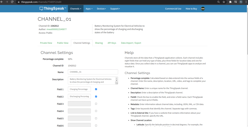
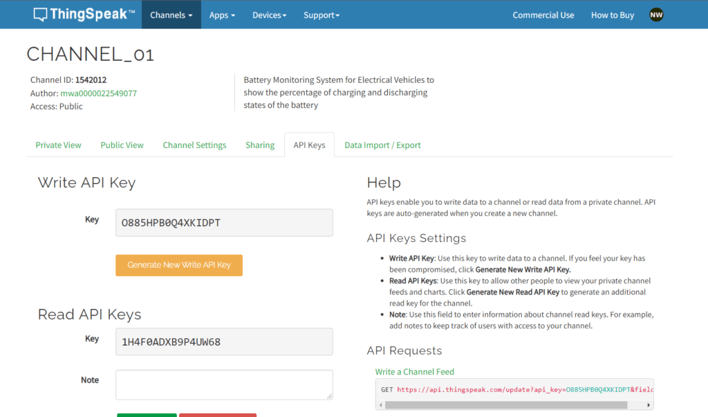
- Then go to the API Keys section of the dashboard and copy the API key is needed in the code part.
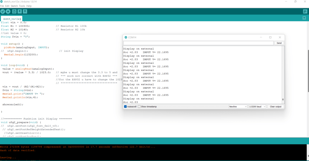
- Open the Serial Monitor after uploding the code.
- The ESP8266 will try connecting to the wifi network.
- Once it connects to the WiFi Network,it will display the Analog Value anong with Battery Voltage & Percentage.
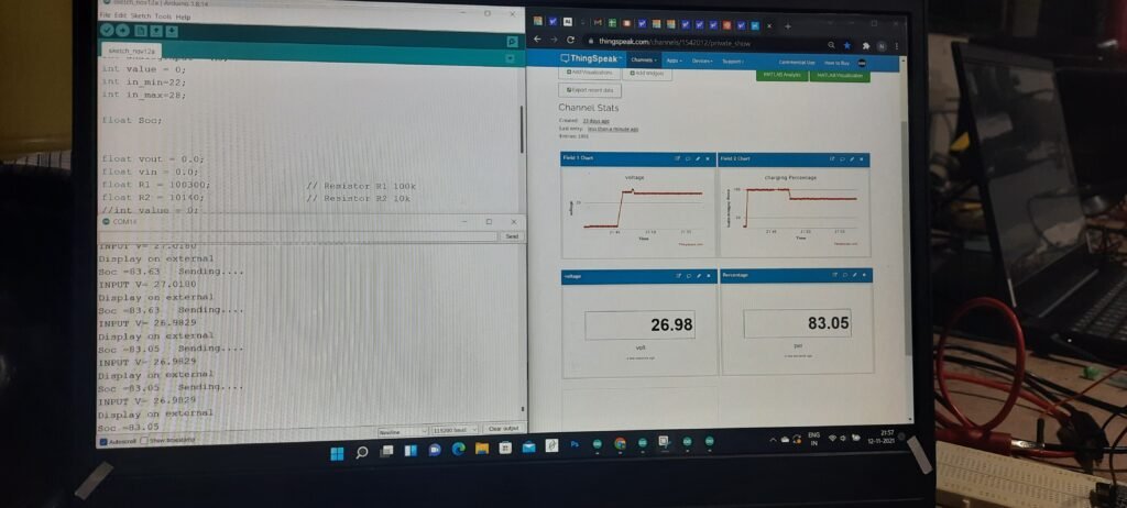
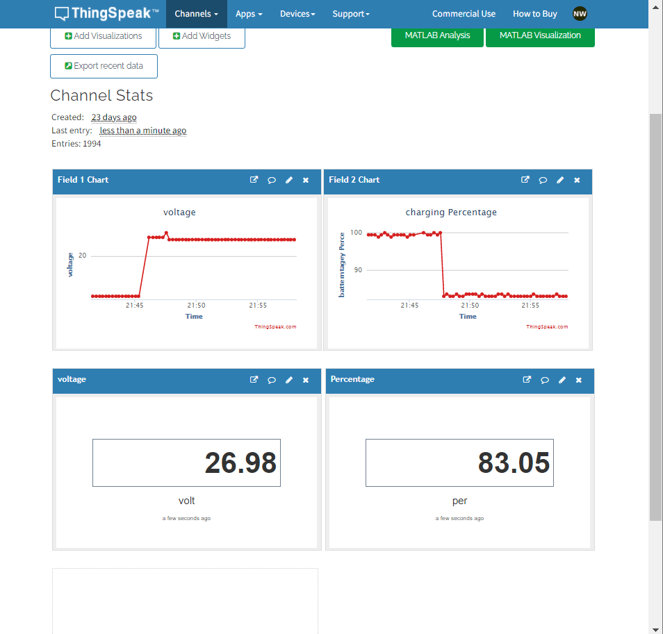
- Then go to the private view of Thingspeak Dashboard.
- The Battery Voltage and Battery Percentage will fill the graph.
- the graph will rise up when the device is Charging and will go down when it’s Discharging.
Testing
Date: 22nd Nov 2021
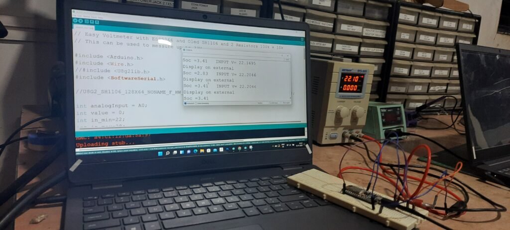
So this is how we can design Smart Battery Monitoring System using ESP8266 and get the Reading on Thingspeak Server.
1st Trial:
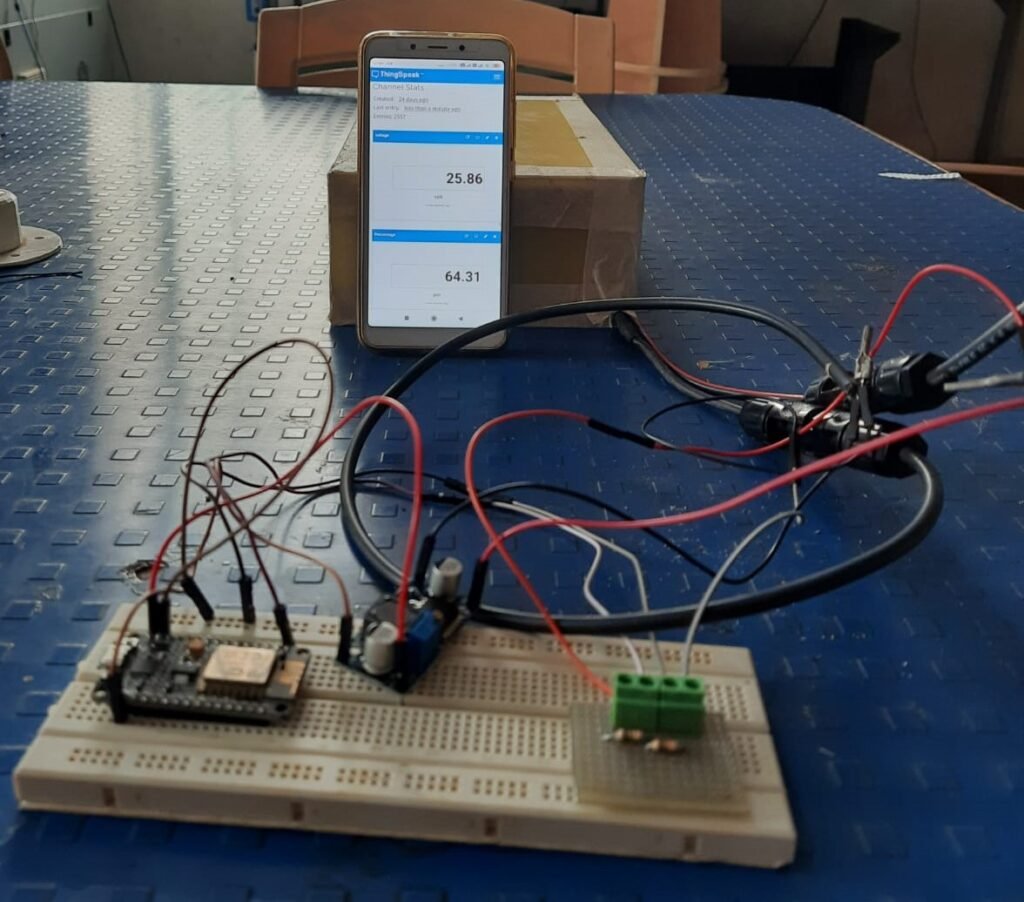
2nd Trial:
Satisfy results were gets on the basis of given trials.
Our Smart Battery monitoring System Shows the battery Charging and Discharge percentage on mobile /Dashboard.
Develope App Using MIT APP INVENTOR
Date: 28th-Nov to 11 Dec 2021
- After several such trials, I realized that the developer was having difficulty checking the battery percentage by going to Thingspeck channel.
- Decided to create a user friendly app to make it easier to check the battery percentage.
- I have used this open source server on MIT App Inventor to make app.Visit,https://appinventor.mit.edu/
- After visiting this link, I signed in with the help of Google Account.
- The first page of MIT App Inventor opened as follows:

- After that I started making app by clicking on Create Apps! button.
- After clicking the start with new project button, the page opened and it looked like the following
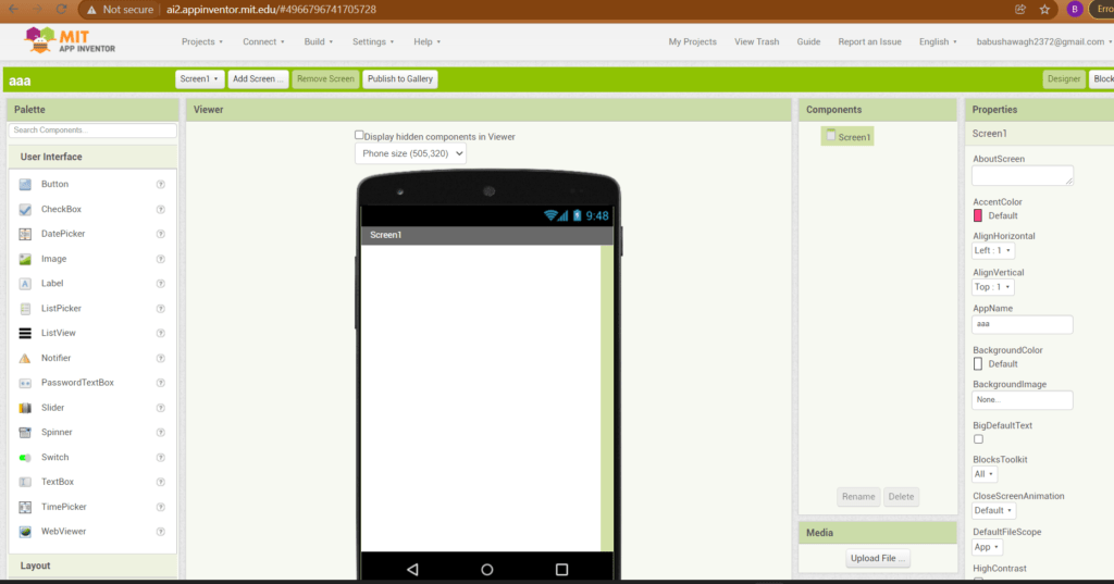
- On this page you can arrange how the mobile screen should look after opening your app.
- A new window will open showing various layout items such as buttons, sliders and text boxes.
- I have made this led controller app only to check if App and Thingspeak channels communicate with each other and show the same data.
- Initially I decided to make an app to turn ON/OFF a led. And for that I took two buttons and one web and designed it as follows.

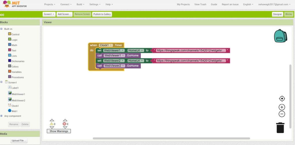
- After designing, I clicked on the block button and did the block coding for the app. For this, I created a channel of Thingspeak and used its link here.
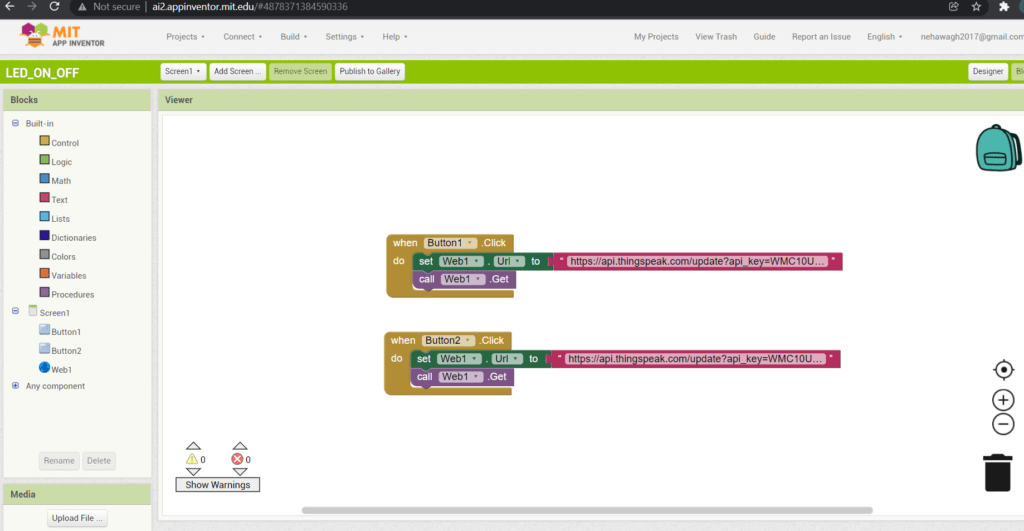
- Then I click on the “Build” app tab and install the .apk file in my Android.
- After installing the .apk file, I uploaded the code in ESP and LED Controller.
- The led controller App I wanted to make using MIT app have been completed and data is being collected on Thingspack channel.
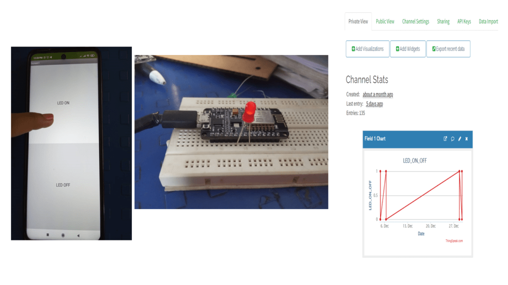
The LED controller App I created and the Thingspeak channel are communicating with each other.
- From this experience I started trying to show battery percentage and voltage data on Thingspeck channel and MIT app.
- These are the steps that have been taken while designing the above App.
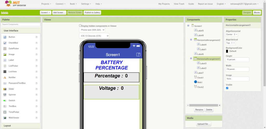
- Using the steps above, I have coded and designed the block screen for my system app screen as given below and used the Thingspeak channel link for voltage and percentage.
- After this I downloaded a file of the app I made and installed it in my Android mobile and I got the following output in which I could only see the value of Voltage and Percentage.After some time the error started appearing on the mobile screen. then I took the help of Mr. Rahul
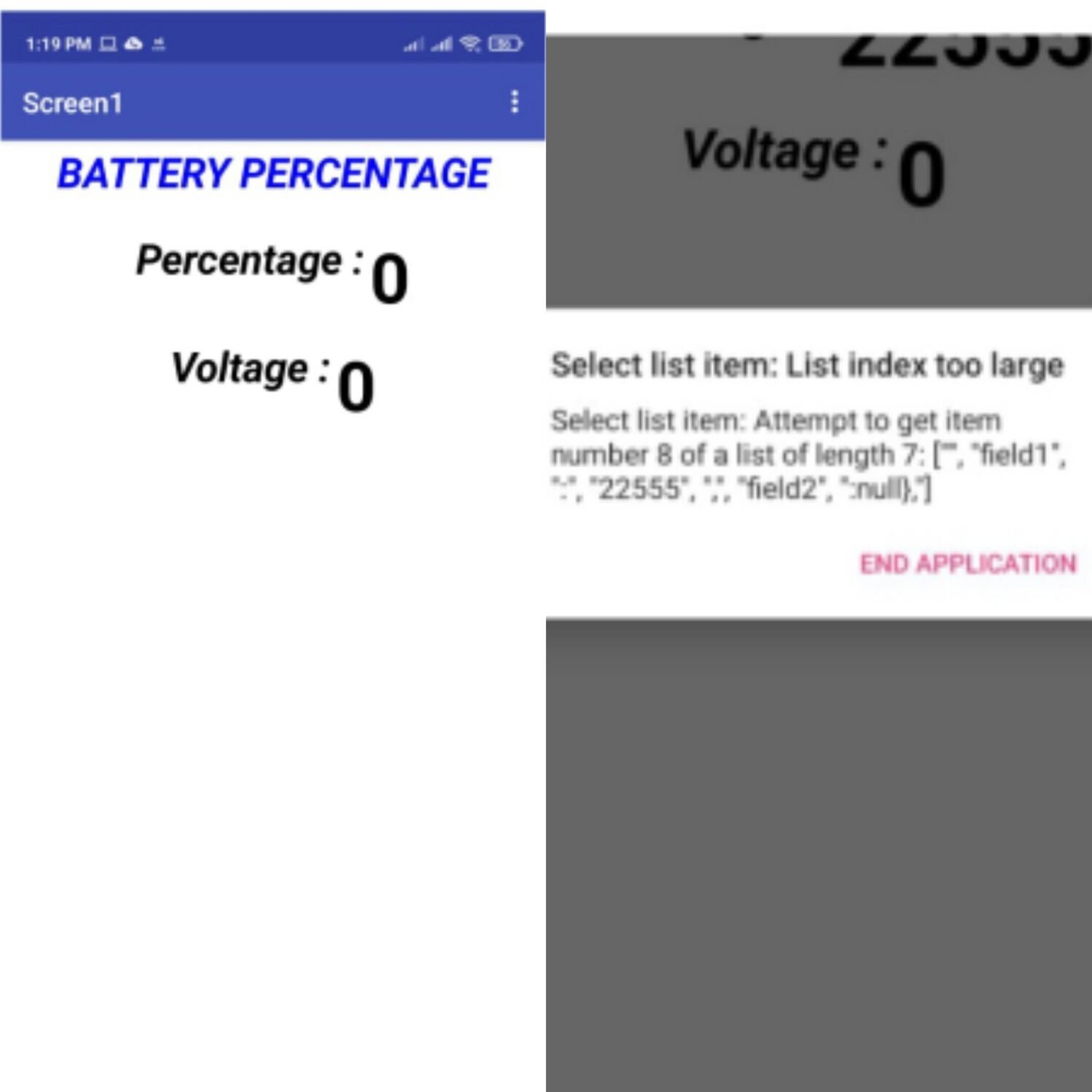
- I found that I did not understand the time before the data entry of voltage and percentage, so I should understand the last data entry time, so I linked the channel and app by linking to the channel webpage.
- After that I designed a new screen and did block coding and made a new app on which I could see the last data entry time, voltage and percentage.
- I think it will be easier for the user to handle the newly created app after downloading the .apk file of that app and installing it in the mobile.
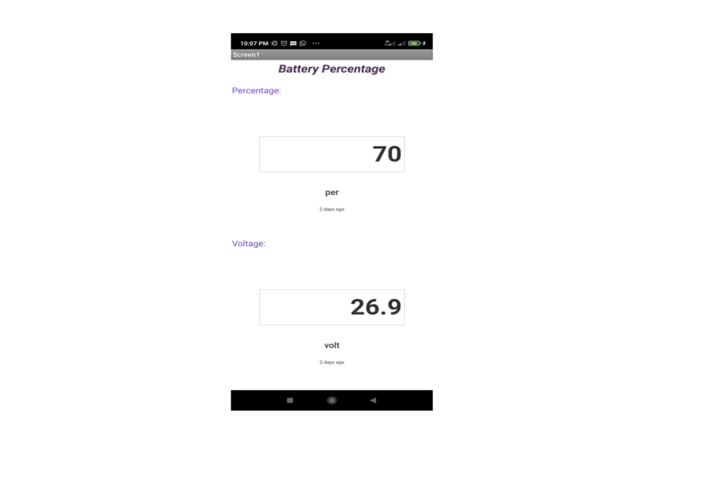
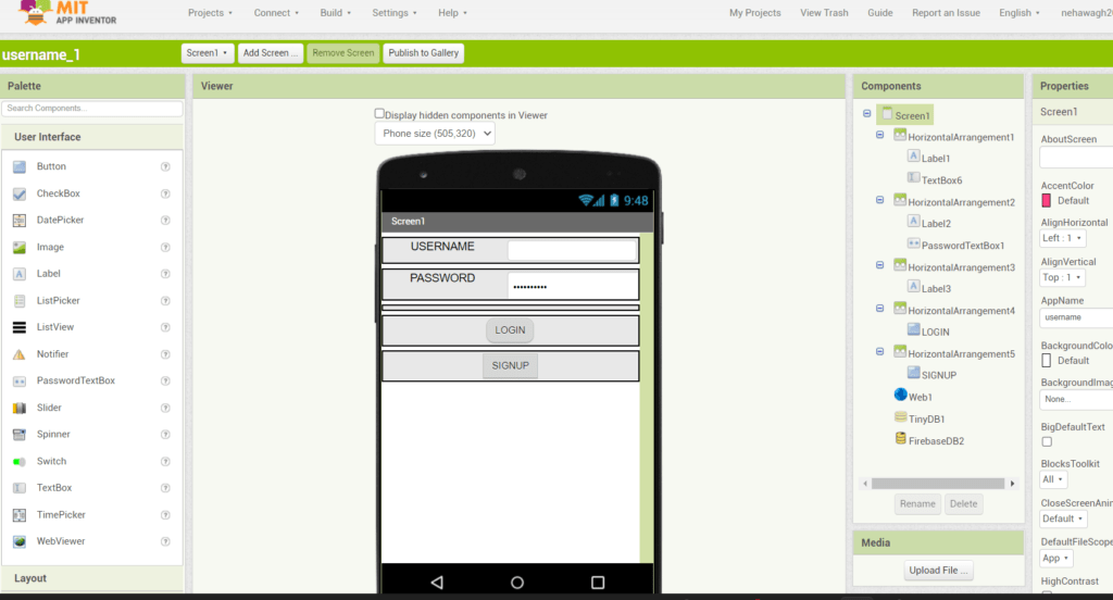
One of the problems I encountered when I started trial was that whenever the app user was changing, I had to change the SSID and password to code and upload the program.
And then it was realized that you need to get access for SSID and password from the user
So I went back to the screen design of the app and did the block coding.
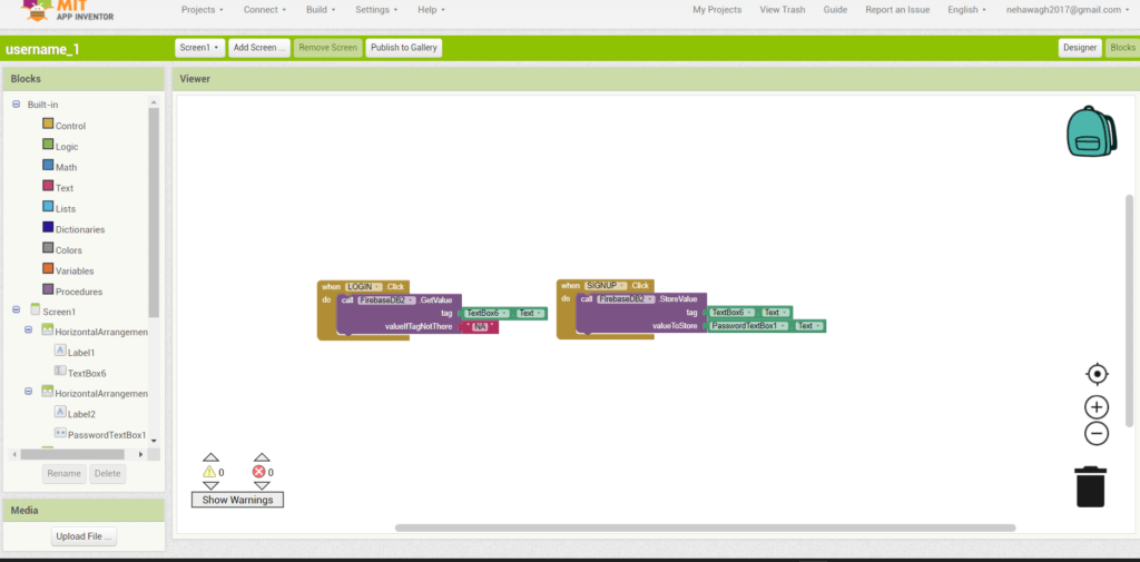
- But for that, data had to be stored. The following link is the basis for how to store it. https://www.geeksforgeeks.org/how-to-make-a-login-and-sign-up-application-in-mit-app-inventor-using-firebase/
- After following all the steps in the link, we did not get the desired result.
- After this I discussed this problem with Rahul and from that I realized that node MCU does not connect easily with any other network.
- So we decided that by fixing a password and user name (SSID) for this, each user should set the hotspot name and password of their mobile phone as given below and do the same.
Username(SSID):- Password
Password:-12345678
Display Monitoring System
Date:20th-25th Dec 2021
- The easiest way to display the voltage and battery percentage on the LCD screen and the user will not have much difficulty in using the electrical cycle.
- Then I decided to make a monitoring system using 16 * 2 LCD display and I2C module that easily interfaces with Thingspeak channels or app.
- For this I have connected LCD and I2C modules with ESP.
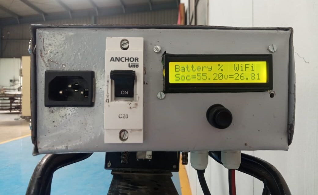
- After this I have connected with a switch and charging plug battery. You can see the connection I made in the diagram below:
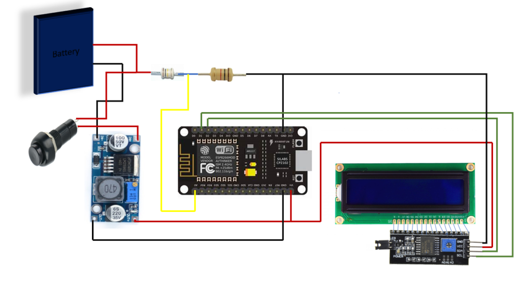
- Coded for ESP to display voltage and percentage on lcd screen
- This code was uploaded to esp and took trials
- After making this connection with the battery, the front view of the battery looked like this.
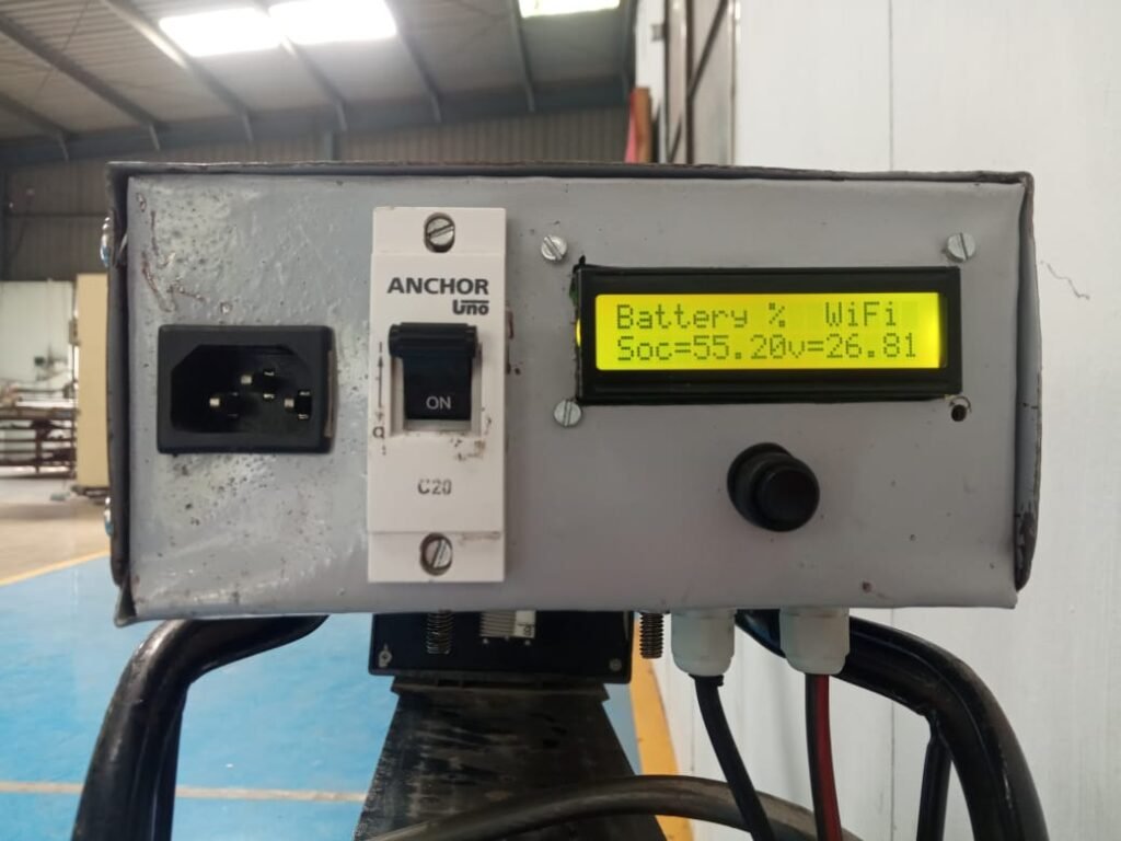
- After the LCD display was done I programmed for Thingspeak channel, App and display.
- After this we took some trials and from that we realized that percentage of battery is not visible properly, discharge occurs in 15 to 20 minutes after battery is 50%.
- We discussed this problem with Dixit Sir. After that we decided to charge and discharge the battery again and Data collected it.
- After discharging the battery no load condition, 5 minutes readings were collected.
- The following is the data of discharging state.
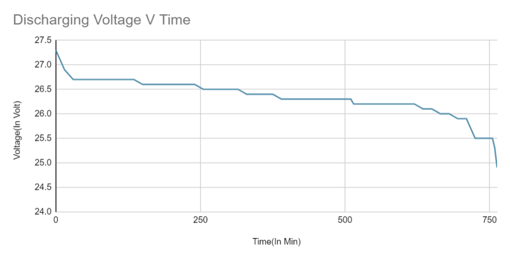
- After this, I take a Reading at Charging Condition and collect data after 15 Min.
After this, I have collected the data for charging and plotted the graph accordingly.

Date:27thDec 2021
- I observed both the graphs above and from that I realized that it takes 4 hours to charge the battery and 14 hours to discharge.
Calculation :
We know,
Q=I*t ………..(1)
Where,
Q=Charge Store in Battery
I=Current (24A/hrs.)
t=Time(hrs.)
From equation 1
Q=24*60*60
………(given in the battery specification)
Q=86,400C
………(Total Charge capacity of battery)
Without BMS voltage range of the battery is 22V-28V.
With BMS voltage range of the battery is 24.9V-27.3V. Here it is understood that the BMS connection changes the battery voltage range.
Then, I consider
Q=80,000C
……….(charge capacity of Battery With BMS)
- For Charging :-
It takes about 4 hours for the battery to charge
We evenly divided the charge
When the battery charger was connected to the MSCB meter for charging, a 6-watt power battery was consumed.
t=6
Q=80,000C
we find: Q1=?
Q1 = 80000/6
Q1 = 13,333.33 C
So for every watt, we took a reading of Voltage
- For Discharging :-
It takes about 14 hours for the battery to discharge
We evenly divided the charge
The battery was in no-load condition while discharging
t=14
Q=80,000C
we find: Q2=?
Q2 = 80000/14
Q2 = 5714.28 C
So for every hour, we took a reading of Voltage
The following data was collected for both the above states.
After that, the graph plotted according to the above data is as follows.
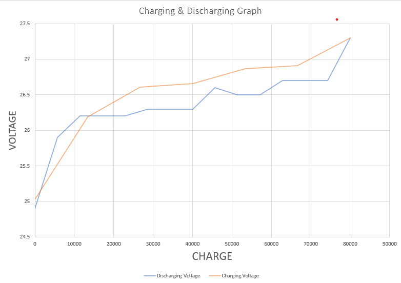
We determined the voltage range by observing the graphs above.
i.e., Cutoff Voltage =26.2 V and Fullcharge Voltage=27.3V
Estimate the percentage value by inserting it in the above value code.
Copy the following code and upload it to your NodeMCU ESP8266.
PCB Design
I have designed Zero PCB according to the circuit diagram.

Casing
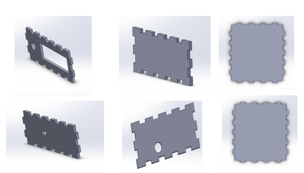
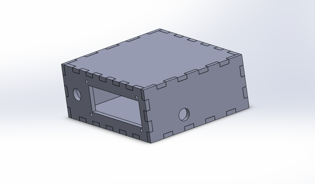
Designed a box for the casing on SolidWorks software and cut it on a 4 mm acrylic sheet with the help of a laser cutting machine, and joined the box.
Cad Model:
Instructable For Smart Battery Monitoring System
The following instructable should be used when using the system.
- Note:
- As battery voltage fluctuates in steady condition also, this results in fluctuation of readings displayed on the LCD.
- The battery monitoring system is designed for 24 V DIY LiFePo4 battery pack only.
- The Node MCU does not connect easily with any other network.
- So we decided that by fixing a password and user name (SSID) for this, each user should set the hotspot name and password of their mobile phone.

