Introduction
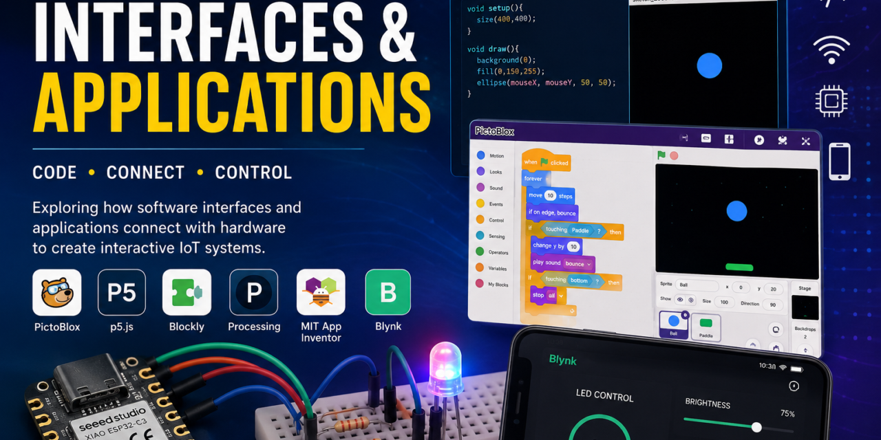
In Week 6, I explored Interfaces and Applications and learned how different software platforms can be used to create interactive applications and communicate with electronic systems. The main focus of this week was understanding the connection between hardware and software and how interfaces can be used to control devices, display information, and interact with users.
During this week, I worked with several tools and platforms, including Processing, p5.js, Blockly, PictoBlox, MIT App Inventor, and Blynk. I created games using block coding in PictoBlox, installed and explored Processing, experimented with p5.js, controlled LED using the XIAO ESP32-C3, and displayed data through a web server.
I also explored mobile-based IoT applications using MIT App Inventor and Blynk. Using Blynk, I created a mobile interface to control an LED . These activities helped me understand how microcontrollers, sensors, computers, web interfaces, and mobile appliations can work together to create interactive and useful IoT systems.
What are Interfaces & Applications
An interface is a medium through which a user, software, or electronic device communicates with another system. It allows users to control devices, send commands, and view information in an easy-to-understand form. Examples of interfaces include mobile applications, web pages, graphical user interfaces, buttons, displays, and dashboards. An application is a software program designed to perform a specific task or solve a particular problem. In embedded systems and IoT, applications can be used to monitor sensor data, control devices, and communicate with microcontrollers. During this week, I learned about interfaces and applications using Processing, p5.js, Blockly, PictoBlox, MIT App Inventor, and Blynk, and understood how they can be connected with hardware such as the XIAO ESP32-C3, LEDs.
Interfaces I Use:-
1. Pictoblox
PictoBlox is a block-based programming software that helps beginners learn coding in an easy and visual way. Instead of writing complex code, users can drag and connect blocks to create programs, animations, games, and interactive projects. It can also be used to control hardware such as microcontrollers, LEDs, sensors, and robots. In my Week 6 work, I used PictoBlox to create games using block coding, which helped me understand basic programming concepts such as events, conditions, loops, and actions.

Installation of Pictoblox
1. I searched pictoblox download for winodws on google

2. Downloaded Pictoblox

Ball Bounce on Paddle – PictoBlox
I created a Ball Bounce on Paddle game in PictoBlox using block coding.
1.Opened PictoBlox and clicked on Blocks

2. Pictoblox interface

3. Added a ball sprite and paddle sprite to the stage.

4.Set Backdrop

5. Programmed the ball to move continuously across the stage in 45 degree.

6. Programmed the paddle to move left and right using the keyboard arrow keys.Added blocks to make the ball bounce when it touches the edges of the stage. When the ball touches the paddle, I made it bounce back upward and If the ball touches the bottom, I made the game stop.

7.Finally, I tested the game and adjusted the movement of the ball and paddle to make the game work properly.

Hand Gesture Game – Pictoblox
I created a hand gesture-controlled game using PictoBlox. I used hand movements as inputs to control the game, which made the game interactive and fun. This activity helped me understand how gesture recognition and block-based coding can be used together to create an interactive game.


Processing
Processing is a coding tool that helps us create animations, games, graphics, and interactive projects. It is easy to use and helps us understand programming by showing the output visually. We can also use it with hardware to perform tasks like turning an LED ON and OFF.

1. I opened a web browser and searched for the Processing official website.

2. I went to the download section

3. Selected the version compatible with my computer. I downloaded the Processing setup file. I

4. Opened the downloaded file and started the installation. I followed the instructions and completed the installation. After installation, I opened the Processing application.

5. Processing interface

RGB LED Control Using ESP32-C3, Processing and Arduino IDE
I connected the RGB LED to the ESP32-C3 board using the required connections. I then used the Arduino IDE to write and upload the code for controlling the LED.

After that, I used Processing to create an interface and communicate with the ESP32-C3. By running the code, I was able to send commands from Processing to the ESP32-C3 and control the RGB LED.

This activity helped me understand how Processing, Arduino IDE, ESP32-C3, and hardware can work together to control an LED.


Servo Motor Control Using ESP32-C3, Processing and Arduino IDE
I first connected the servo motor to the ESP32-C3 board and uploaded the required code using the Arduino IDE.

Then, I wrote and ran the code in Processing and created a slider to control the servo motor. When I moved the slider to different positions, the servo motor also moved to the corresponding angle.


Webserver
A web server is a system that receives requests from a web browser and provides information or controls through a web page. In my project, I used a web server to create a simple webpage with controls that allowed me to turn an LED ON and OFF using the ESP32.
RGB LED Control Using ESP32-C3
First, I connected the RGB LED to the ESP32-C3 board. Then, I wrote the Web Server code in Arduino IDE and entered my Wi-Fi SSID and password in the code. I uploaded the code to the ESP32-C3 and connected it to the Wi-Fi network.

After connecting to Wi-Fi, I checked the IP address of the ESP32-C3 and entered that IP address in a web browser. This opened the RGB LED control webpage, where I could adjust the Red, Green, and Blue values using sliders.

By changing the slider values, I was able to control the colour and brightness of the RGB LED.By changing the values through the web interface, I was able to control the colour and brightness of the RGB LED wirelessly.


Webserver interface on mobile

Servo Motor Control Using ESP32-C3
I followed the same process for the servo motor. First, I connected the servo motor to the ESP32-C3 and uploaded the Web Server code using Arduino IDE. I entered my Wi-Fi SSID and password in the code and uploaded it to the board.

After connecting to Wi-Fi, I checked the IP address of the ESP32-C3 and entered it in a web browser. The web page provided a slider to control the servo motor angle. When I moved the slider, the servo motor moved to the corresponding position.

Webserver interface on mobile

P5.Js Web Editor

p5.js is a JavaScript library used to create animations, graphics, games, and interactive web projects. It allows us to write code in the p5.js Web Editor and see the output directly in the browser. In my project, I used p5.js to create animations and simple games and understand how coding can be used to make interactive visuals.
1. I opened the p5.js Web Editor and wrote and uploaded the required code.

2. p5.js is a JavaScript library used to create interactive graphics, animations, and games. After running the code, I created animations and simple games and observed how the output changed according to the code. This activity helped me understand the basics of JavaScript and creative coding.


Blockly

Blockly is a visual programming tool that uses drag-and-drop blocks instead of writing code manually. It helps beginners understand programming concepts such as loops, conditions, and logic in a simple way. I used Blockly Games to practice coding and understand basic programming logic through interactive games.
1. I searched for Blockly and explored Blockly Games to understand the basics of coding.

2. I played different games where I had to arrange and connect coding blocks to complete tasks. This helped me understand programming concepts and logic in a simple and interactive way. It also gave me a basic understanding of block-based coding without having to write the code manually.

3. Blockly Games Interface


IOT Applications
IoT applications are applications where physical devices are connected to the internet and controlled or monitored using software or mobile apps. In my work, I used MIT App Inventor to develop an app for controlling an LED and Blynk to control an LED, RGB LED, and servo motor. This helped me understand how software, internet connectivity, and hardware can work together.
MIT App Inventor (Blinking of LED)

As part of my individual assignment, I developed a mobile application using MIT App Inventor to control an LED over Wi-Fi. I designed a user interface with ON and OFF buttons and connected the application to the ESP32 wroom. When I pressed the buttons, the application sent commands over the Wi-Fi network, and the LED turned on or off accordingly. I tested the application successfully and confirmed that the LED responded correctly to the command.

1. I opened MIT App Inventor and designed the mobile application interface by adding ON and OFF buttons.

2. I wrote the program for the ESP32-WROOM in the Arduino IDE to control the LED through Wi-Fi. I entered my Wi-Fi credentials (Wi-Fi name and password) in the program so that the ESP32-WROOM could connect to the Wi-Fi network. I uploaded the program to the ESP32-WROOM using the Arduino IDE. After the ESP32-WROOM connected to the Wi-Fi network, I opened the Serial Monitor and copied the IP address assigned to the ESP32.

3. I returned to MIT App Inventor and completed the Blocks coding by entering the ESP32 wroom IP address so that the application could communicate with the ESP32.

4. I returned to MIT App Inventor and completed the Blocks coding by entering the ESP32 IP address so that the application could communicate with the ESP32.Saved the project and generated a QR code in MIT App Inventor. I scanned the QR code using my mobile phone and installed the application.


5. I opened the application on my mobile phone and ensured that the phone was connected to the same Wi-Fi network as the ESP32-WROOM. Finally, I pressed the ON and OFF buttons in the application to turn the LED on and off, verifying that the communication between the mobile application and the ESP32-WROOM was successful.


Blynk App Developer

Blynk is an IoT platform used to connect and control hardware devices through a mobile app or web interface. It allows users to create dashboards with buttons, sliders, and other controls to operate devices such as LEDs, RGB LEDs, and servo motors. In simple words, Blynk helps us control hardware using an app through the internet.
1. Searched Blynk on google

2. Signed up on Blynk

3. Blynk interface

IoT-Based Control of LED Using Blynk
1. First, I Created New Template in Blynk with name ESP32 LED

2. Then, I created a Datastream by selecting New Datastream

3. Configured the required datastream interface.

4. Datastream interface

5. I created the Dashboard

6. Added a Button widget for LED control

7. I configured the button for ON/OFF control and saved the settings

8. Next, I created a New Device

9. Selected the template I had created.

10. I selected ESP32 as the hardware and gave the device a name related to the LED.The device dashboard showed the LED ON/OFF button.

11. Installed the ESP32 by Espressif Systems board package.Then selected XIAO ESP32-C3 and the correct COM port.I connected the LED to D9 through a resistor.I uploaded a simple blink program to test the LED.Then I installed the Blynk library in Arduino IDE,entered the Wi-Fi details and Blynk credentials in the code. uploaded the Blynk program to the XIAO ESP32-C3.The ESP32 connected to Wi-Fi and Blynk Cloud.


Code
#defineBLYNK_TEMPLATE_ID "TMPL3U73excWI"#defineBLYNK_TEMPLATE_NAME "ESP32 LED"#defineBLYNK_AUTH_TOKEN "kWbOy5fLdN0E-_ahP1_sRBu72e9J4bDi"#include<WiFi.h>#include<BlynkSimpleEsp32.h>charssid[] = "OnePlus";charpass[] = "asdfghjkl";#defineLED_PIN D9BLYNK_WRITE(V0){intvalue = param.asInt();digitalWrite(LED_PIN,value);}voidsetup(){Serial.begin(115200);pinMode(LED_PIN,OUTPUT);digitalWrite(LED_PIN,LOW);Blynk.begin(BLYNK_AUTH_TOKEN,ssid,pass);}voidloop(){Blynk.run();}
IoT-Based Control of RGB LED Using Blynk
Did same for RGB Led,
Added a Button widget for RGB LED control then I configured the button for ON/OFF control and saved the settings.


Then, I created a Datastream by selecting New Datastream & Configured the required datastream interface.


Created New Device

RGB Led Interface

Uploaded code through Arduino IDE to Xiao ESP32-C3 to Blink RGB LED

Code
#defineBLYNK_TEMPLATE_ID "TMPL3kbHPqOHY"#defineBLYNK_TEMPLATE_NAME "RGB led"#defineBLYNK_AUTH_TOKEN "2N3xel0n18CuOs8aimlk6JKNUJbkG-kq"#include<WiFi.h>#include<BlynkSimpleEsp32.h>charssid[] = "Xiaomi";charpass[] = "123456789";// RGB pins#defineRED_PIN 21#defineGREEN_PIN 8#defineBLUE_PIN 9boolredState = false;boolgreenState = false;boolblueState = false;// Update RGB LEDvoidupdateRGB(){digitalWrite(RED_PIN,redState ? HIGH : LOW);digitalWrite(GREEN_PIN,greenState ? HIGH : LOW);digitalWrite(BLUE_PIN,blueState ? HIGH : LOW);}// Red button - V0BLYNK_WRITE(V0){redState = param.asInt();updateRGB();}// Green button - V1BLYNK_WRITE(V1){greenState = param.asInt();updateRGB();}// Blue button - V2BLYNK_WRITE(V2){blueState = param.asInt();updateRGB();}voidsetup(){Serial.begin(115200);pinMode(RED_PIN,OUTPUT);pinMode(GREEN_PIN,OUTPUT);pinMode(BLUE_PIN,OUTPUT);// Start OFFredState = false;greenState = false;blueState = false;updateRGB();Blynk.begin(BLYNK_AUTH_TOKEN,ssid,pass);}voidloop(){Blynk.run();}
r


Mobile Interafce

IoT-Based Control of Servo Motor Using Blynk

l

;

l


Summary
Overall, Week 6 gave me a better understanding of how interfaces act as a bridge between users, software, and hardware. Through different hands-on activities, I learned how software can be used to send commands to hardware, receive sensor data, and present information in a user-friendly way.
Working with Processing and p5.js helped me explore interactive applications, while Blockly and PictoBlox introduced me to visual and block-based programming. Using the XIAO ESP32-C3, LEDs, and DHT22 sensor helped me understand hardware control and sensor data collection. I also learned how Blynk and MIT App Inventor can be used to create mobile interfaces for IoT applications.
This week was useful in developing my understanding of interactive systems, IoT communication, and user interfaces, and it showed me how different technologies can be combined to build practical and engaging applications.