Introduction
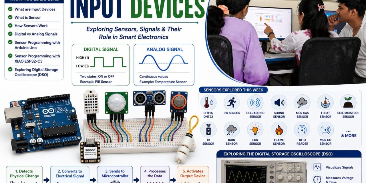
This week, I learned about Input Devices in the Fab Opportunity Academy. The main goal of this assignment was to understand what input devices are, learn about different types of sensors, and see how they work in electronic circuits.
During this week, I learned about different sensors and their uses. I understood the difference between analog and digital sensors, the types of signals they give, the purpose of signal pins, and the basic structure of sensors. I also learned how sensors send data to a microcontroller and how they are used to collect information from the surrounding environment
What are Input Devices
An input device is a component that sends information or signals to a computer or microcontroller, allowing it to detect and understand what is happening in the surrounding environment. These devices sense physical changes such as light, temperature, sound, distance, or motion and convert them into electrical signals. The microcontroller reads and processes these signals to perform a specific task or action. In simple terms, an input device is a component that provides data or information to the system.

What is Sensor
A sensor is an electronic device that detects or measures a physical change in the environment and converts it into an electrical signal that a microcontroller can process. Sensors allow electronic systems to monitor conditions such as temperature, light, sound, motion, gas, distance, and humidity, enabling the system to respond automatically.
How Sensors Work
- Detects a Physical Change
The sensor detects a physical condition such as temperature, sound, motion, gas, light, distance, or moisture. - Converts the Change into an Electrical Signal
The sensor converts the detected physical change into an analog or digital electrical signal. - Sends the Signal to the Microcontroller
The electrical signal is sent through the sensor’s output pin to the microcontroller (e.g., Arduino). - Microcontroller Processes the Data
The microcontroller reads the signal, compares it with the programmed instructions, and decides what action to take. - Activates an Output Device
Based on the processed data, the microcontroller controls an output device such as an LED, buzzer, or fan.

Digital Signal vs. Analog Signal
Analog and digital signals are two ways that sensors send information to a microcontroller.
Analog Signal
An analog signal is a signal that can have many different values depending on what the sensor detects. The value changes continuously.Like, water tap when open it a little, halfway, or fully. The water flow can have many levels.
Examples:
- Temperature sensor
- Soil moisture sensor
Digital Signal
A digital signal is a signal that has only two states: ON (HIGH/1) or OFF (LOW/0). It tells the microcontroller whether something is detected or not.Like, light switch. It is either ON or OFF.
- HIGH (1) = ON (usually 5V or 3.3V)
- LOW (0) = OFF (0V)
Examples:
- PIR motion sensor (The PIR sensor detects heat changes, processes them inside, and sends only ON (HIGH) or OFF (LOW) to the microcontroller.)
Sensors Learned This Week
This week, I explored various types of sensors used in electronics and Arduino projects. I learned how different sensors detect changes in the environment and send signals to a microcontroller for processing. I explored how sensors are connected to a microcontroller and how the processed data is used to control output devices and perform specific actions. The sensors I studied include the PIR sensor, DHT11, DHT22, sound sensor, ultrasonic sensor, RFID sensor, MQ-2 gas sensor, MQ-7 carbon monoxide sensor, float sensor, soil moisture sensor, IR sensor, and rain drop sensor. I also learned the difference between analog and digital signals and how sensors use these signals to communicate with a microcontroller. This helped me understand how sensors are used in real-world applications such as home automation, security systems, environmental monitoring, and smart agriculture.

Soil Moisture Sensor Datasheet
Individual Assignment
Sensor Programming With Arduino Uno Board
1. DHT11 Sensor
The DHT11 is a digital temperature and humidity sensor used to measure the surrounding temperature and relative humidity. It contains a humidity sensing component, a temperature sensor, and an internal microcontroller that converts the measured values into digital signals. The DHT11 is easy to interface with an Arduino Uno and is commonly used in weather monitoring, smart home systems, and environmental monitoring projects.

DHT11 Programming
In this experiment, I connected the DHT11 temperature and humidity sensor to the Arduino Uno to measure the surrounding environmental conditions. The VCC pin of the sensor was connected to the 5V supply, the GND pin to ground, and the DATA pin to digital pin 2 of the Arduino. I programmed the Arduino Uno using the Arduino IDE and the DHT library to read temperature and humidity values from the sensor.


Code
#include<DHT.h>#defineDHTPIN 2 // DHT11 data pin connected to Arduino pin 2#defineDHTTYPE DHT11 // Sensor typeDHTdht(DHTPIN,DHTTYPE);voidsetup(){Serial.begin(9600);dht.begin();}voidloop(){floathumidity = dht.readHumidity();floattemperature = dht.readTemperature();if(isnan(humidity)||isnan(temperature)){Serial.println("Failed to read from DHT11 sensor!");return;}Serial.print("Temperature: ");Serial.print(temperature);Serial.print(" °C");Serial.print(" Humidity: ");Serial.print(humidity);Serial.println(" %");delay(2000);}Outcome
After connecting the DHT11 sensor to the Arduino Uno and uploading the program, the system successfully measured the surrounding temperature and humidity. The Serial Monitor displayed the temperature in degrees Celsius (°C) and the humidity in percentage (%) every two seconds. For example, the output displayed values such as Temperature: 28°C and Humidity: 65%. This outcome confirmed that the DHT11 sensor was functioning correctly and that the Arduino Uno successfully acquired and displayed real-time environmental data.
2. DHT22 Sensor
The DHT22 (AM2302) is a digital temperature and humidity sensor that provides higher accuracy and a wider measurement range than the DHT11. It measures temperatures from -40°C to 80°C and humidity from 0% to 100% RH. The sensor provides calibrated digital output and is widely used in weather stations, greenhouse monitoring, smart home systems, and IoT applications.

DHT22 Programming
In this experiment, I connected the DHT22 temperature and humidity sensor to the Arduino Uno to measure the surrounding environmental conditions. The VCC pin of the sensor was connected to the 5V supply, the GND pin to ground, and the DATA pin to digital pin 2 of the Arduino. I programmed the Arduino Uno using the Arduino IDE and the DHT library to read temperature and humidity values from the sensor.
DHT22 with Arduino & ESP32 with DHT22


Code
#include<DHT.h>#defineDHTPIN 2#defineDHTTYPE DHT22DHTdht(DHTPIN,DHTTYPE);voidsetup(){Serial.begin(9600);dht.begin();}voidloop(){floathumidity = dht.readHumidity();floattemperature = dht.readTemperature();if(isnan(humidity)||isnan(temperature)){Serial.println("Sensor error");return;}Serial.print("Temperature: ");Serial.print(temperature);Serial.println(" °C");Serial.print("Humidity: ");Serial.print(humidity);Serial.println(" %");delay(2000);}Outcome
After connecting the DHT22 sensor to the Arduino Uno and uploading the program, the system successfully measured the surrounding temperature and humidity. The Serial Monitor displayed the temperature in degrees Celsius (°C) and the humidity in percentage (%) at regular intervals. For example, the output displayed Temperature: 27.8°C and Humidity: 60.5%. The values changed according to the surrounding environmental conditions, confirming that the DHT22 sensor accurately measured temperature and humidity and that the Arduino Uno successfully displayed the readings in real time..
| Feature | DHT11 | DHT22 (AM2302) |
|---|---|---|
| Temperature Range | 0°C to 50°C | -40°C to 80°C |
| Temperature Accuracy | ±2°C | ±0.5°C |
| Humidity Accuracy | ±5% RH | ±2% RH |
| Output Type | Digital | Digital |
| Cost | Lower | Higher |
| Applications | Basic temperature and humidity monitoring | Weather stations, industrial monitoring, IoT, smart agriculture |
3. PIR Sensor
A PIR (Passive Infrared) sensor is an electronic sensor used to detect the movement of people, animals, or other warm objects by sensing changes in infrared radiation (heat energy) in its surrounding environment. It is called a passive infrared sensor because it does not transmit any signals; instead, it only receives infrared radiation emitted by objects.
PIR sensors are widely used in security alarm systems, automatic lighting systems, smart home devices, and motion detection applications.

PIR Sensor Programming
In this experiment, I connected a PIR (Passive Infrared) sensor to an Arduino to detect human movement. The VCC pin of the PIR sensor was connected to the 5V supply of the Arduino, the GND pin was connected to Arduino ground, and the OUT pin was connected to a digital input pin of the Arduino. An LED was connected to the Arduino to indicate motion detection. I programmed the Arduino using the Arduino IDE to read the output signal from the PIR sensor.


Code
pirconstintpirPin = 2; // PIR OUT pinconstintledPin = 13; // LED pinvoidsetup(){pinMode(pirPin,INPUT);pinMode(ledPin,OUTPUT);Serial.begin(9600);}voidloop(){intmotion = digitalRead(pirPin);if(motion==HIGH){digitalWrite(ledPin,HIGH);Serial.println("Motion Detected!");}else{digitalWrite(ledPin,LOW);Serial.println("No Motion");}delay(100);}Outcome
When the PIR sensor detected movement, it sent a HIGH signal to the Arduino, which turned on the LED and displayed a “Motion Detected!” on the Serial Monitor. When no movement was detected, the Arduino received a LOW signal, turned off the LED, and displayed that “No Motion”. Through this experiment, I learned how a PIR sensor detects infrared changes and how it can be interfaced with an Arduino for motion detection applications.
4. Sound Sensor
A sound sensor is an electronic sensor used to detect sound waves and convert them into electrical signals. It detects changes in sound intensity from the surrounding environment, such as clapping, speaking, or other noises. The sensor is commonly used with Arduino and other microcontrollers for sound detection and automation projects.

Sound Sensor Programming
In this experiment, I designed and implemented an electronic circuit using a sound sensor, buzzer, and Arduino to detect sound and produce an alert response. The sound sensor was connected to the Arduino to detect sound signals from the surrounding environment. The VCC and GND pins of the sound sensor were connected to the 5V supply and ground of the Arduino, while the output pin was connected to a digital input pin of the Arduino. The buzzer was connected to an Arduino digital output pin to generate a sound alert when sound was detected. I programmed the Arduino using the Arduino IDE to read the signal from the sound sensor.


Code
constintsoundPin = 2; // Sound sensor DO pinconstintbuzzerPin = 8; // Buzzer pinvoidsetup(){pinMode(soundPin,INPUT);pinMode(buzzerPin,OUTPUT);}voidloop(){intsoundState = digitalRead(soundPin);if(soundState==LOW){// Sound detecteddigitalWrite(buzzerPin,HIGH);delay(500);digitalWrite(buzzerPin,LOW);}}Outcome
I programmed the Arduino using the Arduino IDE to read the signal from the sound sensor. When the detected sound level exceeded the set threshold, the Arduino processed the signal and activated the buzzer. When no sound was detected, the buzzer remained turned off. Through this experiment, I learned how to interface a sound sensor with Arduino and control an output device based on sound detection.
5. Ultrasonic sensor
An ultrasonic sensor is an electronic sensor used to measure the distance between the sensor and an object by using ultrasonic sound waves. It works by transmitting high-frequency sound waves (usually 40 kHz) and measuring the time taken for the echo to return after hitting an object. The Arduino then calculates the distance based on the travel time of the sound wave.
The most commonly used ultrasonic sensor with Arduino is the HC-SR04, which is widely used in robotics, obstacle detection, parking systems, and distance measurement applications.

Ultrasonic Sensor Programming
In this experiment, I designed and implemented an electronic circuit using an utrasonic sensor, Arduino Uno, and a buzzer to detect the distance of nearby objects and provide an audible alert. The ultrasonic sensor was connected to the Arduino Uno by connecting the VCC pin to the 5V supply, the GND pin to ground, the TRIG pin to a digital output pin, and the ECHO pin to a digital input pin. The buzzer was connected to another digital output pin of the Arduino. I programmed the Arduino using the Arduino IDE to send ultrasonic pulses through the TRIG pin and measure the time taken for the echo signal to return through the ECHO pin.


Code
#defineTRIG_PIN 9#defineECHO_PIN 10#defineBUZZER_PIN 8voidsetup(){pinMode(TRIG_PIN,OUTPUT);pinMode(ECHO_PIN,INPUT);pinMode(BUZZER_PIN,OUTPUT);Serial.begin(9600);}voidloop(){longduration;floatdistance;// Send ultrasonic pulsedigitalWrite(TRIG_PIN,LOW);delayMicroseconds(2);digitalWrite(TRIG_PIN,HIGH);delayMicroseconds(10);digitalWrite(TRIG_PIN,LOW);// Read echoduration = pulseIn(ECHO_PIN,HIGH);// Calculate distance in cmdistance = duration*0.0343/2;Serial.print("Distance: ");Serial.print(distance);Serial.println(" cm");// If object is closer than 10 cmif(distance>0&&distance<10){digitalWrite(BUZZER_PIN,HIGH);}else{digitalWrite(BUZZER_PIN,LOW);}delay(100);}Outcome
After connecting the ultrasonic sensor and buzzer to the Arduino and uploading the program, the system successfully measured the distance between the sensor and nearby objects. During the experiment, I placed an object closer than 10 cm from the ultrasonic sensor. When the object was detected within this distance, the Arduino calculated the distance and activated the buzzer, producing an audible alert. As soon as the object was moved beyond 10 cm, the Arduino turned the buzzer off. This result confirmed that the ultrasonic sensor accurately detected objects within the specified range and that the Arduino correctly controlled the buzzer based on the measured distance.
6. MQ2 Sensor
The MQ-2 gas sensor is an electronic sensor used to detect the presence of gases and smoke in the surrounding environment. It is commonly used in gas leakage detection systems, fire safety systems, and air quality monitoring projects. The MQ-2 sensor can detect gases such as LPG (Liquefied Petroleum Gas), propane, methane, hydrogen, butane, and smoke.
The MQ-2 sensor contains a sensitive sensing element made of tin dioxide (SnO₂). In clean air, the resistance of the sensing material is high. When combustible gases or smoke are present, the sensor’s resistance changes. This change is converted into an electrical signal, which can be read by a microcontroller such as an Arduino.

MQ2 Sensor Programming
In this experiment, I designed and implemented an electronic circuit using an MQ-2 gas sensor, an Arduino Uno, and an LED to detect the presence of combustible gases or smoke. The MQ-2 sensor was connected to the Arduino by connecting the VCC pin to the 5V supply, the GND pin to ground, and the digital output (DO) pin to a digital input pin of the Arduino. An LED was connected to one of the Arduino’s digital output pin.I programmed the Arduino using the Arduino IDE to continuously monitor the output of the MQ-2 sensor.


Code
constintmq2Pin = 2; // MQ2 DO pinconstintledPin = 13; // LED pinvoidsetup(){pinMode(mq2Pin,INPUT);pinMode(ledPin,OUTPUT);Serial.begin(9600);}voidloop(){intgasDetected = digitalRead(mq2Pin);if(gasDetected==LOW){// Most MQ2 modules output LOW when gas is detecteddigitalWrite(ledPin,HIGH);Serial.println("Gas Detected!");}else{digitalWrite(ledPin,LOW);Serial.println("Air Normal");}delay(100);}Outcome
After connecting the MQ-2 gas sensor and LED to the Arduino and uploading the program, the system continuously monitored the surrounding air for the presence of combustible gases or smoke. Under normal conditions, when no gas was detected, the LED remained OFF, and the Serial Monitor displayed the message “Air Normal”. When the MQ-2 sensor detected gas above the preset threshold, it sent a signal to the Arduino, which immediately turned the LED ON and displayed the message “Gas Detected” on the Serial Monitor.
7. Float Sensor
A float sensor is an electronic sensor used to detect the level of liquid in a tank or container. It is commonly used in water tanks, industrial storage tanks, irrigation systems, and automatic water level monitoring systems. The sensor works by detecting whether the liquid level is above or below a predetermined point and provides a digital signal to a microcontroller.

Float Sensor Programming
In this experiment, I designed and implemented an electronic circuit using a float sensor, Arduino Uno, and a buzzer to detect the position of the float. The float sensor was connected to the Arduino by connecting one wire to a digital input pin and the other wire to ground. The buzzer was connected to a digital output pin of the Arduino. I programmed the Arduino using the Arduino IDE to continuously monitor the state of the float sensor. Instead of using water, I manually moved the float up and down to simulate changes in the liquid level.


Code
// Pin definitionsconstintfloatSensorPin = 2; // Float sensor connected to digital pin 2constintbuzzerPin = 8; // Buzzer connected to digital pin 8voidsetup(){pinMode(floatSensorPin,INPUT_PULLUP);pinMode(buzzerPin,OUTPUT);Serial.begin(9600);}voidloop(){intsensorState = digitalRead(floatSensorPin);// Float sensor activated (water detected)if(sensorState==LOW){digitalWrite(buzzerPin,HIGH);Serial.println("Float Up - Buzzer ON");}// No water detectedelse{digitalWrite(buzzerPin,LOW);Serial.println("Float Down - Buzzer OFF");}delay(500);}Outcome
After connecting the float sensor and buzzer to the Arduino and uploading the program, the system successfully detected the position of the float. When I manually moved the float upward, the Arduino turned the buzzer ON and the Serial Monitor displayed the message “Float Up – Buzzer ON”. When I moved the float downward, the Arduino turned the buzzer OFF and the Serial Monitor displayed the message “Float Down – Buzzer OFF”. This outcome confirmed that the float sensor correctly detected the movement of the float.
Sensor Programming With XIAO ESP32-C3
1. PIR Sensor
In this experiment, I designed and implemented an electronic circuit using a PIR sensor, Seeed Studio XIAO ESP32-C3, and an LED to detect human motion. The PIR sensor was connected to the XIAO ESP32-C3 by connecting the VCC pin to the 5V supply, the GND pin to ground, and the OUT pin to a digital input pin (GPIO2). An LED was connected to a digital output pin of the XIAO ESP32-C3. I programmed the XIAO ESP32-C3 using the Arduino IDE to continuously monitor the output of the PIR sensor.


Code
constintpirPin = 2; // PIR OUT connected to GPIO2constintledPin = 8; // LED connected to GPIO8voidsetup(){pinMode(pirPin,INPUT);pinMode(ledPin,OUTPUT);Serial.begin(115200);Serial.println("PIR Sensor Test");}voidloop(){intmotion = digitalRead(pirPin);if(motion==HIGH){digitalWrite(ledPin,HIGH);Serial.println("Motion Detected");}else{digitalWrite(ledPin,LOW);Serial.println("No Motion");}delay(500);}Outcome
When the PIR sensor detected motion, it sent a HIGH signal to the XIAO ESP32-C3, which turned the LED ON and displayed a message on the Serial Monitor. When no motion was detected, the LED remained OFF and the Serial Monitor displayed that no motion was present. Through this experiment, I learned how to interface a PIR sensor with the XIAO ESP32-C3 and control an LED based on motion detection.
2. Ultrasonic Sensor
In this experiment, I designed and implemented an electronic circuit using an ultrasonic sensor, Seeed Studio XIAO ESP32-C3, and a buzzer to detect nearby objects and provide an audible alert. The ultrasonic sensor was connected to the XIAO ESP32-C3 by connecting the VCC and GND pins to the power supply, the TRIG pin to GPIO2, and the ECHO pin to GPIO3. The buzzer was connected to GPIO8. I programmed the XIAO ESP32-C3 using the Arduino IDE to transmit ultrasonic pulses through the TRIG pin and measure the time taken for the echo signal to return through the ECHO pin.


Code
constinttrigPin = 2;constintechoPin = 3;constintbuzzerPin = 8;longduration;intdistance;voidsetup(){pinMode(trigPin,OUTPUT);pinMode(echoPin,INPUT);pinMode(buzzerPin,OUTPUT);Serial.begin(115200);}voidloop(){digitalWrite(trigPin,LOW);delayMicroseconds(2);digitalWrite(trigPin,HIGH);delayMicroseconds(10);digitalWrite(trigPin,LOW);duration = pulseIn(echoPin,HIGH);distance = duration*0.034/2;Serial.print("Distance: ");Serial.print(distance);Serial.println(" cm");if(distance<10){digitalWrite(buzzerPin,HIGH);Serial.println("Object Detected - Buzzer ON");}else{digitalWrite(buzzerPin,LOW);Serial.println("No Object Nearby - Buzzer OFF");}delay(500);}Outcome
The measured time was used to calculate the distance between the sensor and the object. When an object was placed closer than 10 cm, the XIAO ESP32-C3 activated the buzzer and displayed the object detection status on the Serial Monitor. When the object was moved farther than 10 cm, the buzzer turned off. Through this experiment, I learned how to interface an ultrasonic sensor with the XIAO ESP32-C3, measure distance using ultrasonic waves, and control a buzzer based on the measured distance.
Group Assignment
Exploring the Digital Storage Oscilloscope (DSO)

Through this group assignment, we learned the basic operation of a Digital Storage Oscilloscope (DSO) and how electrical signals are displayed in digital form on the oscilloscope screen. We observed how the input signal is converted into digital data and represented as a waveform display. This activity helped us understand how a digital oscilloscope is used to visualize and analyze electronic signals in digital format. We gained basic knowledge about signal observation and the importance of oscilloscopes in electronic circuit testing.