27 May to 3 June
A literature review was carried out to understand the essential systems required for charging a battery using solar photovoltaic (PV) panels. The review identified three key functions required for efficient battery charging: Maximum Power Point Tracking (MPPT) to extract the maximum available power from the PV array, a DC-DC converter to regulate the voltage according to the battery requirements, and a Constant Current–Constant Voltage (CC-CV) charging strategy to ensure safe and efficient charging of the lithium-ion battery.
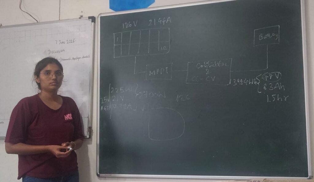
The charging system is designed for a 48 V, 83.2 Ah battery using 12 solar panels, each rated at 225 W, 21 V, and 10.72 A. Under rated operating conditions, the complete PV array can theoretically charge the battery in approximately 1.5 hours.
For 12 solar panels, there are 6 configurations possible
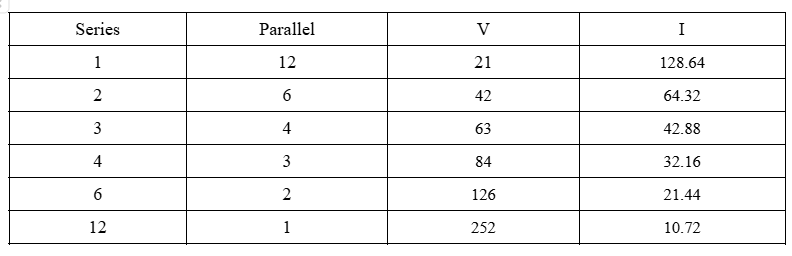
Converter design calculations were performed for each configuration. The first two configurations require only voltage boosting, but the high current values result in significant I²R (conduction) losses, making them less suitable. Therefore, the remaining four configurations were selected for further analysis. These configurations require both step-up and step-down voltage capability depending on the operating conditions.
7 June
To achieve this buck-boost operation, a Ćuk converter was selected. Compared with the conventional buck-boost converter, the Ćuk converter provides a continuous output current, resulting in lower current ripple and making it more suitable for battery charging applications.
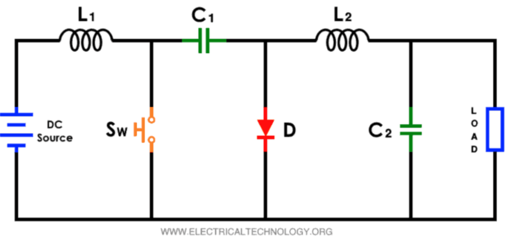
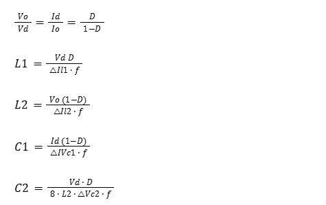
The following are the equations for calculating the values of the components of the converter
8 June
Discussion regarding the converter design
10 June
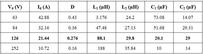
Converter parameter calculations for various values of input voltage and current.
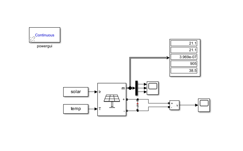
The built-in MATLAB/Simulink solar PV array block was configured with the required series and parallel arrangement of the solar panels and their rated electrical parameters. The model was then supplied with 24-hour irradiance and temperature data from the weather station at Vigyan Ashram to simulate real operating conditions.
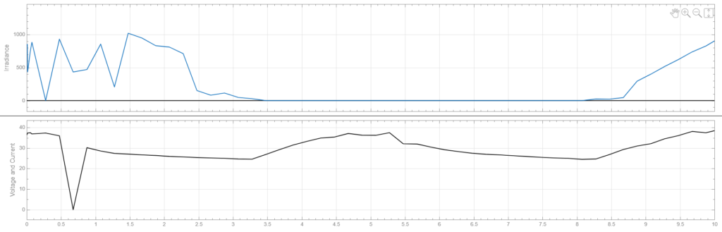
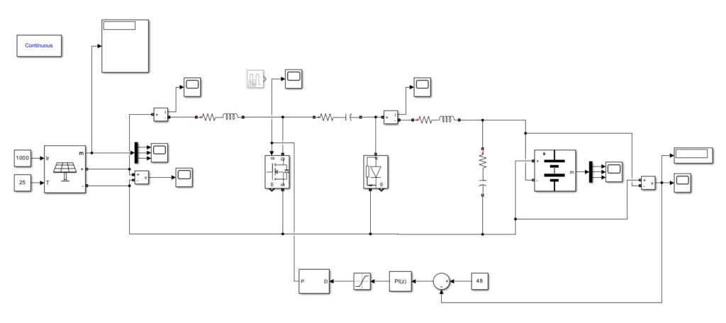
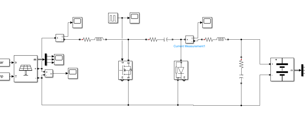
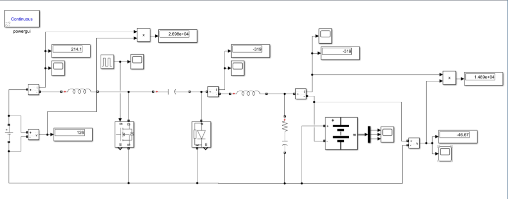
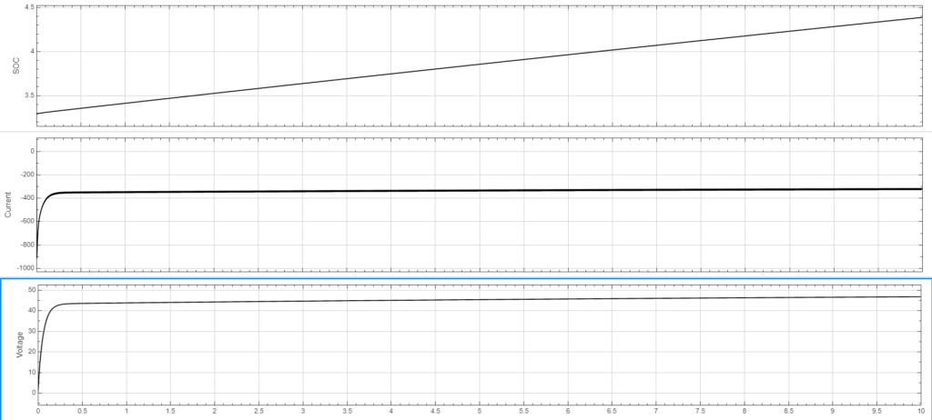
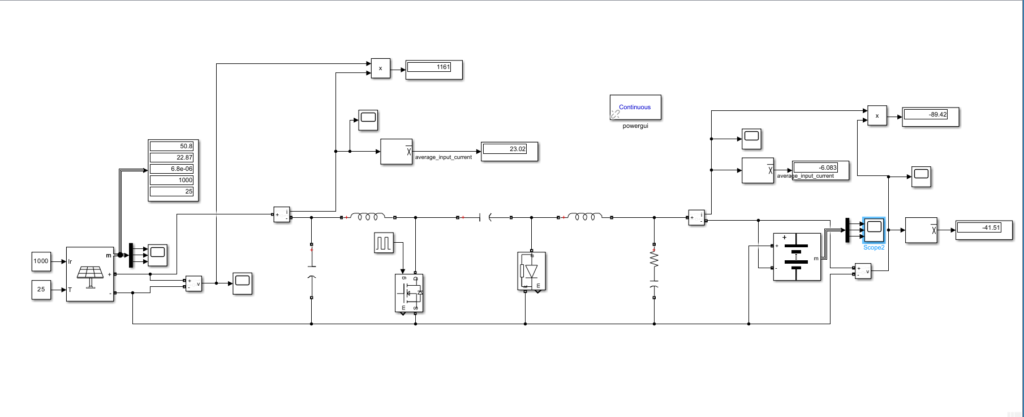
The Ćuk converter circuit was then simulated in MATLAB/Simulink. Initially, the circuit was tested using a constant DC voltage source and a resistive load to verify its operation. Once the converter performed as expected, the DC source was replaced with the solar PV array model, and the resistive load was replaced with the battery model. At each stage of testing, the values of the converter components (inductors and capacitors) were adjusted to achieve the required battery charging performance.
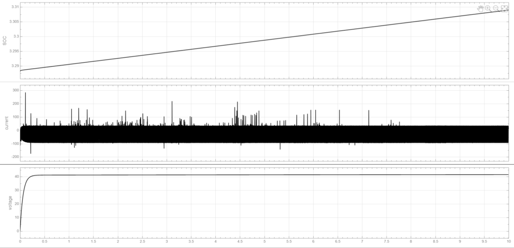
Ongoing control circuit design and further introduction of CC-CV charging