Introduction
Prasad Sir gave to us first assignment. This assignment based on the solidwork which software that learnt the one month training IGTR. This is our first Assignment in Vigyan Ashram just to get use to the process of designing.
week 1
so we got an assignment the design of plate stand. As we were group of four.Sir asked to make four different designs and one of the four design will be selected
16/08/24
Firstly, we went to the mess to take dimension of the vessels for which we wanted to design the stand.The measurement we took we’re as follows:
Plate-Dia=33cm, Ht=2cm
Bowl-Dia=7.7cm, Ht=3.8cm
Spoon -length=15.5cm, Width= 3.8cm
17/08/24
After taking measurement and dimensions of the vessels Prasad sir told us to make a rough design in the our notebook of our own and all design should be different from one another.so we started making our design. While draw the rough sketch, we drew the reference to the dimensions of the previous stand.
Rough Sketch Dimensions:
The dia of the plate that I measured was 33cm so I kept the length of the slot 23cm so as keep the plate partially penetrated to the slot and as thickness if the was 2cm I kept the thickness of the slot as 2.3cm to allow the plate to freely pass through it. Similarly by taking same point in mind I created slot of spoon as well. In this way finished my rough drawing.
18/08/24
After the rough sketch was completed we showed to Prasad sir. Then he told us to make calculation on how much will be the pressure of all the vessels and what is the bearing capacity of our respective structure so we made the calculation as per shown below:
CALCULATIONS: Force = Mass × Acceleration
= 0.6 × 9.8 =5.88 kg m/s = 5.88N
Area = length × Width
=0.245m × 0.13 m= 0.031m2
Now, Pressure = Force/Area =5.88/0.031=189.67 N/m2
By taking some pressure of water assume approximately Pressure =200N/mm2
This is the pressure that will act on the stand
Now let us calculate ultimate stress, by assuming factor of safety as 2
As we know ultimate stress = Allowable stress × factor of safety
200 × 2 =400 N/ m2
20/08/24
Till now we had find out the dimensions of the design, ultimate stress and also figured out the material of the design which is MS sheet but there was one thing missing which was important to create a model in solidwork which we had not found till now was the thickness of the sheet .
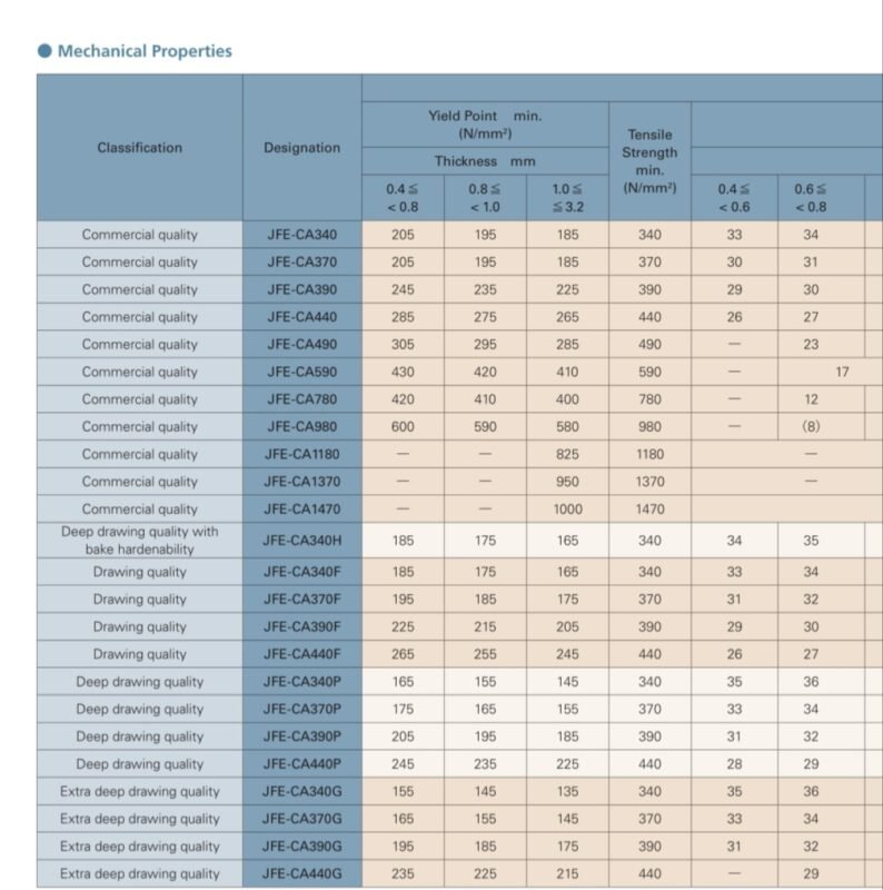
So for finding that we used the ISO sheet for MS sheet. As ultimate stress for our design was 400 N/m2 which we converted to N/mm2 which is 0.004 N/mm2. This value much smaller than the that lowest value of ISO sheet for MS sheet so we took the smaller range of thickness of the sheet which was 0.4mm <0.8mm. At that time in the market 0.8 mm sheet was available so we purchased the 0.8mm sheet for the design.
We found the thickness of sheet metal by refering this chart :
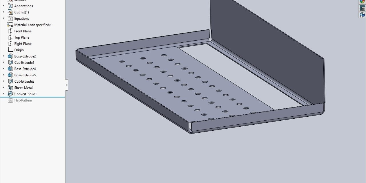
After finding the thickness of metal sheet , then started to create the model on the solidwork software. Following is the model that I created :
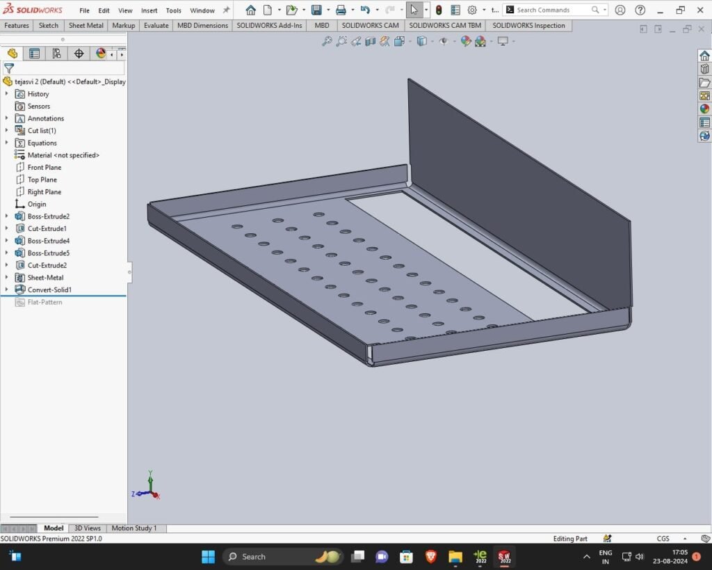
After creation this model we converted into sheet metal because we were going to use plasma cutter use to cut to sheet in desired shape
Given below is the flattened form of the model :
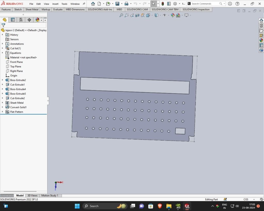
21/08/24
After creation of model I show it to prasad sir. Then he told us to estimate the cost that will be required for making the model.
The calculations of cost is as follows:
Firstly found out the area of the flat form of model
Area = length × Breadth = 40975
Volume = Area × thickness
= 40975 ×0.8 = 32780 m3
Then find Cost of material =volume × Density = 3.2780× 7.96×10^-6×10^4
=26.09×10^-2 = 0.26kg
After finding the cost of material , we asked how much is the price of 1 kg sheet metal in the market. Then the price of sheet metal in the market is 65 RS
23/08/24
After finding the cost of material, Prasad sir told to us cut the flat design of the stand on a cardboard by using laser cutter. After that save the model in DXF file and then take the file in pendrive. Then before cutting the laser cutter, import DXF file and then set it’s speed and power in rdworks software . Power given was 90% and speed was 30mm/s.Then put the cardboard in laser cutter and then started the machine . For the cutting process we connected the pen drive to the laser cutter and copied the RD fine in the laser cutter for doing that we clicked on file button provided on Laser cutter machine the selected option U Disc > Read U disk > Copy to memory > Enter. After that we framed the Laser cutter just to get an idea whether the Laser goes out of the trajectory of our design by clicking frame button. Then we switched on the laser and started cutting. In this way we obtained the rough model of the stand.
This is my final model :
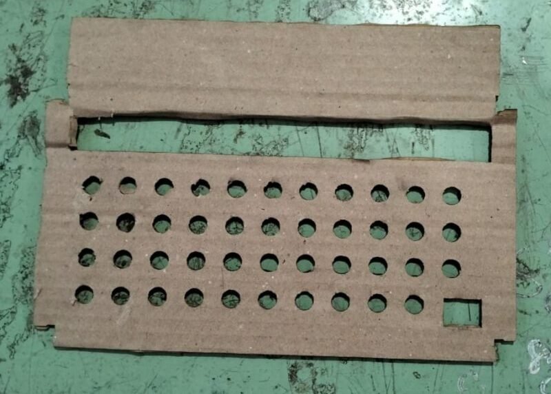
24 /08/24
As we were four working together so each of us made 4 different model in solidworks software and 4 different cardboard models of them which are given below
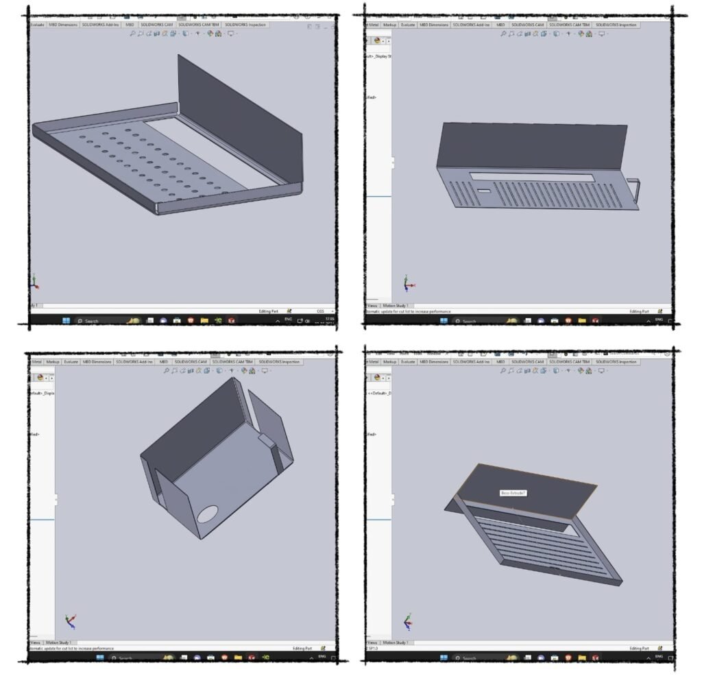
After we cut the cardboard model on laser cutter we showed it to prasad sir. Then Prasad sir told us that there are some mistakes in everyone design. Then he asked to make a new design in the group. After that we discussed and make a design in the book.Then we took the dimensions of the vessels and gave them them a rough design. After giving the dimension we drew the model in solidwork software.
25/08/2024
On this day , we will discuss the type of stress applied on the stand being made. Then Prasad sir and Dixit sir explained the stresses to us.
1.Tensile stress: The ratio of increase in length to original length of the body when it is subjected to pull force.
2.compressive stress : Ratio of decrease in length to original length of the body when it is subjected to a pull force.
After that we learned about types of welding in workshop.
Types of welding in workshop :
Co2 gas welding
Arc welding
After that we again went to DIC lab and converted the model of vessel stand to dxf file and copied it into pendrive. Then we again laser cut the model in FAB Lab by repeating same previous process of laser cutting. Following is the result we got :
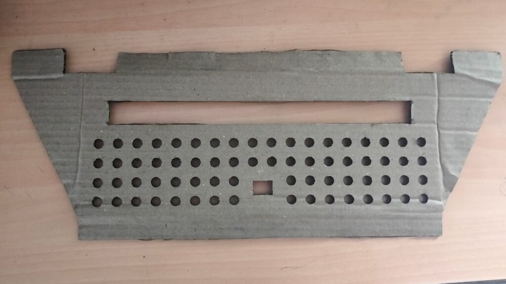
26/08/24
On this day we had discussion about the model that we cut on the laser cutter and Mahesh sir told us to make the slots for the screw. Then we went to kitchen to get and idea from the previous design at that positions we have to create slots for the screws. Then we edited the design again in solidworks and added the slots for the screws. In this design we arranged the vessels and also came to know that the length of the slot for the plate is large that the plate was slipping through the . So we decreased the length of the slot as well. Earlier it was 32 cm and we edited it to 30 cm.Then we again Laser cut on the cardboard using Laser Cutter by repeating same previous process. Following is the model that was created :
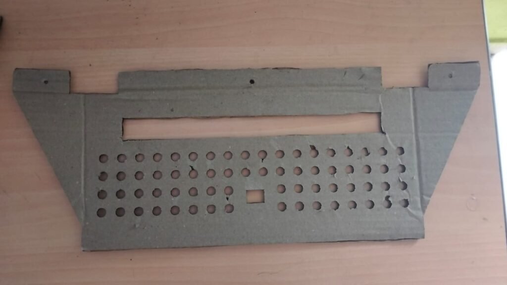
After creation of model we were told to estimate the cost of the material required so we estimated the cost.
CALCULATION :
After creation of model we were told to estimate the cost of the material required so we estimated the cost.
27/08/24 to 1/08/2024
On these date we attend designing thinking training of MSFDA in vigyan ashram
2/09/2024
After creation of model we were told to estimate the cost of the material required so we estimated the cost.
CALCULATION :
Net Weight = Total Volume * Density of MS Total Volume: Area * Thickness = 111276.93 mm2 * 0.8 mm = 89021.544 mm3
Net Weight = 89021.544mm3* (7.8 * 10- 6 Kg/mm3)
Net Weight = 0.708kg Now, Cost of MS steel per kg = Rs 65
Cost for 0.34 kg Mild Steel = 65 * 0.708 = Rs 46.02
Net Weight = Total Volume * Density of
3/09/2024
Again we showed the new model created to the Prasad sir and then he told us to bring some more modifications in the new design and also focus on some cost cutting. So we again edited this new design and we came to know that the part that we created to hold the plate and avoid it from touching the wall contains a lot of unnecessary material which results in increase in the cost. So we decided to remove the unnecessary material from that part.
24/09/24
We went to the workshop for plasma cutting to cut the design of the vessel stand, but because we used the machine after a long time, there was a problem in starting the machine.so plasma cutting was not completed.
25/09/24
As the plasma cutting machine was repaired we went to workshop again to cut out design. Before cutting the design first Mahesh sir explained us how to operate the plasma cutting machine and after that for practice he gave us small parts to cut by ourselves as a assignment then all three of us did that.
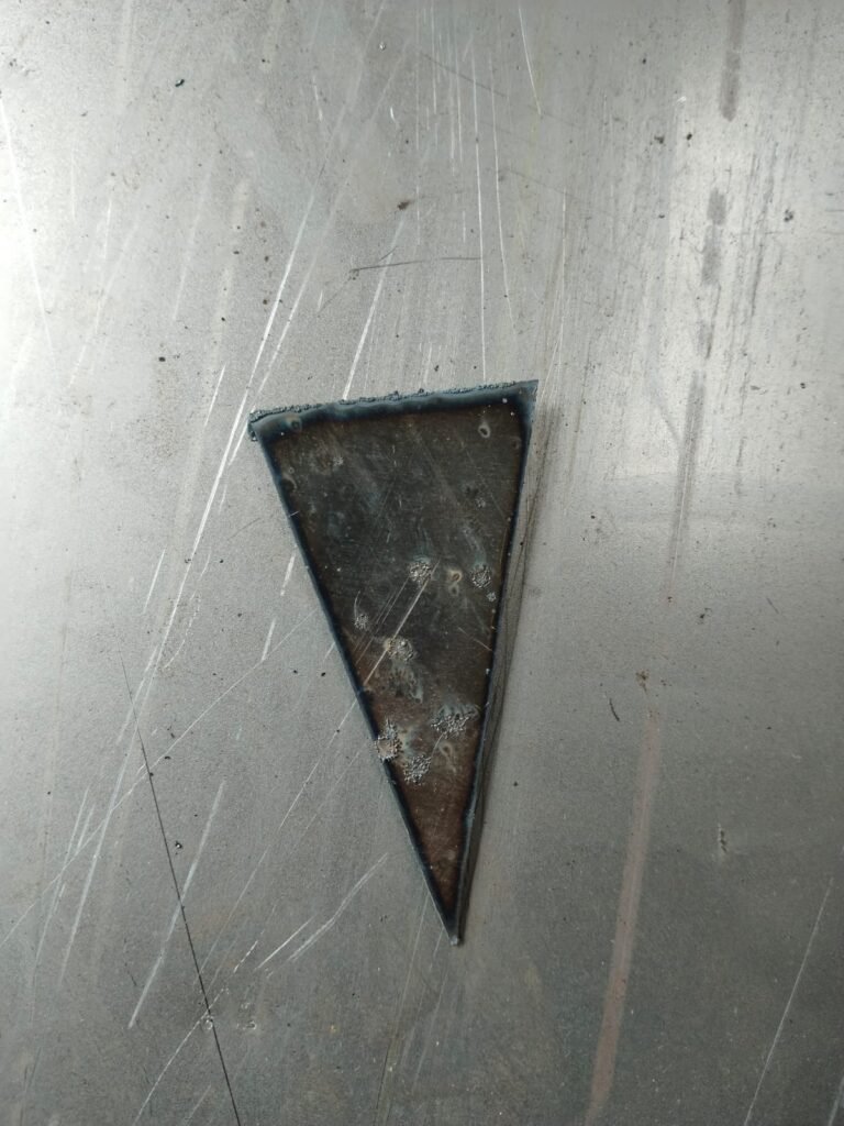
After that we again used old sheet for trail then the problem occured was that the machine was unable to cut the holes of our required dimensions properly. We made some attempts but it was causing same problem so Mahesh Sir told us to change the design and increase the size of holes and reduce the number of holes.
27/09/24
According to the limitations of plasma cutting, we designed it in solidwork.
After creation of model we were told to estimate the cost of the material required so we estimated the cost.
CALCULATION:
Net Weight = Total Volume * Density of MS
Total Volume: Area * Thickness = 76146.33mm2 * 0.8 mm = 60917.064 mm3
Net Weight = 60914.064 mm3* (7.8 * 10-6 Kg/mm3)
Net Weight = 0.48kg
Now, Cost of MS steel per kg = Rs 65
Cost for 0.34 kg Mild Steel = 65 * 0.47 = Rs 31.2
Then we cut it on the plasma cutter, it was not designed accurately, because it was not a sheet plane, so the cut did not fit on it. Then we took a new plane sheet from the workshop and then cut 7 designs on it.
28/09/24
After plasma cutting, grind the edges of the cut job because it should not hurt anyone while using it.
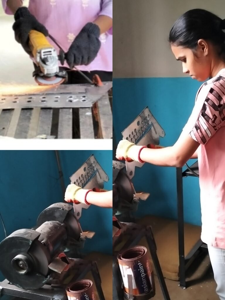
29/09/24
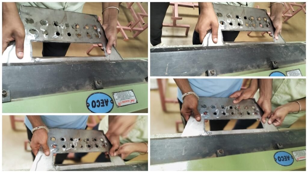
After grinding operation We did the bending of the job. We used the bending machine in the workshop to do the bending operation.
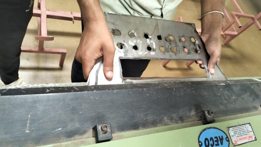
30/09/24
Some stands were remained for bending so we started doing it. All the stands were properly bent today.
1/10/24
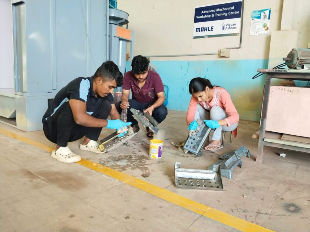
After grinding, we did powder coating. Before powder coating, we cleaned the stands with acid to remove and clean rust particle on that stand. After applying acid, wash it with clean water and keep it to dry for some time.
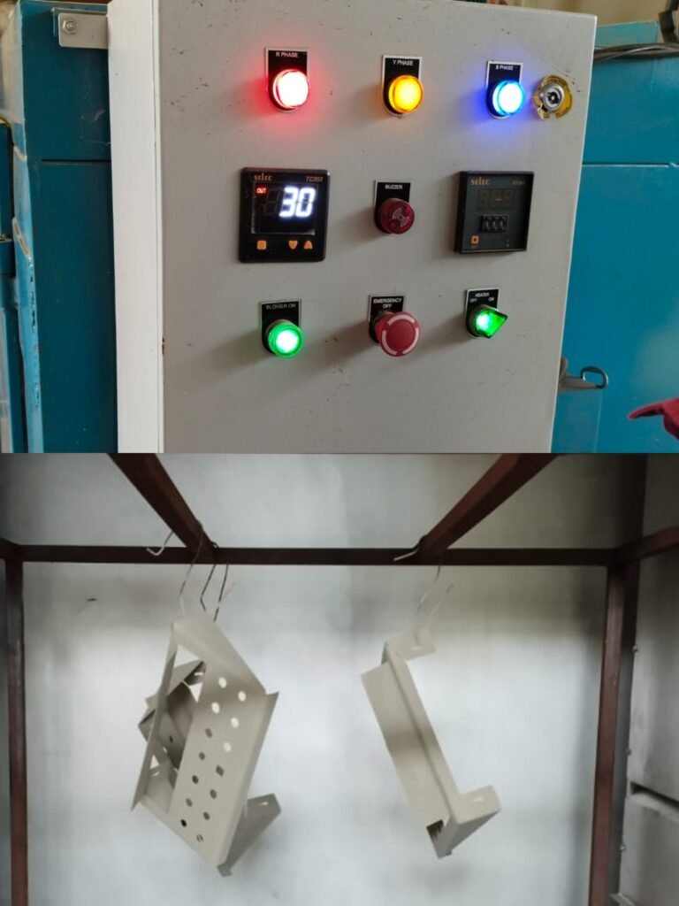
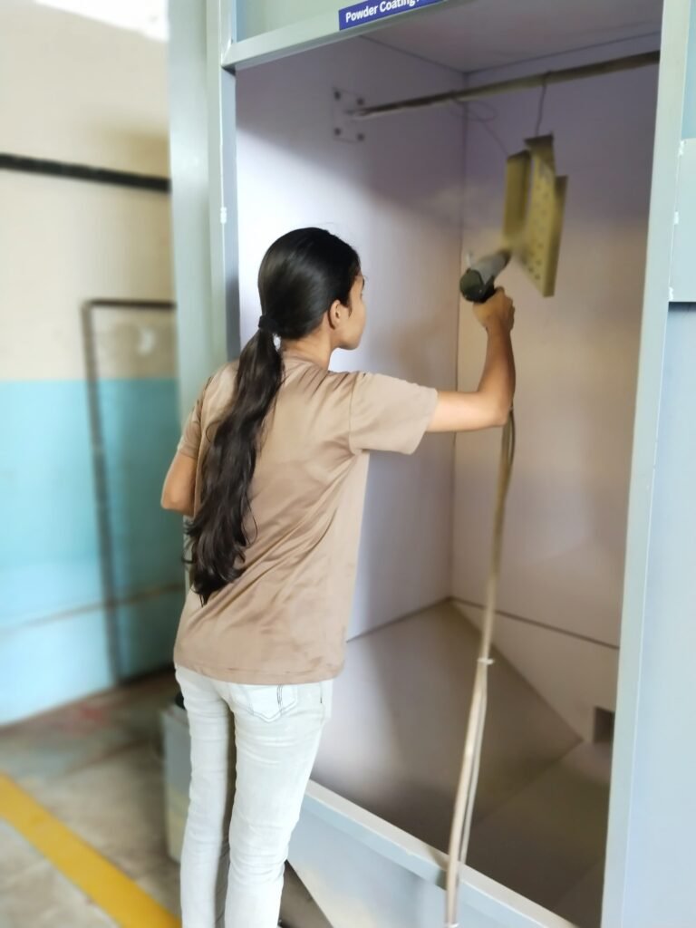
After hanging the stands in the machine of powder coating, powder coating was done on that stand with one special gun to spray powder. After that the stands were removed out of the machine and then they were placed in the container for heating upto the temp of 150 degrees. It took about 2 hours to complete.
2/09/24
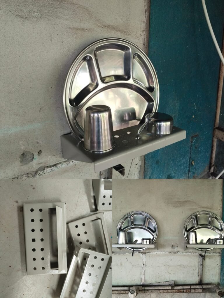
Today we installed the stands in the kitchen. We first bought screws of 4 mm from the market. Then we fitted all the stands on the wall before that we first removed the previous stands. The last three stands were fitted using the tar because screws were not possible there due to windows grill. And our first assignment was completed.
