The Challenge Begins – Jun 21
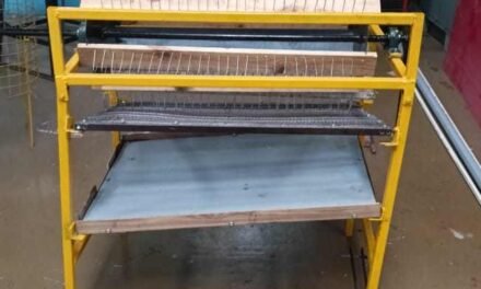
Hello everyone! I’ve been assigned an exciting new project as an intern: restoring a convection air dryer. Let me walk you through how it works.


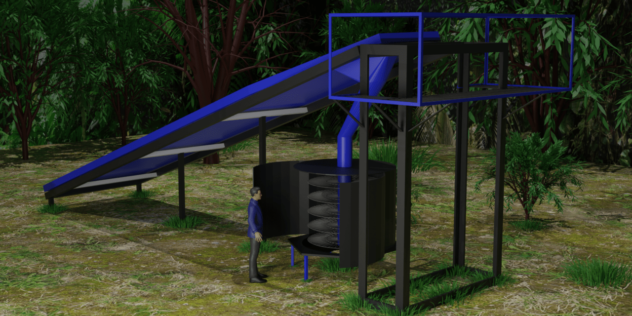
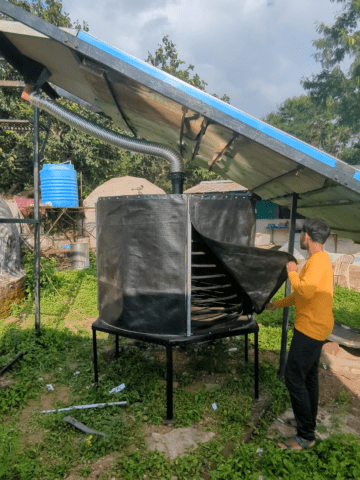
The air dryer operates on the principle of convection. When sunlight strikes the glass surface, it heats up. This heated air is then drawn in through the vents at the bottom end and begins to rise inside the sloped structure. Insulation foam is used on the bottom side of the slope to prevent heat loss. The hot air is subsequently directed to a chamber through a pipe using an AC fan. Unfortunately, the current setup is incomplete and non-functional. Parts are missing, and rain has caused rust on the bars of the chamber. My task is to get this air dryer up and running again.
Repainting and Sealing a panel – Jun 21


During my inspection, I noticed one of the top panels was missing. Upon locating it, I found it in poor condition and decided to repaint it. I retrieved some black paint from the workshop and recolored the panel. Painting it black, instead of its original white, ensures it absorbs more light and heats up more efficiently.


Additionally, I realized that air might leak through the gaps, so I sourced a rubber tube to seal these gaps and make the structure airtight.
Securing the Panel – Jun 22


For securing the newly painted panel, I used self-drilling screws, which are designed to create their own holes in metal or wood. This simplifies the construction process by eliminating the need for pre-drilling. I tied a metal wire to the colored sheet and prepared to pull it up 12 feet to secure it in place.


With no one around to assist, I had to improvise and tackle the task solo. This was quite risky as strong winds were blowing, and the sheet seemed like it wanted to take flight. The sharp edges posed a real hazard, and I had to bend at awkward angles to reach the securing point, constantly aware of the risk of falling from the platform. Despite these challenges, I managed to creatively secure the sheet in place.
Fixing the broken Door – Jun 24


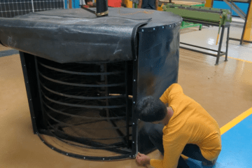
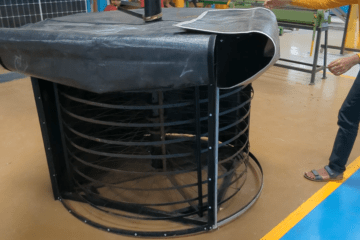
Next on the list was the broken door, which was in terrible condition. The joints needed welding first, and I’d like to give a shoutout to the welder who helped with this task with those tools!


After the welding was completed, I removed the old, deteriorating sheet and cut a new one. I had never done any sort of stitching before, and my first attempt involved using an 8-inch needle and thick plastic thread. The PVC sheet proved to be extremely tough to stitch. To make the task a bit easier, I used clamps to hold everything in place. Even with the clamps, it took me 2 hours to stitch it all together! After fixing the hinges, the door looked brand new. Now, I just have to repeat this process for all the other sheets of the chamber.
CAD Model for Laser Cutting – Jul 20


Creating a durable and efficient base for a dryer involves choosing the right materials and using precise techniques. I designed a hexagonal dryer base in SolidWorks and decided to use stainless steel instead of plastic sheets. Stitching plastic into this shape is difficult, and it tends to wear out over time, so stainless steel is a better choice. To make the base, I will cut triangular pieces from a 0.6 mm stainless steel sheet using DXF format files for accuracy. These pieces will be carefully welded together to form a conical shape at the bottom. This method not only makes the dryer base stronger but also showcases careful craftsmanship and innovative design.
3D Model for representation – Jul 20


Creating a 3D model of the dryer structure makes it much easier to show and explain the design to people. With a 3D model, we can show the dryer from different angles, so everyone can see how it looks and fits together. This helps people understand the design better. We can also break the model into parts to show how each piece connects and works. This detailed view makes it clearer how the dryer is built. Even though the 3D modeling is still in the early stages, it makes the presentation more interesting and helps show the careful planning and innovative ideas behind the project.
Material and colour – Jul 22


Showing isometric views of the dryer structure and coloring it according to the original design helps make the presentation clearer and more realistic. Isometric views allow people to see the design from a 3D perspective, making it easier to understand the shape and layout. Adding the original colors helps people visualize how the final product will look, making the design more relatable and engaging. This approach makes the presentation more effective and helps communicate the design ideas better.
Rendering, Lighting and other elements – Jul 22


The clear difference lighting and background elements can make. The first image has no lighting or background elements like trees and grass, while the second image includes them. The second image looks more realistic and appealing, showing how lighting and background details can enhance the presentation and give a better sense of how the design will look in a real environment. This comparison helps highlight the importance of these elements in making the design more engaging and easier to visualize.
Comparing the render to the original – Jul 22


I created beautiful renders of the dryer structure and compared them to the actual structure from the same angles. This comparison helps highlight the accuracy and detail of the renders, showing how closely they match the real thing. By presenting both the renders and the actual structure side by side, it becomes easier for viewers to appreciate the design and understand how it translates from a digital model to a physical object. This approach enhances the presentation, making it more engaging and informative.
Plasma cut out hexagon – Aug 7th


I needed to cover the base of a frame, so I started by designing a CAD file that matched the exact shape and size I needed. I went with a hexagonal design, made up of six petals. Using a plasma cutter, I precisely cut out the shape from the material. Afterward, I bent the edges of each petal, which made it easier to join them together and form a solid, sturdy base.
The reason I chose this design was to ensure a strong structure that also looked clean and symmetrical. The bending of the petals allowed for better alignment and strength when the pieces were joined.
Creating the Base for a Frame – Aug 7th
For this project, I needed to cover the base of a frame, and accuracy was key. I began by designing a CAD file to get the exact measurements and layout. The design I chose was a hexagonal shape made up of six individual petals. This design wasn’t just for aesthetics—it also allowed for better structural integrity when all the pieces would come together.
Once the design was ready, I used a plasma cutter to cut out the shape from the material. Plasma cutting was the ideal choice here because it provides precision and clean edges, which is important for a piece like this where all the parts need to fit together smoothly.
After cutting, I bent the edges of all six petals. This was necessary because bending allowed me to create a snug fit when assembling the pieces, ensuring that the final structure would be strong and stable. The bending also helped with alignment, making sure everything fit perfectly once joined.
This process helped me achieve a sturdy base that not only serves its functional purpose but also looks symmetrical.


Metal base ready – Aug 8th
Next, I flipped the hexagonal structure over so it had a smooth surface on one side, and all the joints were neatly hidden on the other. This step is similar to how you’d fold paper to make a cube, where all the joins are inside. The smooth side of the hexagon would be the visible part of the base, giving it a clean, polished look.
Finally, I secured the hexagon to the frame using self-fastening screws. These screws were perfect for the job because they don’t require pre-drilling, and they provided a strong, secure hold to make sure the base stayed firmly attached to the frame.


Colouring the base – Aug 10th
Once the base was securely attached to the frame, the next step was making sure the entire structure was airtight. To do this, I filled any cavities or gaps with silicone. This helped seal everything up tightly and ensured that no moisture or air could get inside, which is important for long-term durability.
With the structure now airtight, I moved on to painting. First, I applied a layer of red oxide spray paint. This type of paint is great for preventing rust, especially since metal structures can be prone to corrosion over time. The red oxide serves as a protective layer, keeping the frame in good condition for years to come.
After the rust-proofing layer dried, I finished it off with a coat of black Japan paint. This paint has a matte finish this gives the frame a durable and scratch-resistant surface.


Designing and Cutting the Top Cover – Aug 23rd
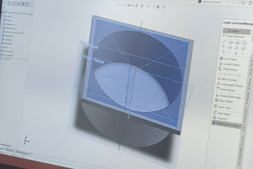
After completing the base, I had to make a cover for the top of the frame. Using the same approach, I designed a file in SolidWorks to match the exact measurements needed for the top. This time, instead of a hexagon, I had to create a large circle. Since the circle was too big to cut in one go, I split the design into two hemispheres.
To bring this design to life, I used a 0.6 mm steel sheet. The thinner steel made it easier to work with, especially for creating a smooth, round shape. I cut out the two hemispheres, which would eventually be joined together to form the full circular top cover.


Fitting the Top Cover – Aug 25th
With the two hemispheres cut out, the next step was to prepare them for installation. I had to cut small grooves around the edge of the circle. These grooves made it easier to bend the steel into the desired shape. I used a hammer to gently shape the edges, which helped the cover fit snugly against the frame.
Once the cover was shaped, I secured it to the frame using self-fastening screws. These screws made the installation process straightforward and efficient, as they didn’t require pre-drilling.
I was thrilled with how the top cover turned out. The finish was even better than I had, adding a professional look to the entire structure.


Preparing and Painting the Frame – Aug 27th
Once the top cover was completed and the cover was removed, I turned my attention back to the cylindrical frame. The first step was to sand the frame thoroughly. This step was crucial to remove any imperfections and to create a smooth surface that would ensure the paint adhered properly.
After sanding, I repeated the painting process used for the base. I applied a coat of red oxide spray paint to protect the frame from rust. This layer helps safeguard the metal against corrosion, which is important for durability. Once the red oxide paint dried, I followed up with a coat of black Japan paint. The black Japan paint not only provided a sleek, matte finish but also added an extra layer of protection against scratches and wear.
This process ensured that the entire structure had a consistent look and was well-protected, making it both functional and aesthetically pleasing.


Installing the Doors with Velcro – Aug 31st
For the doors of the structure, I decided to use a thick plastic sheet. To make them easy to attach and remove, I chose Velcro as the fastening mechanism.
I began by securing one side of the Velcro strips to the frame. I screwed these strips into place to ensure a strong and reliable hold. Next, I attached the corresponding Velcro strips to the plastic sheet. This setup will allow the doors to be easily attached to and removed from the frame, providing both convenience and flexibility.


Securing the Plastic Door – Sep 2nd
To complete the door for the structure, I used a thick 500 gsm plastic sheet that extends down from all four sides of the frame. To ensure it stays in place and maintains an airtight seal, I attached Velcro strips to three sides of the plastic sheet: the right, left, and bottom edges. These strips are designed to adhere securely to the frame and allow for easy attachment and removal.
The installation process involves positioning the plastic sheet so that it is sandwiched between the frame and the top cover of the structure. Once the Velcro strips on the plastic sheet are aligned with their counterparts on the frame, the sheet will be folded over itself at the edges. This folding action creates a snug fit and an airtight seal around the door area, preventing any air or moisture from escaping.
By using this method, I ensure that the door is not only secure and stable but also provides an effective barrier against the elements, enhancing the overall functionality of the structure.

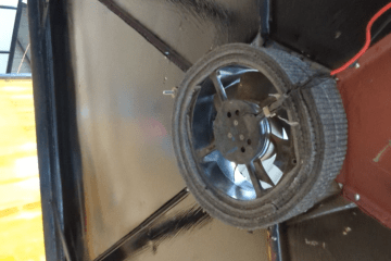
Installing the Exhaust Fan – Sep 3rd
To complete the setup, I needed to install an exhaust fan in the base of the structure. First, I sealed the opening where the fan would be mounted using insulation. This helped create a tight fit and improved the overall efficiency of the fan.
After installing the insulation, I covered any remaining small gaps around the opening with silicone. This ensured that the fan was securely fixed and that no air or moisture could escape.
Additionally, I noticed a few gaps in the base that I hadn’t caught earlier. To address these, I reapplied silicone to ensure that the base was fully sealed and airtight. This extra step was crucial for maintaining the structure’s integrity and performance.


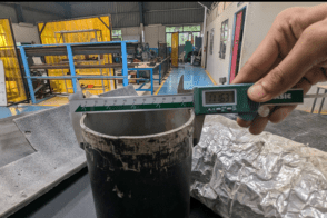
Creating and Installing the Intake Fan Adapter – Sept 7th
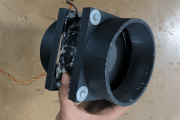
An intake fan was required for the project, and it needed to be attached to a pipe. To ensure a perfect fit, I started by measuring the pipe and then designing a 3D model of the adapter. After creating the model, I 3D printed it to the exact specifications needed.
Once the print was complete, I sanded the adapter to smooth out any rough edges and then heated it to make sure it conformed perfectly to the pipe. After achieving the right shape and fit, I painted the adapter to match the overall design of the structure.
Finally, I attached the adapter to the fan. With this setup, the fan now fits onto the pipe seamlessly, ensuring efficient airflow and a neat finish.


Final Assembly and Functionality- Sep 8th
With all the individual components ready, I finally assembled the structure. Every part I had meticulously designed, cut, painted, and prepared came together smoothly. The structure is now fully functional, and I’m really pleased with the outcome.
One major upgrade was moving from a plastic sheet-covered frame to one with a solid metal base and top. This material change has not only made the structure more durable but also given it a much sleeker and stronger finish. Additionally, the biggest issue I faced initially—making the structure airtight—has been completely solved. Thanks to the silicone seals, the careful fitting of each part, and the airtight door mechanism, the structure now holds air perfectly.


Upgrading the Air Duct – Sep 9th
One of the critical components of the structure is the pipe that carries hot air from the solar slope to the drying chamber. This pipe plays a vital role in the system, as it channels the heated air necessary for the drying process. However, the original pipe was in poor condition and wasn’t performing.
To improve the system’s efficiency and prevent heat loss, I replaced the old pipe with an aluminum duct. Aluminum is a much better material for this purpose because it not only resists wear and tear but also helps retain heat more effectively. This upgrade ensures that the hot air reaches the drying chamber without significant temperature loss, making the drying process more efficient and consistent.


Restoration Project: Before and After – Sept 10th
This project involved restoring an old food dryer and improving both its functionality and durability. Initially, the structure was covered mostly in plastic sheets and lacked an airtight seal, which caused inefficiencies. The original 5-inch pipe, responsible for carrying hot air, was also in poor condition, leading to heat loss.
Through a series of upgrades and careful craftsmanship, I completely transformed the structure. Here’s a quick look at the changes made:
Before:
- Mostly covered in plastic sheets
- Old rusty pipe causing heat loss
- Structure wasn’t airtight
- Inconsistent airflow and insulation issues
After:
- Replaced plastic with metal for the base and top
- Installed an aluminum duct to replace the old pipe, preventing heat loss
- Sealed all gaps with silicone, ensuring an airtight structure
- Designed and installed a functional plastic door with a Velcro mechanism
- Added intake and exhaust fans for improved ventilation and airflow
The final result is a fully functional, airtight, and efficient structure that not only looks better but also performs much more effectively.


Note- If the dryer isn’t functioning properly, it could be due to the intake or exhaust fans running for too long. Make sure to monitor the duration they’re on, as this can affect airflow and temperature regulation. Another possible issue could be the alignment of the pipe hole adjusting them might help optimize airflow and improve the dryer’s performance.
