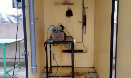
This project is built upon the work done by Carbon Robotics (video). The objective of this project is to explore the feasibility of implementing their technology for an application at Vigyan Ashram.
Initial Thoughts: Since this project is relatively new to Vigyan Ashram, the first step involved contemplating the potential stages based on existing scientific literature and Vigyan Ashram’s objectives. After several days of research, four preliminary areas of focus were identified:
- Laser Weeding Analysis (using lasers to eliminate unwanted plants) Progress [70/100]
- Mechanism Structure [20/100]
- Plant Detection Methods: Plant Image Processing [10/100]
- Laser control how to control the laser movement [0/100]
Project Progress:
Stage 1: First Prototype, Initial Testing, Electrical Diagram, Bibliography Review.
Objective: The primary goal of the project is to gain a deeper understanding of laser weeding techniques. While numerous scientific papers have explored this topic in recent years, none have tailored the research to India’s specific conditions. A key objective is to create a test bed to determine the limitations of using lasers in Indian farms. This involves selecting target plants and exploring laser weeding methods: emitting enough power to completely burn the plant or just enough power to disrupt the plant (at the DNA level?). The ultimate aim is a scientific study exploring optimal parameters (laser power, required energy, beam diameter) for the most effective weed elimination (exposure time, percentage of dead plants vs. material killed) for the most common plants found in Indian farms.
Initial Testing: A testing bench, as shown in the above photo, was created to assess our laser’s efficiency. In our case, a 12-watt laser (delivering a maximum of 10W) was used (link). Several tests were conducted to determine if it could swiftly cut plants of various thicknesses. The results were positive, as shown in the figures (plants cut with different durations and power in joules).


Prototype: After conducting these initial tests, it was time to move to real-world testing, targeting upright plants. To enhance precision, a prototype was developed, incorporating a camera equipped with a crosshair to improve targeting accuracy.

Design Evolution: [Computer-Aided Design (CAD) Figures 1/2] [Implementation Figures 1/2]


Technical Considerations (Code/Electrical Diagram/Prototype Schema):
- Prototype Schema

- Camera: Code, Electrical Diagram, Datasheet
The camera module is divided into three parts: the web server for viewing the live image, the crosshair that determines the real position of the laser, and the camera programming section.
Programming: To program the camera, the following schema must be followed, based on the tutorial adapted for our ESP AI camera.
Crosshair: A Python program has been developed to create a crosshair that is added to the web server image, indicating the crosshair’s position. Its location can be adjusted relative to the camera-laser position.
The code can be found on the following Drive
Web Server: One of the challenges of the prototype is to aim the target correctly. For this purpose, a live image is sent to the prototype’s smartphone module. The code for this functionality is extracted from the following tutorial and can be found on Drive


Laser: Code, Electrical Diagram, Datasheet: The laser used is a 12W (10W effective) 435 nm laser. It needs to be powered with 12V, and its power can be adjusted using a TTL logic signal.
Code: The laser management code is based on a TTL power supply that outputs between 0 and 5V depending on the value of a potentiometer.
The code can be found on Drive
Global Circuit:
The overall circuit consists of the laser, its controller, a power switch, a 12V power supply, an Arduino, an ESP32-CAM, and a potentiometer that controls the TTL of the laser. Here is a breakdown of the components and their roles:
- Laser: A 12W (10W effective) 435 nm laser used for the intended purpose.
- Laser Controller: Manages the laser’s power and controls its output. It receives signals from the Arduino to adjust the laser’s intensity.
- Power Switch: Controls the power supply to the entire system. It enables or disables the power flow to the components.
- 12V Power Supply: Provides the necessary power to the laser and other components in the circuit.
- Arduino: Acts as a microcontroller, receiving input from various sensors or interfaces and sending signals to control the laser intensity and other functions in the system.
- ESP32-CAM: An ESP32-based development board with a camera module. It give a real time image of what happening and help with crosshair pointing
- Potentiometer: Adjusts the TTL (Transistor-Transistor Logic) signal sent to the laser controller, allowing the laser’s power output to be controlled based on the potentiometer’s position.


