Introduction
Temperature and humidity are the most commonly measured environmental parameters. A temperature and humidity measurement device was deployed in Vigyan Ashram a few years ago. This display went through a lot of changes and eventually stopped working due to failure in the the 7 segment display. The system was removed and tested and had minor fluctuations in the readings but due to its bulky size and high maintenance, it was decided to make a new display. The new display needed to be cost effective, portable and reliable, therefore a new display was made using AHT25 temperature and humidity sensor and P10 board for display.
Material
- ESP32/ Arduino Uno
- AHT25 temperature and humidity sensor with stainless steel casing
- Single color, P10 Led board with 16 pin flat ribbon cable (FRC)
- 5V, 2A adapter
- Wires for connection
- Laser cut acrylic sheet
- 3D printed cover for the
- Junction box
- Female DC jack
- Cable gland
- Screws
Methodology
Making the circuit
The temperature and humidity display circuit was tried out on both, ESP32 as well as Arduino UNO.
The AHT25 uses I2C communication and therefore is connected to SDA and SCL pins of the micro-controller boards respectively.
| AHT25 | Arduino UNO | ESP32 |
| SDA (Yellow) | A4 | GPIO 21 |
| SCL (White) | A5 | GPIO 22 |
| VCC (Red) | 5V | 3.3V |
| GND (Black) | GND | GND |
The P10 board has 16 pins out of which 7 must be connected to the microcontroller (Enable, A, B, CLK, SCLK,DATA, GND) .

The P10 board is connected to the micro-controller as per the pins defined in the libraries, DMD/DMD32 for Arduino UNO and ESP32 respectively. In case of ESP32 the D22 and D21 pins are already used up for the I2C communication of AHT25 sensor therefore we change the pins in the header file in order to avoid interference. The header file can be found in the program file/Arduino/libraries/DMD32 or in the documents folder. Make the necessary changes to the header files.
| P10 LED board | Arduino UNO | ESP 32 |
| Enable | 9 | D4 (D22) |
| A | 6 | D19 |
| B | 7 | D15 (D21) |
| CLK | 13 | D18 |
| SCLK | 8 | D2 |
| DATA | 11 | D23 |
| GND | GND | GND |

Uploading the code
Install the required libraries, Adafruit_AHTX0, DMD32(for ESP32) and DMD/DMD2 (for Arduino UNO)
//*************************************************ESP32+AHT+P10*****************************************//

#include <Adafruit_AHTX0.h>
Adafruit_AHTX0 aht;

#include <DMD32.h>        //
#include <fonts/SystemFont5x7.h>
#include <fonts/Arial_Black_16.h>
//Fire up the DMD library as dmd
#define DISPLAYS_ACROSS 1
#define DISPLAYS_DOWN 1
DMD dmd(DISPLAYS_ACROSS, DISPLAYS_DOWN);
//Timer setup
//create a hardware timer  of ESP32
hw_timer_t * timer = NULL;

// Variable to hold temperature and humidity readings
float t;
float h;
/*--------------------------------------------------------------------------------------
  Initiating AHT sensor
--------------------------------------------------------------------------------------*/
void initAHT()
{

  if (! aht.begin()) {
    Serial.println("Could not find AHT? Check wiring");
    while (1) delay(10);
  }
  Serial.println("AHT10 or AHT20 found");
}

/*--------------------------------------------------------------------------------------
  Interrupt handler for Timer1 (TimerOne) driven DMD refresh scanning, this gets
  called at the period set in Timer1.initialize();
--------------------------------------------------------------------------------------*/
void IRAM_ATTR triggerScan()
{
  dmd.scanDisplayBySPI();
}


void setup() {
  Serial.begin(115200);  //Initialize serial
  initAHT();

//*****************DMD***********************************//
  // return the clock speed of the CPU
  uint8_t cpuClock = ESP.getCpuFreqMHz();
  // Use 1st timer of 4
  // devide cpu clock speed on its speed value by MHz to get 1us for each signal  of the timer
  timer = timerBegin(0, cpuClock, true);
  // Attach triggerScan function to our timer
  timerAttachInterrupt(timer, &triggerScan, true);
  // Set alarm to call triggerScan function
  // Repeat the alarm (third parameter)
  timerAlarmWrite(timer, 300, true);

  // Start an alarm
  timerAlarmEnable(timer);

  //clear/init the DMD pixels held in RAM
  dmd.clearScreen( true );   //true is normal (all pixels off), false is negative (all pixels on)

}

void loop()
{

  // Get a new temperature reading
  sensors_event_t humidity, temp;
  aht.getEvent(&humidity, &temp);// populate temp and humidity objects with fresh data
  t = temp.temperature;
  Serial.print("Temperatqure (ºC): "); Serial.println(t);
  h = humidity.relative_humidity;
  Serial.print("Humidity (%): ");Serial.println(h);
  delay(1000);

  /*------------DMD display-----------------------------------------------*/
  byte b;

   // 10 x 14 font clock, including demo of OR and NOR modes for pixels so that the flashing colon can be overlayed
   dmd.clearScreen(true);
   dmd.selectFont(Arial_Black_16);

   dmd.drawMarquee("WELCOME TO VIGYAN ASHRAM",24,(32*DISPLAYS_ACROSS)-1,0);
   long start=millis();
   long timer=start;
   boolean ret=false;
   while(!ret){
     if ((timer+50) < millis()) {
       ret=dmd.stepMarquee(-1,0);
       timer=millis();
     }
   }

  char st [3];
  String str2;
  str2=String(t);
  str2.toCharArray(st,3);
  char sh [3];
  String str3;
  str3=String(h);
  str3.toCharArray(sh,3);

     dmd.clearScreen( true );
     dmd.selectFont(System5x7);
     for (byte x=0;x<DISPLAYS_ACROSS;x++) {
     for (byte y=0;y<DISPLAYS_DOWN;y++)   {
     dmd.drawString(  2+(32*x),  1+(16*y), "T:", 2, GRAPHICS_NORMAL );
     dmd.drawString(  2+(32*x),  9+(16*y), "H:", 2, GRAPHICS_NORMAL );
     }
     }

     dmd.selectFont(System5x7);
     for (byte x=0;x<DISPLAYS_ACROSS;x++) {
     for (byte y=0;y<DISPLAYS_DOWN;y++)   {
     dmd.drawString(  11+(32*x),  0+(16*y), st, 3, GRAPHICS_NORMAL );
     dmd.drawString(  11+(32*x),  9+(16*y), sh, 3, GRAPHICS_NORMAL );
     }
     }

     dmd.drawCircle( 24,  1,  1, GRAPHICS_NORMAL );

     dmd.selectFont(System5x7);
     for (byte x=0;x<DISPLAYS_ACROSS;x++) {
     for (byte y=0;y<DISPLAYS_DOWN;y++)   {
     dmd.drawString(  27+(32*x),  0+(16*y), "C", 2, GRAPHICS_NORMAL );
     dmd.drawString(  27+(32*x),  9+(16*y), "%", 2, GRAPHICS_NORMAL );
     }
     }
  delay(11000);

}
//**********************************ArduinoUNO+AHT+P10**********************************//

#include <Adafruit_AHTX0.h>
Adafruit_AHTX0 aht;
#include <SPI.h>        //SPI.h must be included as DMD is written by SPI (the IDE complains otherwise)
#include <DMD.h>        //
#include <TimerOne.h>   //
#include "SystemFont5x7.h"
#include "Arial_black_16.h"

//Fire up the DMD library as dmd
#define DISPLAYS_ACROSS 1
#define DISPLAYS_DOWN 1
DMD dmd(DISPLAYS_ACROSS, DISPLAYS_DOWN);

// Variable to hold temperature and humidity readings
float t;
float h;
/*--------------------------------------------------------------------------------------
  Initiating AHT sensor
--------------------------------------------------------------------------------------*/
void initAHT()
{

  if (! aht.begin()) {
    Serial.println("Could not find AHT? Check wiring");
    while (1) delay(10);
  }
  Serial.println("AHT10 or AHT20 found");
}

/*--------------------------------------------------------------------------------------
  Interrupt handler for Timer1 (TimerOne) driven DMD refresh scanning, this gets
  called at the period set in Timer1.initialize();
--------------------------------------------------------------------------------------*/
void ScanDMD()
{
  dmd.scanDisplayBySPI();
}

void setup(void)
{
  Serial.begin(115200);  //Initialize serial
  initAHT();
  Timer1.initialize( 5000 );           //period in microseconds to call ScanDMD. Anything longer than 5000 (5ms) and you can see flicker.
  Timer1.attachInterrupt( ScanDMD );   //attach the Timer1 interrupt to ScanDMD which goes to dmd.scanDisplayBySPI()

  //clear/init the DMD pixels held in RAM
  dmd.clearScreen( true );   //true is normal (all pixels off), false is negative (all pixels on)

}

void loop()
{

  // Get a new temperature reading
  sensors_event_t humidity, temp;
  aht.getEvent(&humidity, &temp);// populate temp and humidity objects with fresh data
  t = temp.temperature;
  Serial.print("Temperatqure (ºC): "); Serial.println(t);
  h = humidity.relative_humidity;
  Serial.print("Humidity (%): ");Serial.println(h);
  delay(1000);

  /*------------DMD display-----------------------------------------------*/
  byte b;

   // 10 x 14 font clock, including demo of OR and NOR modes for pixels so that the flashing colon can be overlayed
   dmd.clearScreen(true);
   dmd.selectFont(Arial_Black_16);

   dmd.drawMarquee("WELCOME TO LTI-TECHNOVATION 2023",32,(32*DISPLAYS_ACROSS)-1,1);
   long start=millis();
   long timer=start;
   boolean ret=false;
   while(!ret){
     if ((timer+50) < millis()) {
       ret=dmd.stepMarquee(-1,0);
       timer=millis();
     }
   }

  char st [3];
  String str2;
  str2=String(t);
  str2.toCharArray(st,3);
  char sh [3];
  String str3;
  str3=String(h);
  str3.toCharArray(sh,3);

     dmd.clearScreen( true );
     dmd.selectFont(System5x7);
     for (byte x=0;x<DISPLAYS_ACROSS;x++) {
     for (byte y=0;y<DISPLAYS_DOWN;y++)   {
     dmd.drawString(  2+(32*x),  1+(16*y), "T:", 2, GRAPHICS_NORMAL );
     dmd.drawString(  2+(32*x),  9+(16*y), "H:", 2, GRAPHICS_NORMAL );
     }
     }

     dmd.selectFont(System5x7);
     for (byte x=0;x<DISPLAYS_ACROSS;x++) {
     for (byte y=0;y<DISPLAYS_DOWN;y++)   {
     dmd.drawString(  11+(32*x),  0+(16*y), st, 3, GRAPHICS_NORMAL );
     dmd.drawString(  11+(32*x),  9+(16*y), sh, 3, GRAPHICS_NORMAL );
     }
     }

     dmd.drawCircle( 24,  1,  1, GRAPHICS_NORMAL );

     dmd.selectFont(System5x7);
     for (byte x=0;x<DISPLAYS_ACROSS;x++) {
     for (byte y=0;y<DISPLAYS_DOWN;y++)   {
     dmd.drawString(  27+(32*x),  0+(16*y), "C", 2, GRAPHICS_NORMAL );
     dmd.drawString(  27+(32*x),  9+(16*y), "%", 2, GRAPHICS_NORMAL );
     }
     }
  delay(11000);

}
Fabrication
The whole system was packaged in order to make it easy to carry and install.
Using laser cutting, an acrylic frame was designed and fabricated to cover the back of the P10 board with provisions made for the 16 pin FRC and 2 wire connection to the P10 board.

A junction box was used to hold the electronic circuit within and 2 holes were made to attach a female DC jack to Power the micro-controller using a DC adapter and a cable gland to bring the AHT sensor outside.

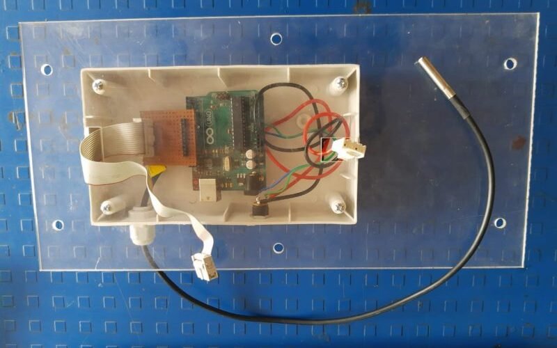
In order to protect the AHT sensor from dust and rain, a covering was designed and 3D printed.


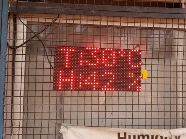
Test Run !!
The system was finally installed and monitored in Vigyan Ahsram
Troubleshooting and maintenance
The old system was successfully replaced with the new system and initially tested for 1 week. The system stopped working after a week. The reason for the failure was the low current supply from the adapter. The adapter was rated at 5V and 1A, and could not deliver enough current to the micro-controller as well as P10 led board. Therefore the adapter was replaced with a 5V and 2A adapter.
Regular cross checking of the system with available online data was carried out. It was observed that the device showed correct readings with minor deviations of <2OC in temperature and <5% deviation in humidity during the day. These deviations increased during the night when the temperatures were low. The reason for this inaccuracy was due to the heating up of the the P10 board, causing a change in the micro-environment of the device. To counter the problem the sensor along with the covering was placed away from the device to avoid inaccuracies.


