
- 2nd July, 2022
I’m working on Project of On-Grid Solar System Bypass Switching System
According to MNRE, In India grid-connected solar power plants have a total capacity of 28180.68 MW, but their effectiveness and Return on Investment (RoI) depend on a number of variables, including solar light intensity and their controllers. Another major issue with modern inverters is that they stop utilizing solar energy when the grid is cut for various reasons, including maintenance and safety concerns, etc.
Objective:
The purpose of bypassing the Electricity grid when grid is OFF (for any maintenance or other purpose) the power generation from PV side also stops so we loss lot of amounts of energy. so in this project I’m going to bypass system (when grid is OFF) to use it for Local load. (for e.g. Vigyan Ashram)
So, I’ve discussed the process flow with Dr. Arun Dixit and Mr. Prasad Patil Sir. From which we can understand basically how it is going to work and how inverter sense the Electricity Grid.
- 4th July, 2022
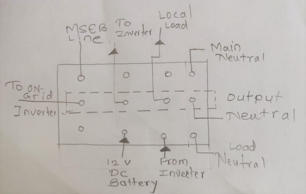
We have discussed how to manually do switching before going to do on Automatic Electronics based system. So I have suggested to use changeover with the following schematics diagram.
- 6th July, 2022 to 16th July, 2022
Read the installation manual and datasheet of Zeversolar Inverter installed at Memorial hall from online link below.
From the above manuals and datasheet I came to know that
Given Inverter is Transform-less Inverter
Grid Synchronization Circuit is available in Inverter to avoid
- Load Imbalance
- damage to connected equipment
- Instability in Grid
I have then started Searching about the protection circuit for the electricity to avoid flowing back when grid is OFF for any maintenance or other purpose the Term related to it is Anti Islanding Protection.
Anti-Islanding Protection with Grid-Tied PV Inverters – Yaskawa – Solectria Solar
Solar PV – Anti Islanding Safety Feature – YouTube
I have talked with Gram Oorja Engineer (who have installed Inverter at the place) Mr. Mahendra Chaurasiya they have shared me Electrical SLD of Vigyan Ashram Installation and Mr Prasad Kulkarni to discuss about this circuit and I have came to know that Voltage and Frequency are the Electrical Sensing Quantities.
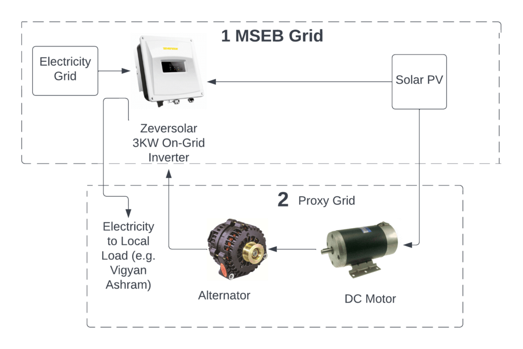
By doing literature survey on internet i came to know that one of the company is doing this by using Diesel Generator (DG) Set.
25th July, 2022
Brainstormed with Mr Vrushabh Zunzunkar, Dr Dixit Sir regarding selection of DC Motor and Alternator
From we’ve I came to know that DC Motor speed can controlled through Controllers.
We know that Faradays Law of Electromagnetic Induction,
E= -N dΦ/dt
where N = Number of Loops
dΦ= change in magnetic flux
dt= change in time
E= induced voltage
So we know voltage depends on number of loops in alternator and change in magnetic flux we can get constant voltage from this but we need to control speed of alternator (driven by DC Motor) to get 50Hz frequency.

Each solar panel has a DC voltage of 37.3 volts, and there are six of them connected in series to produce a voltage of 226.2 volts, which is directly fed to one of the Zeversolar On-Grid Solar Inverters.
Proof of Concept
- 1st August to 13th August, 2022
With Mr. Siddharth Kulkarni and Dr. Arun Dixit sir, we have begun talking about creating a DC motor and alternator design proof of concept. Therefore, we firstly require a high speed DC motor. We then choose to use a BLDC motor as an alternator, which is connected to the DC motor to produce alternating current. Finally, we are going to use a speed controller to control the RPM and an IR Sensor as an encoder to receive feedback on the speed.
by doing Discussion with Dr. Dixit sir and Mr. Siddharth Kulkarni and team we prioritized the task of researching actually how much power is required to give proxy grid to the zeversolar inverter and Is the line and load wires are actually on same line or different?
We’ve chosen to synthesise a DC motor alternator using a BLDC motor and a drill machine.

In this experiment we need to see that when BLDC is rotated the waveform generated is sine wave on CRO and having voltage of about 3.3mV. From this experiment we’ve gotten 40-45 Hz frequency with 0-550 rpm rated drill machine and frequency is changing w.r.t rpm of BLDC motor.
Conclusion


