
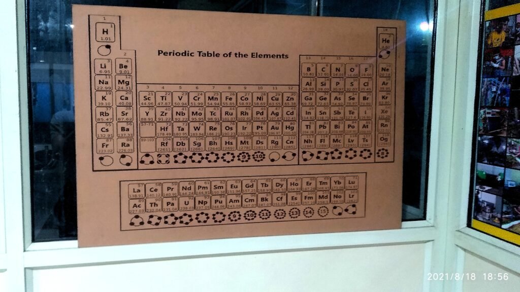
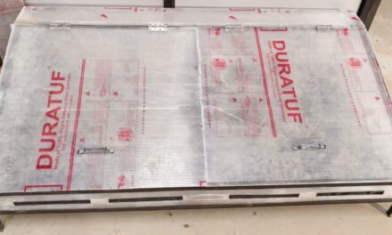
So welcome back, well I don’t know for what purpose you are peeking by, but here’s my experience working on the above MDF engraved periodic table, you will find it in the DIC lab, backside where Arun Sir sits.
Now why I kept the heading and content limited to converting image file to .dxf, which then goes to RD works after which it is converted to g-code to the specific laser cutter, is because my assignment with this was to help Prathemesh Big Bro to choosing-editing-converting to .dxf, such that he can then do the laser printing, so here I am sharing my experience.
To start with do not edit whatever image you are planing in drawing software like Krita, GImp, Paint etc. as the bit mapper in your Vector designing software will not perfectly trace the edits made. So first trace the image then do editing in vector design soft then export directly to .dxf, not like me who wasted 1 day fruitless, still I learned what not to do.
Then comes a brief discussion on Vector Designing/Drawing Software, with my experience working on Coral Draw, Then jumping to Inkscape, for the purpose of converting .jpeg/.gif to .dxf and a temp work where you don’t want to buy any packages go for Inkscape. It has a small learning curve then it should be smooth as butter to navigate the 3rd and forward time.
[why am I documenting the steps- I fear I will forget what I learned few months ahead so here is my memory repository which I and others can use!!!]
So with certain knows and how above let’s start-
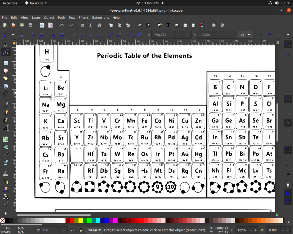
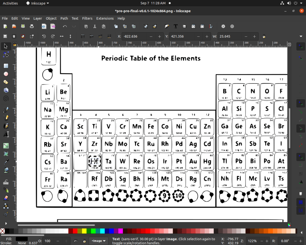
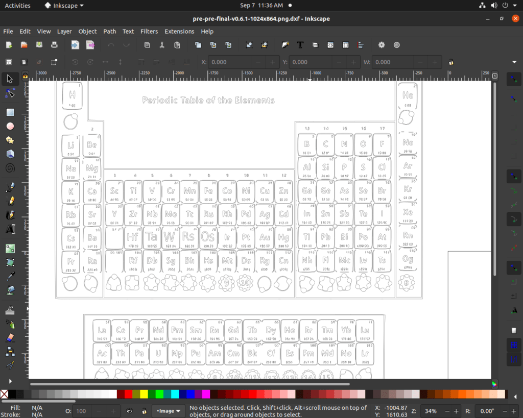
with step one in my case image of the periodic table-
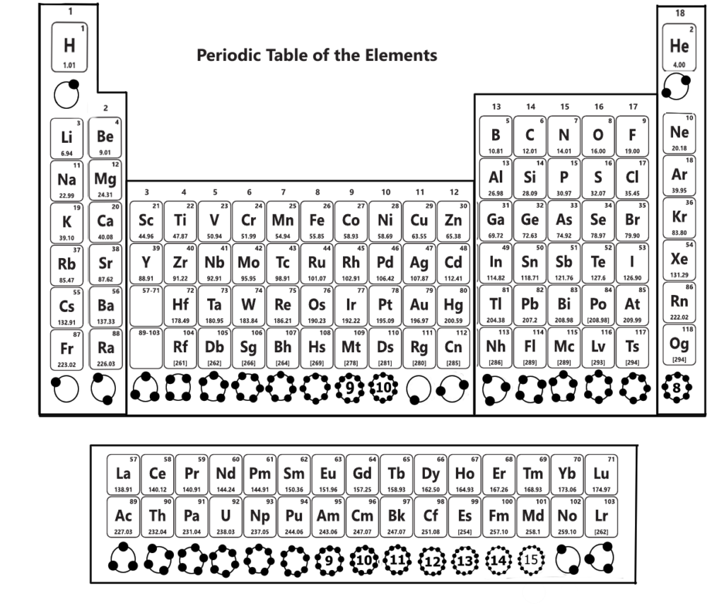
[The circles blow each group are the valance electron!, how I made them well using Krita I suggest don’t do it in my way rather make all the edits in InkScape that also after bit mapping the initial image.]
Once you have the desired pic to work on, here i would like to sum up the steps and then give detailed steps to the process. 1) Select the image -> 2) go to ‘Path’ -> 3) select ‘Trace Bitmap’ -> 4) will get dilague box choose your options as per intrest(Tinker around) -> 5) press ‘Apply’ in the dialogue box -> 6)close the dilague box -> 7) select the image and drag the bitmapped image out -> 8) setect ‘edit path by nodes -> 9) select the nodes you want to delete -> 10) once you have clean slate -> 11) choose ‘Text tool’ -> 12) enter new number/letter -> 13) once edits are done(inclusing resizing with select tool) -> 14) select the are/hole image on which edits are done -> 15) select ‘Text’ option-> 16) in the menue choose ‘Put on Path’ option -> 17) Go to ‘File’ option -> 18) select save and fist save with .svg ->19) select ‘File’ then save as with .dxf (Autodesk 14) -> 20)access you file in saved location.
Now let’s have a detailed kind of conversation- if anyone feels I skipped any step or missed any explanation, feel free to replay at any length in the comments.
1) Select the image—
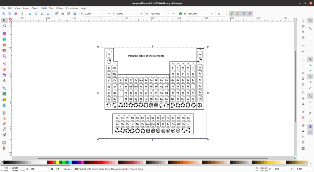
to select just drag the mouse holding the lift click on the mouse around your image, just drag over the complete image for best results.
2) go to ‘Path’ —

the select path from the top menu.
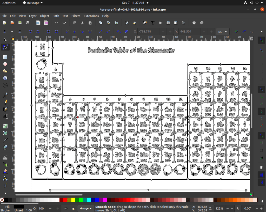
3) select ‘Trace Bitmap’—
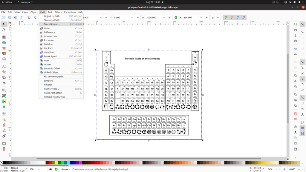
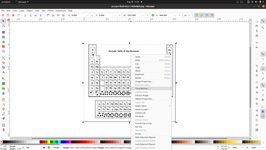
this can be done in 2 ways or the top menu path option or right mouse click options(img 2).
4) will get a dialogue box to choose your options as per interest(Tinker around)—
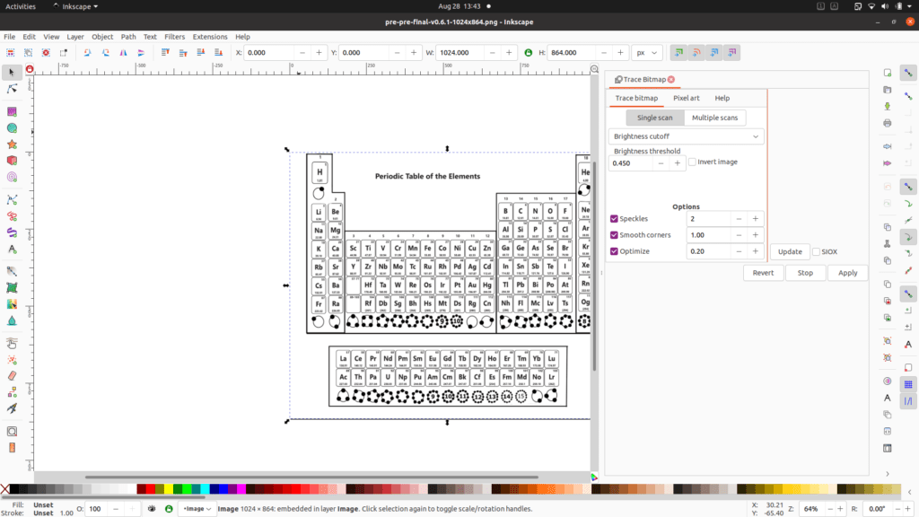
here I am extremely sorry as this option is well used with tinkering around at least for me, if anyone figures out the way to explain it, comment below or write a mail to -‘ srineevas2996@gmail.com ‘ I will update accordingly.
5) press ‘Apply’ in the dialogue box —-
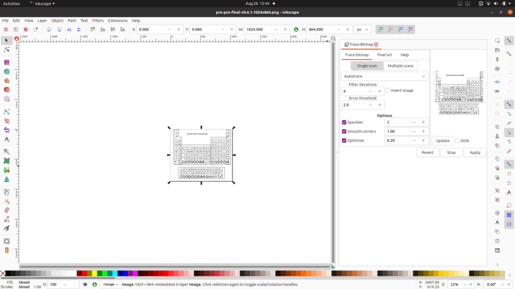
6)close the dialogue box -> 7) select the image and drag the bitmapped image out —
at this step, it’s not necessary to close the dialogue box, as it provides simultaneous ways to testing different configurations. but while dragging simply select the original image and drag the thing left click on.
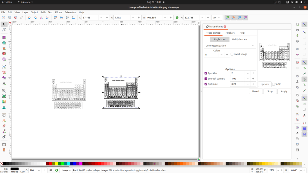
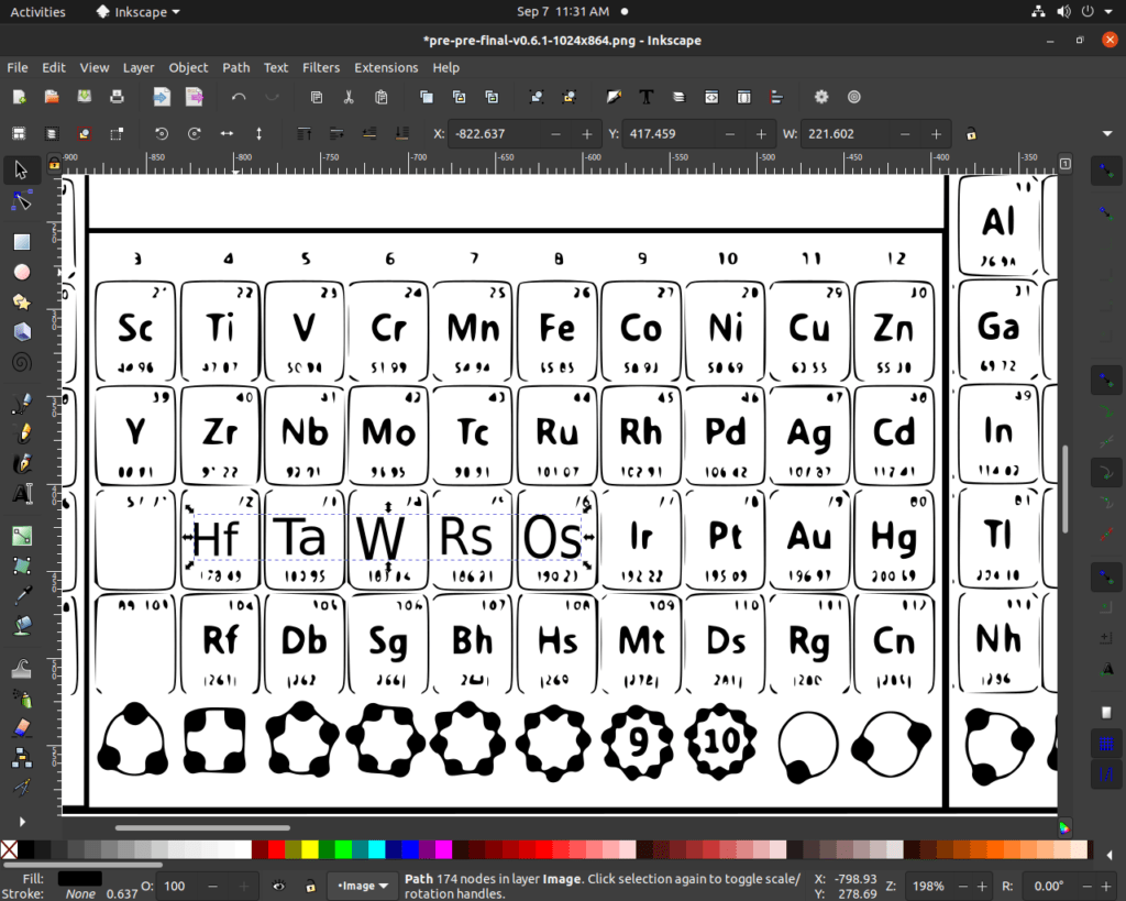
8) select the ‘edit path by nodes’ tool. —

9) select the nodes you want to delete—
select the part by dragging the mouse with the left click.
10) once you have clean slate -> 11) choose ‘Text tool’ -> 12) enter new number/letter —
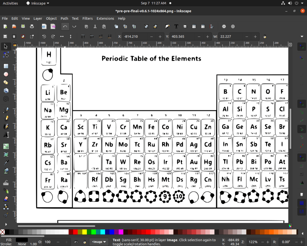
13) once edits are done(including resizing with select tool)—
here adjusting the characters need one to select, ‘edit and transform’ tool(one above path tool). One can choose the font style before typing but in my experience just typing first then editing its location and size later works much faster for me.
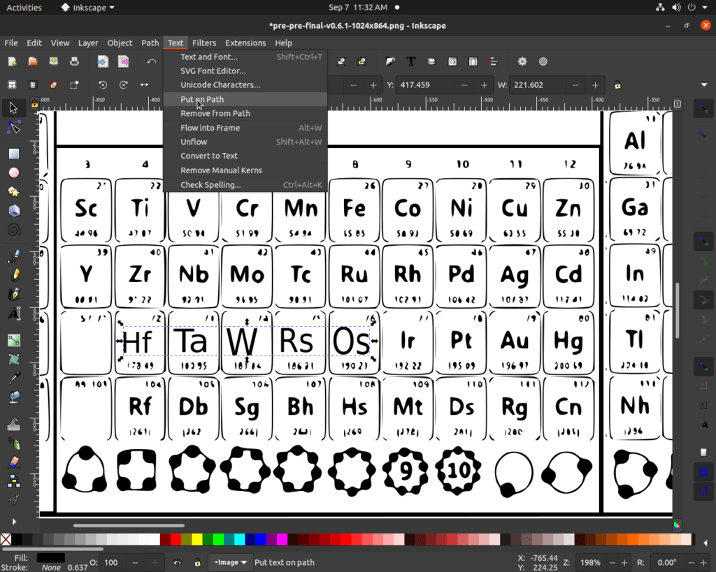
14) select the are/hole image on which edits are done—
15) select ‘Text’ option-> 16) in the menue choose ‘Put on Path’ option —
17) Go to ‘File’ option -> 18) select save and fist save with .svg—
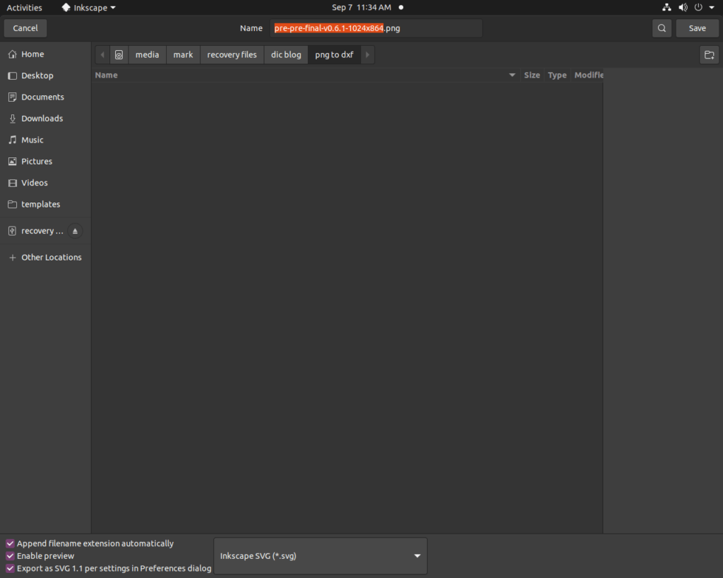
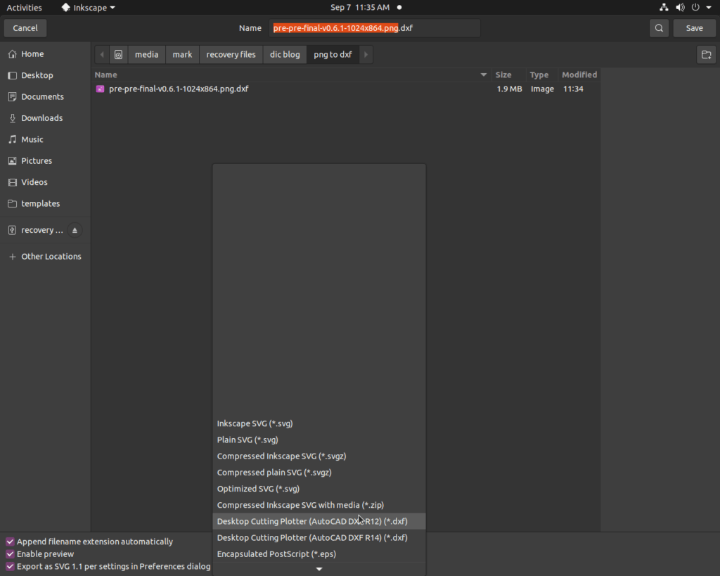
19) select ‘File’ then save as with .dxf (Autodesk 14) -> 20)access you file in saved location.—
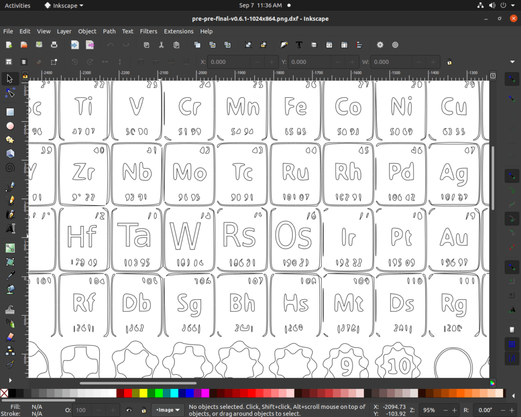
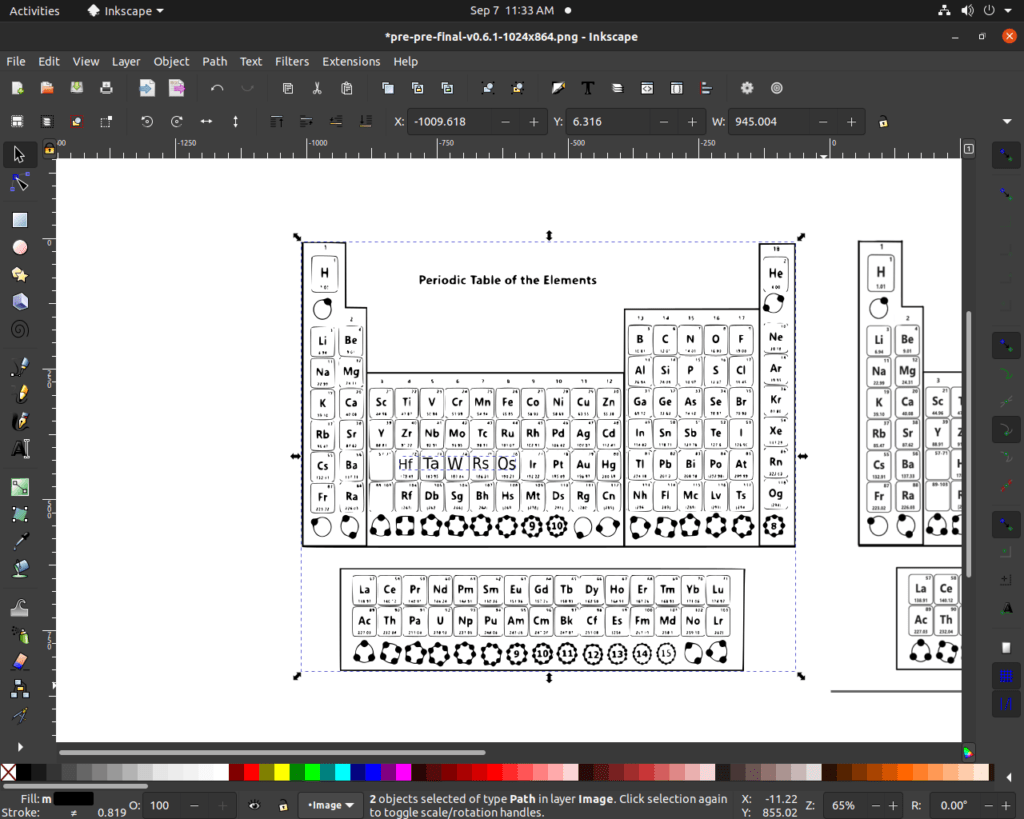
In this tut/art. I limited myself to few edits to save time, I hope the above pic tells you the difference. Not to mention the later cutter will replicate the same as you edited (style/font).
with this, I am completing this blog, hope it was useful, and thanks for reading, meet you in my next blog.

