Introduction:-
In today’s twentieth century, everyone has a habit of running away. Everyone is in a hurry and no one wants to stop So sometimes we forget some things. A job happens in everyone’s home. This is the work of filling the water tank, while doing this we start the water motor, but we forget to turn off the water motor. This story is not found in every household but everywhere. Like in hostels, hospitals, complexes, wherever there are water tanks, there is a noise. The tank is full Turn off the motor. The same thing was happening in our Vigyan Ashram. To get satisfaction from these things, we experimented with the bell ringing after filling the water tank. So you know the water tank is full.
Problem statement:–
- Once the water tank is full, some water is wasted.
- There is an increase in the electricity bill.
Objective:
- Water should not be wasted.
- Saving electricity.
Component:-
- Arduino Uno
- Float sensor
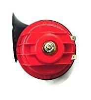
- Speaker (12v)
- adapter (5v)
- SMPS(12v 3a)
- Relay (5V)
Arduino Uno:-
The Arduino is an open-source electronics platform based on easy-to-use hardware and software used to build electronics projects. All Arduino boards have one thing in common which is a microcontroller. A microcontroller is basically a really small computer.

The Arduino boards are basically a tool for controlling electronics. They are able to read inputs with their onboard microcontroller (eg. Light on a sensor, an object near a sensor) and turn it into an output (Drive a motor, ring an alarm, turn on an LED, display information on an LCD).
Float sensor:-
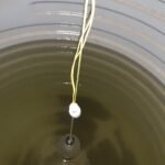
In short, a float switch is a mechanical switch that floats on top of a liquid surface. As the liquid level goes up or down, it moves vertically with the liquid level. Depending on the counterweight and pre-set ‘trigger’, the mechanical switch opens or closes allowing an electrical current through it to the connected device. Typically, this connected device either stops or starts the inflow of the liquid.

The float switch consists of a hollow floating body and an internal switch, also called a sensor. The most common internal switch is a reed switch, so there is also a magnet inside the body. There are other types of internal switches, but the working principle that they open/close due to gravity and water level moving the float switch vertically up or down is the same. Therefore, the mechanical switch creates an open or closed electrical circuit.
Realy:-
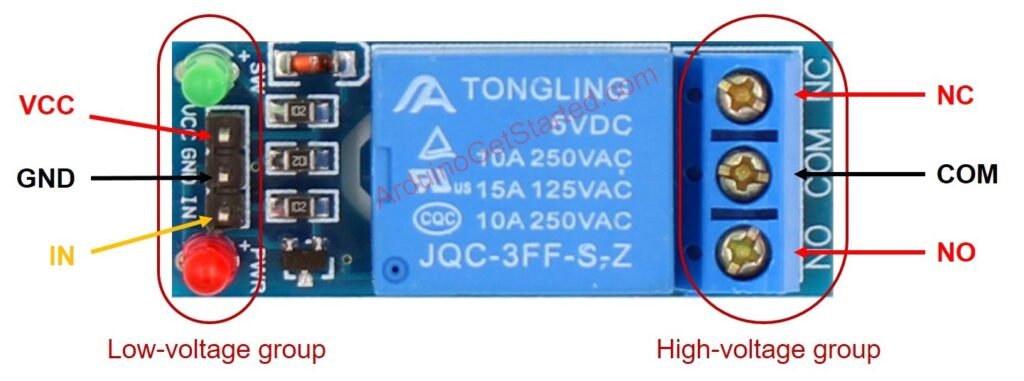
Relays are switches that open and close circuits electromechanically or electronically. Relays control one electrical circuit by opening and closing contacts in another circuit
Normally Open Contact (NO) – NO contact is also called a make contact. It closes the circuit when the relay is activated. It disconnects the circuit when the relay is inactive.
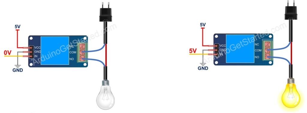
Normally Closed Contact (NC) – NC contact is also known as break contact. This is opposite to the NO contact. When the relay is activated, the circuit disconnects. When the relay is deactivated, the circuit connects.
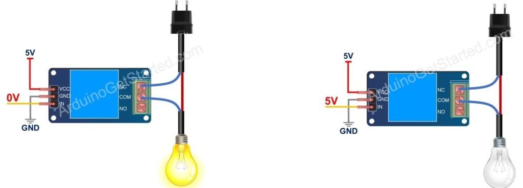
Change-over (CO) / Double-throw (DT) Contacts – These types of contacts are used to control two types of circuits. They are used to control a NO contact and also an NC contact with a common terminal. According to their type, they are called by the names break before make and make before break contacts.
SMPS:-
The power supply circuit plays an important role in every electrical and electronic circuit to supply power from the owl circuit to the computer and various machines. The full name of SMPS is Switch-Mode Power Supply.SMPS is defined in simple language when the need for electricity comes in the form of a switch. In which electrical energy is converted from one form to another with essential properties called SMPS.
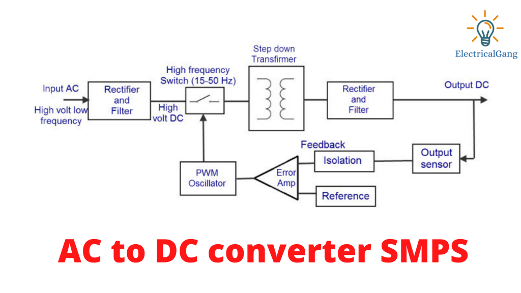
In this type of SMPS, the input supply is AC and in the output, we get DC supply. Rectifiers and filters are used to convert this AC power to DC. This uncontrollable DC voltage is given to the affected power factor correction circuits. This is because there is a low current pulse inside the rectifier around the peak of the voltage.
Speaker (12v) :-
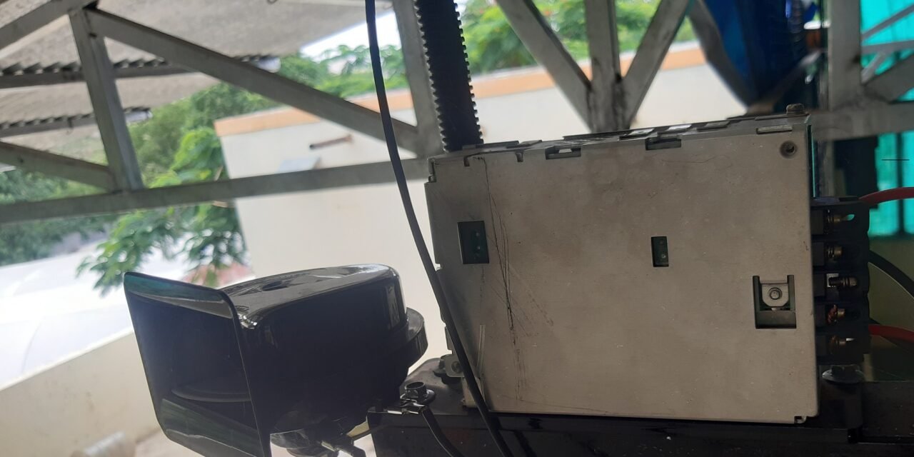
12v 3ah speaker is used for this project. The reason for installing this speaker is that when the water tank is full, everyone can hear its loud sound.
CIrcuit Digram:-

| Arduino | connecting pin |
| 5v | relay pin 5v |
| Gnd | relay pin Gnd |
| pin 8 | relay signal pin |
| pin 6 | float sensor(+) |
| Gnd | float sensor (-) |
| relay com pin | speaker |
| relay NC pin | SMPS (-) |
| SMPS(+) | Speaker |
Connect each of the components as shown in the figure and upload code in Arduino.
Code:-
#define relay 10
#define FS 11

int senstate;
bool x;

void setup() {
  Serial.begin(9600);

  // initialize digital pin 8 as an output.
  pinMode(relay, OUTPUT);
  pinMode(FS, INPUT_PULLUP);
  digitalWrite(relay, HIGH);
  x=false;
}

void loop() {
  senstate  = digitalRead(FS);

  if (senstate == 1)
  {
    if (x)
    {
      digitalWrite(relay, HIGH);
      delay(500);
      digitalWrite(relay, LOW);
      delay(1000);
      digitalWrite(relay, HIGH);
      delay(500);
      digitalWrite(relay, LOW);
      delay(500);
      digitalWrite(relay, HIGH);
      delay(500);
      digitalWrite(relay, LOW);
      delay(500);
      digitalWrite(relay, HIGH);
      delay(500);
      digitalWrite(relay, LOW);
      delay(500);
      digitalWrite(relay, HIGH);

      x = false;
      Serial.println("STEP ONE DONE");
    }


  }

  else if (senstate == 0)
  {
    if (!x)
    {
      digitalWrite(relay, HIGH);
      x = true;
      Serial.println("STEP TWO DONE");
    }


  }
  delay(1000);
}
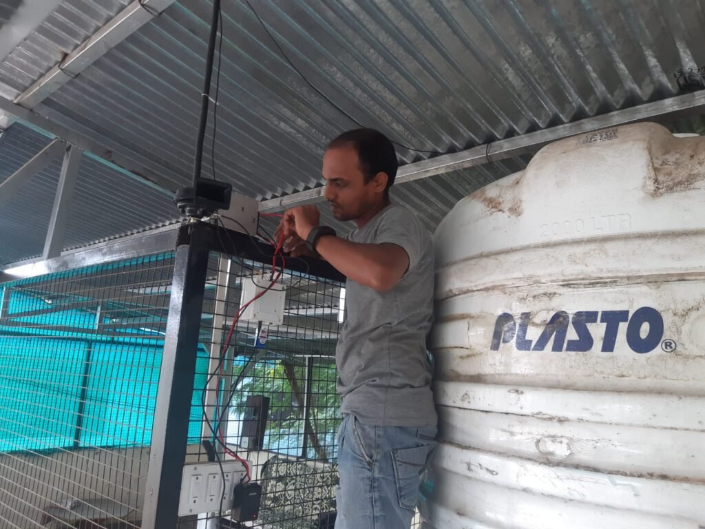
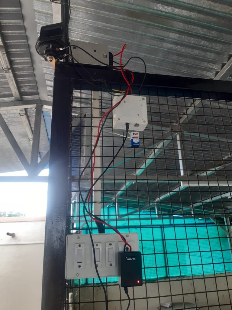
Making a casing for the control unit uses the junction box and install setup. float sense deep in the water tank.
There were some difficulties while preparing this project
- loose connection
- code error
- proper dc adapter
Reference:-
https://arduinogetstarted.com/tutorials/arduino-relay

