PROBLEM STATEMENT:
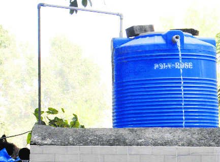
Need of this project is to avoid wastage of water.Because sometimes people forget to off the motor when tank is full,because of that water get wasted.To avoid this problem this project came into picture.By using this water level indicator system we can monitor water level and consumption of water.
OBJECTIVE:
Water level indicator with monitoring will develop considering fulfillment of following objective:
kitchen system with actuator,level indicator for UV water purifier.
Ladies hostel water tank with actuator ,water level indicator,monitoring using pump.
To log data of water consumption in ladies hostel.
To get alarm using GSM module whenever tank is full.
INTRODUCTION:
In this Arduino based automatic water level indicator and controller project we are going to measure the water level by using ultrasonic sensors. Basic principal of ultrasonic distance measurement is based on ECHO. When sound waves are transmitted in environment then they return back to the origin as ECHO after striking on any obstacle.
So we have to only calculate its travelling time of both sounds means outgoing time and returning time to origin after striking on any obstacle. And after some calculation we can get a result that is the distance. This concept is used in our water controller project where the water motor pump is automatically turned on when water level in the tank becomes low.
COMPONENT REQUIRED:
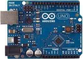
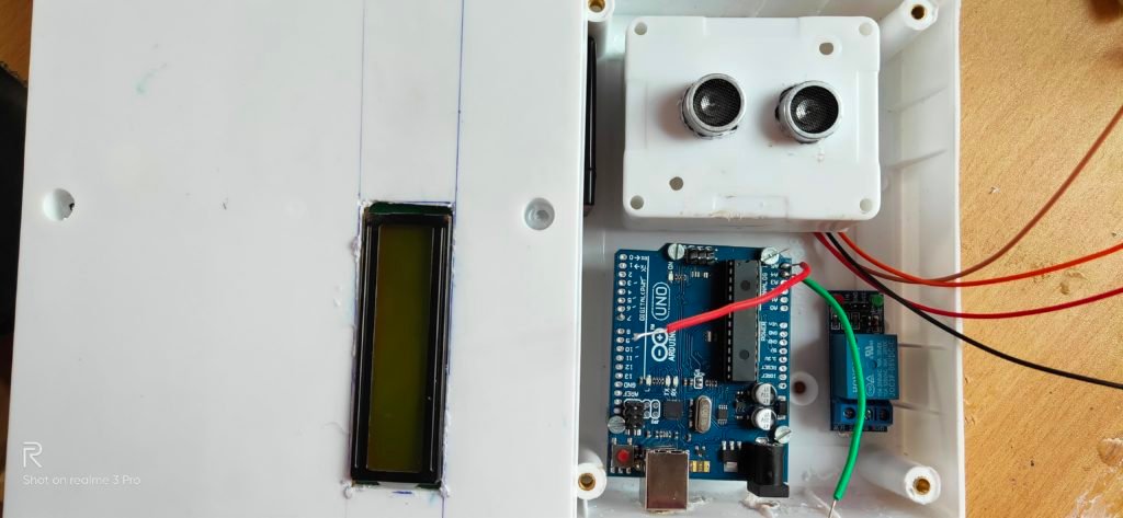
Arduino Uno: Arduino Uno is a microcontroller board based on the ATmega328P. It has 14 digital input/output pins (of which 6 can be used as PWM outputs), 6 analog inputs .Operating voltage is 5V.
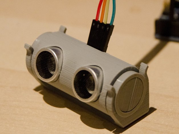
Ultrasonic sensor module:The ultrasonic sensor uses sonar to determine the distance to an object. Here’s what happens:
1.The transmitter (trig pin) sends a signal: a high-frequency sound.
2.When the signal finds an object, it is reflected and…
3… the transmitter (echo pin) receives it.

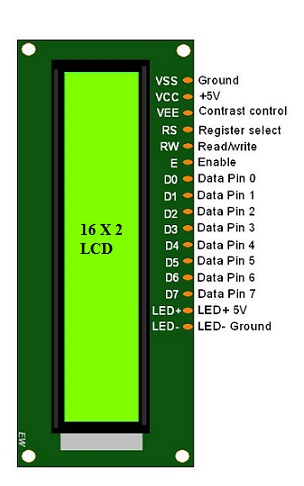
16X2 LCD :
The operating voltage of this LCD is 4.7V-5.3V
It includes two rows where each row can produce 16-characters.
The utilization of current is 1mA with no backlight
Every character can be built with a 5×8 pixel box
The alphanumeric LCDs alphabets & numbers
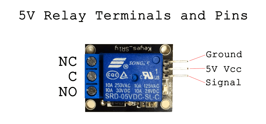
5 volt relay: Relay has three high voltage terminals (NC, C, and NO) which connect to the device you want to control. The other side has three low voltage pins (Ground, Vcc, and Signal) which connect to the Arduino.
Connecting Wires:Wires are used for connecting the components.
Enclosure: Enclosure is required to provide safety for the components.
COSTING OF COMPONENT:
All components are purchased from Trio Radio and Electronics, Pune
| Components | Price |
| Arduino Uno | 450 |
| Ultrasonic Sensor | 100 |
| LCD display | 120 |
| I2C module | 70 |
| Relay module | 70 |
| Battery | 220 |
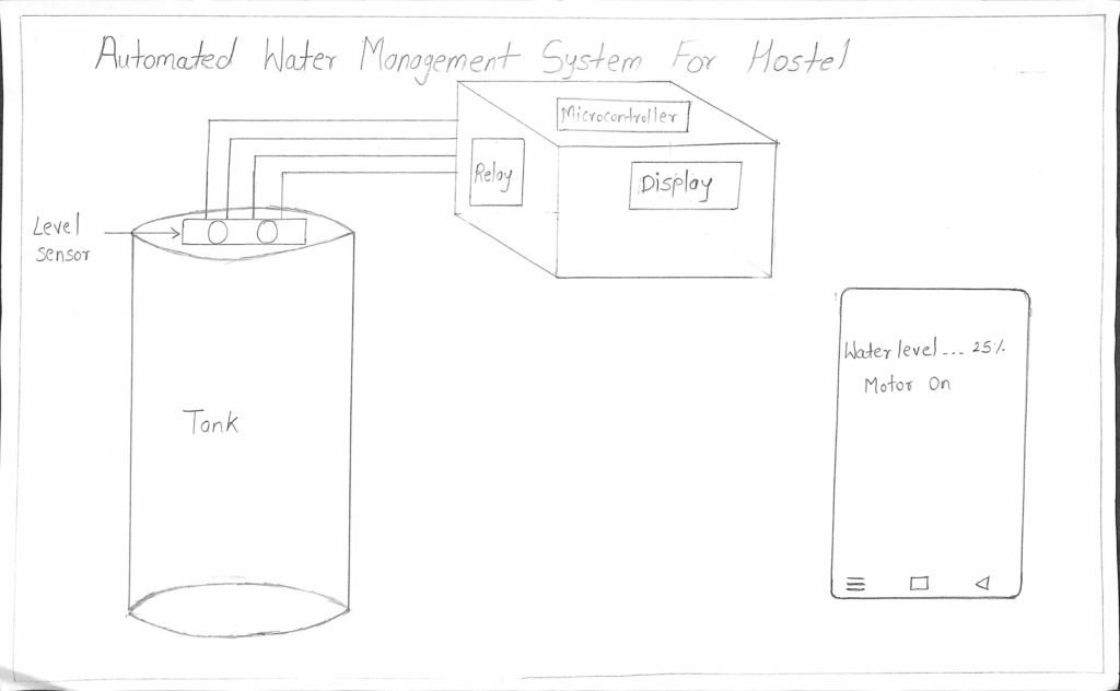
BLOCK DIAGRAM:
WORKING:
Working of this project is very simple I have used Ultrasonic sensor module which sends the sound waves in the water tank and detects reflection of sound waves that is ECHO. First of all I need to trigger the ultrasonic sensor module to transmit signal by using Arduino and then wait to receive ECHO. Arduino reads the time between triggering and received ECHO. We know that speed of sound is around 340 m/s. so we can calculate distance by using given formula:
Distance= (travel time/2) * speed of sound
Where speed of sound is approximately 340m per second.
By using this methods we get distance from sensor to water surface. After it we need to calculate water level.
Now we need to calculate the total length of water tank. As we know the length of water tank then we can calculate the water level by subtracting resulting distance coming from ultrasonic from total length of tank. And we will get the water level distance. Now we can convert this water level in to the percent of water, and can display it on LCD.
CODING:
#include <LiquidCrystal.h>
#include <LiquidCrystal_I2C.h>
LiquidCrystal_I2C lcd(0x27,16,2);
#define trigger 10
#define echo 11
#define motor 8
#define buzzer 12
//LiquidCrystal lcd(7,6,5,4,3,2);
const int numRows = 2;
const int numCols = 16;
float time=0,distance=0;
int temp=0;
void setup()
{
   lcd.init();
 lcd.backlight();
 lcd.begin(16,2);
 lcd.begin(numCols, numRows);
 pinMode(trigger,OUTPUT);
 pinMode(echo,INPUT);
 pinMode(motor, OUTPUT);
 pinMode(buzzer, OUTPUT);
 lcd.print("  Water Level ");
 lcd.setCursor(0,1);
 lcd.print("   Indicator  ");
 delay(2000);
}
void loop()
{
 lcd.clear();
 digitalWrite(trigger,LOW);
 delayMicroseconds(2);
 digitalWrite(trigger,HIGH);
 delayMicroseconds(10);
 digitalWrite(trigger,LOW);
 delayMicroseconds(2);
 time=pulseIn(echo,HIGH);
 distance=time*340/20000;
 lcd.clear();
 lcd.print("Water Space In  ");
 lcd.setCursor(0,1);
 lcd.print("Tank is: ");
 lcd.print(distance);
 lcd.print("Cm");
 delay(2000);
 if(distance<12 && temp==0)
 {
     digitalWrite(motor, LOW);
     digitalWrite(buzzer, HIGH);
     lcd.clear();
     lcd.print("Water Tank Full ");
     lcd.setCursor(0,1);
     lcd.print("Motor Turned OFF");
     delay(2000);
     digitalWrite(buzzer, LOW);
     delay(3000);
     temp=1;
 }
  else if(distance<12 && temp==1)
 {
     digitalWrite(motor, LOW);
     lcd.clear();
     lcd.print("Water Tank Full ");
     lcd.setCursor(0,1);
     lcd.print("Motor Turned OFF");
     delay(5000);
 }
 else if(distance>30)
 {
   digitalWrite(motor, HIGH);
   lcd.clear();
   lcd.print("LOW Water Level");
   lcd.setCursor(0,1);
   lcd.print("Motor Turned ON");
   delay(5000);
   temp=0;
 }
}
ADVANTAGES:
Power saver
Save money by using less electricity and water
Sends an alert to let you know water is too high or too low
Automatically adjusts water levels
APPLICATIONS:
Can be used in factories, commercial complexes, apartments, home.
Fuel tank level gauging.
Automatically turn ON/OFF pumps .
Irrigation control .
V2. Automated Water Management System
What does mean by Automated water management system?In Vigyan Ashram,we have water scarcity issues because PABAL is drought prone region.
So how to stop water wastage issue?This topic discussed with our director Yogesh Kulkarni Sir and with Dixit Sir. In discussion we discussed various solution ,problems and how we will work on it.
How our solution is effective than others solutions? Also how much this project is important in rural area or in any sector,these all points are discussed in our discussion.
My colleague Pooja did project on Dam Water Level Indicator.In this project she worked on indication of water level in dam.
It mean how much water is remaining in Dam is displayed on display. With reference to this project I have extended my project as I will keep data log of water consumption and display of water level.
And also I have to on and off motor when tank is full or empty. I have to send message on mobile when water level is reached to 100% or when water level is fully low.
I discussed my project with our instructor Suhas Sir and Aditi. From discussion I understood what I have to do. According to this I started thinking on my project.What are input devices , what are output devices ,which controller should I use?These questions came into mind. So I started working on schematic of project and I have studied different controller.
I will just give idea ,what I will going to do.In Vigyan Ashram ,there are number of tanks and to monitor each tank is difficult task.
One specific person is required to monitor all tanks or to on or to make motor on or off.So to solve this problem,I am working on this project.
What I will do is I will sense water level by using water level sensor and that data will displayed on display and how much water is used that data will stored on cloud.Because of this no person will required to monitor the system.
I have given idea of project by drawing sketch.Sketch gives idea about which components are required for my project.
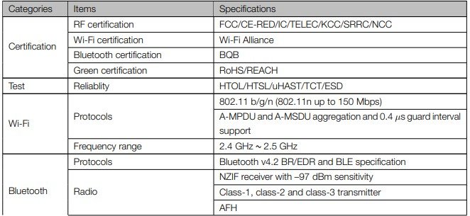
I read datasheet of ESP32 because it has inbuild wifi and bluetooth model. It has more advantage than other controller. I have to make mobile application for receiving message on mobile that tank is full or not.
♦Features of ESP32:♦
CPU: Xtensa dual-core (or single-core) 32-bit LX6 microprocessor, operating at 160 or 240 MHz and performing at up to 600 DMIPS.
Ultra low power (ULP) co-processor.
Memory: 520 KiB SRAM.
Wi-Fi: 802.11 b/g/n
Bluetooth: v4.2 BR/EDR and BLE (shares the radio with Wi-Fi)
12-bit SAR ADC up to 18 channels
2 × 8-bit DACs
10 × touch sensors (capacitive sensing GPIOs)
4 × SPI
2 × I²S interfaces
2 × I²C interfaces
3 × UART
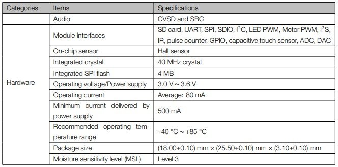
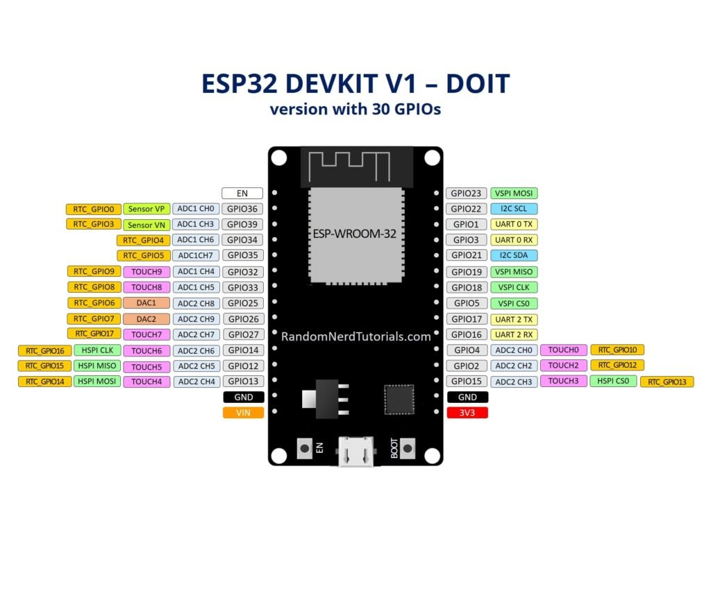
NOTE:ESP32 required only 3.3v supply.Dont give 5v directly to ESP32. It will burn out.For that you need regulator IC. If you have 3.3v supply then you can directly give it to 3v pin.
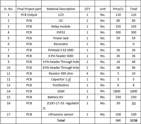
♦Project Material:♦
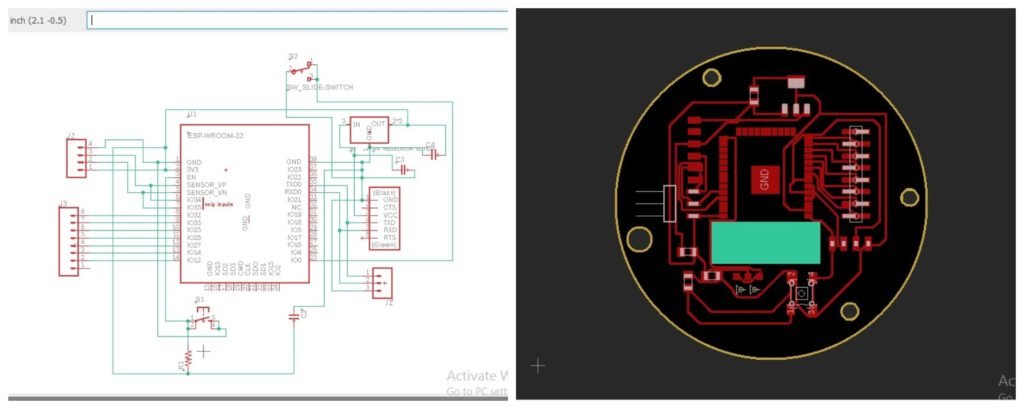
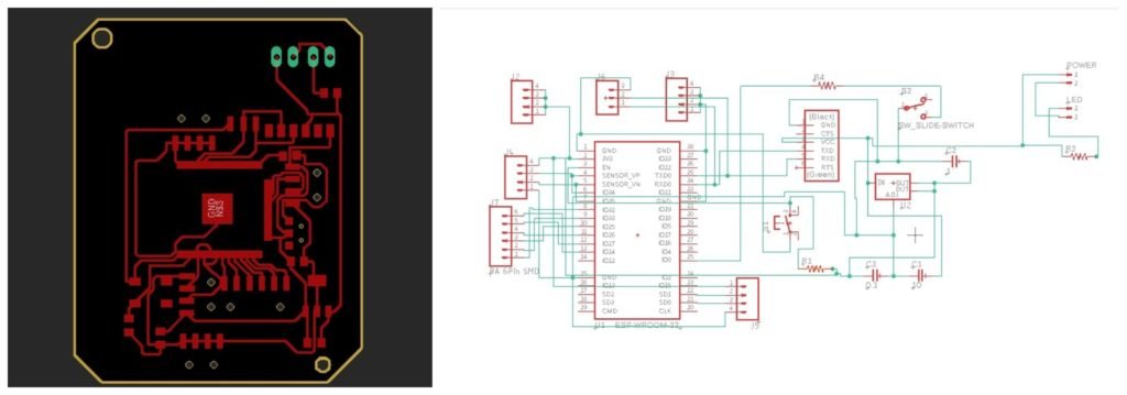
♦Electronic Design:♦
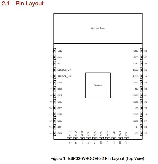
After study of ESP32 I started thinking of pcb design.Already Neil has given basic schematic of ESP32. For my final project board I need to add input and output devices ,so I need to design new board for that.
So I started design of my new board which include input ,output device.In input device I need ultrasonic sensor. For output device I required OLED. For this I required pin header. In eagle I required SMD pin header library,so I added library from sparkfun.
Also I need ESP32 library,but in FAb library I didnt found library for ESP32.
I started searching for library on github. I downloaded various ESP32 library.
First I made schematic and made pcb board.After that I milled that board. After milling I get to know that I have selected wrong footprint for ESP32.
All pins of ESP32 get short.I get so confused in ESP32 footprint. I didnt understand which one is correct footprint.
😕 😕 😕 😕 😕 😕 😕 😕 😕 😕 😕 😕
I decided to check footprint by milling it only .For that I milled 4 to 5 Pcb and I get all ESP32 pins short.
I searched previous student sites ,I didnt get any input from that.
I get so frustated ,then I decided to raise this question in issue tracker.
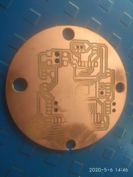
Again I designed new pcb using different footprint and milled it.Result of this pcb is also same as previous one. At the time of milling that pcb is not stick properly.After half milling it moved from original position.Because of this Pcb get wasted.
Again I made new design and tested whether it is making correct footprint or not ,but still I failed .Then I searched lot of possibilities why that footprint getting short.and I got the answer.Pad size of that footprint is large because of this 1/64 bit can’t trace that path.
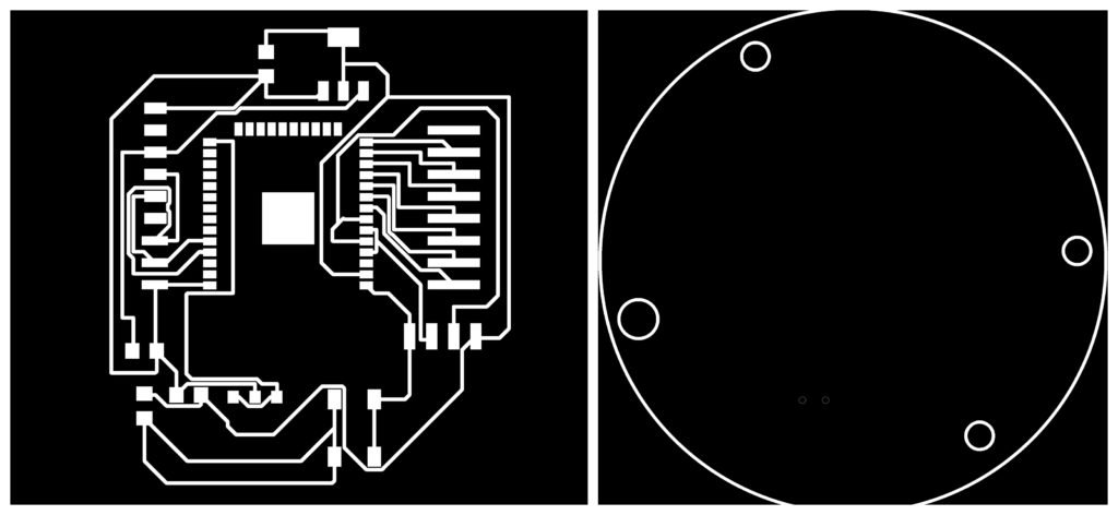
After searching on various site I got the solution .I changed pad size of that footprint and tested .Now its working fine.
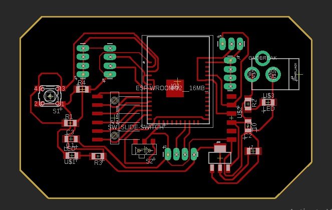
This is the final Board of my project,which I will mill on SRM-20 pcb milling machine.
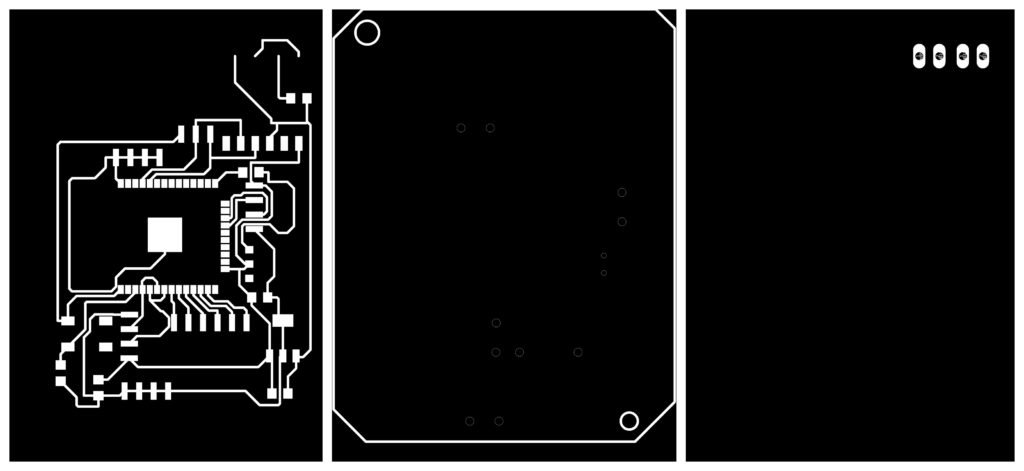
Mechanical Design:
To place all component in one box ,I required casing for that.I designed basic drawing of casing in freecad software.


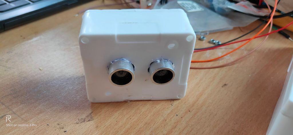
To prevent ultrasonic sensor from water I am going to make 3D casing for that.