Smart Grain Storage Monitoring System
Student Name: Krushna Sunil Mahajan
Project Introduction
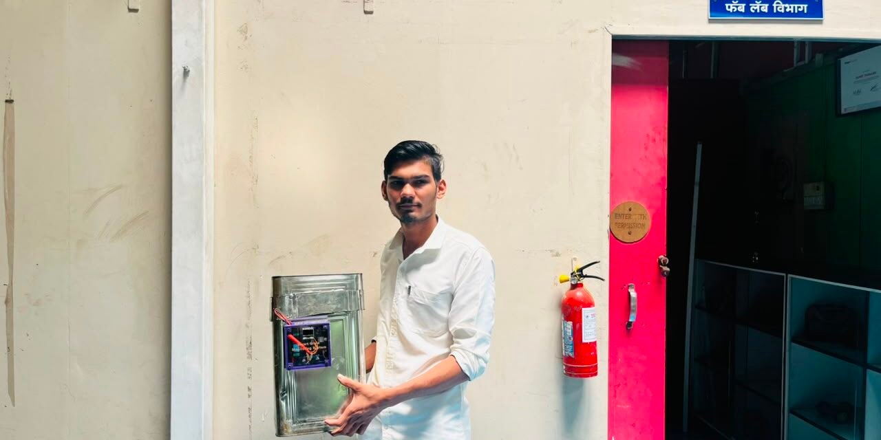
The Smart Grain Storage Monitoring System is an IoT-based monitoring and automatic control system designed to monitor the environmental conditions inside a grain storage area.
I developed this project using the XIAO ESP32-C3, DHT22 temperature and humidity sensor, 0.96-inch OLED display, relay module, DC fan, and LED.
The DHT22 continuously measures the temperature and humidity inside the grain storage area. The measured values are displayed on the OLED screen. When the humidity rises above 81%, the XIAO ESP32-C3 automatically activates the relay. The relay turns ON the DC fan and the red LED, indicating that the humidity level is high.
The main purpose of this project is to provide a simple automatic monitoring and ventilation system that can help maintain suitable environmental conditions during grain storage.
Problem Statement
Grains need suitable environmental conditions for safe and long-term storage. High humidity inside a grain storage area can increase the risk of moisture-related problems and may affect the quality of stored grains.
In a traditional grain storage system, temperature and humidity are often checked manually. If the humidity becomes high, the user may not immediately notice the problem.
Therefore, I wanted to develop a system that could:
- Continuously monitor temperature and humidity
- Display the readings in real time
- Detect high humidity automatically
- Turn ON a ventilation fan when humidity becomes high
- Provide an LED indication
- Reduce the need for continuous manual monitoring
To solve this problem, I developed the Smart Grain Storage Monitoring System using the XIAO ESP32-C3 and DHT22 sensor.
Proposed Solution
To solve the problem, I developed an automatic grain storage monitoring system using the XIAO ESP32-C3 as the main controller.
The DHT22 sensor measures the temperature and humidity inside the storage area. The XIAO ESP32-C3 receives the sensor readings and displays them on the 0.96-inch OLED display.
A relay is used to control the DC fan. When the humidity rises above 81%, the ESP32-C3 activates the relay. The relay turns ON the DC fan and the red LED.
When the humidity returns to the normal range, the relay and fan can be switched OFF.
This provides automatic monitoring and ventilation control for the grain storage environment.
Working Principle
The Smart Grain Storage Monitoring System continuously monitors the temperature and humidity inside the grain storage area.
The DHT22 sensor measures the environmental conditions and sends the data to the XIAO ESP32-C3.
The ESP32-C3 processes the sensor data and displays the temperature and humidity on the OLED display.
The controller continuously checks the humidity value against the programmed threshold of 81%.
Normal Condition
When the humidity is 81% or below:
Relay OFF → Fan OFF → Red LED OFF
High Humidity Condition
When the humidity becomes greater than 81%:
Relay ON → Fan ON → Red LED ON
The fan provides ventilation to help manage the high-humidity condition inside the grain storage area.
The basic system flow is:
DHT22 Sensor → XIAO ESP32-C3 → OLED Display
and
DHT22 Sensor → XIAO ESP32-C3 → Relay → DC Fan
The red LED provides a visual indication whenever the humidity crosses the selected threshold.
Block Diagram
The XIAO ESP32-C3 acts as the main controller of the system.
The DHT22 sensor provides temperature and humidity data to the controller. The OLED display shows the measured values. Based on the humidity level, the ESP32-C3 controls the relay.
The system flow is:
DHT22 → XIAO ESP32-C3 → OLED Display
XIAO ESP32-C3 → Relay → DC Fan
XIAO ESP32-C3 → Red LED
Pin Connections
| Component | XIAO ESP32-C3 Pin |
|---|---|
| DHT22 DATA | D2 |
| OLED SDA | D4 |
| OLED SCL | D5 |
| Relay IN | D3 |
| Red LED | D6 |
| DHT22 VCC | 3.3V |
| DHT22 GND | GND |
| OLED VCC | 3.3V |
| OLED GND | GND |
| Relay VCC | According to relay module |
| Relay GND | GND |
The red LED is connected through a suitable resistor for current limiting.
Expected Outcome
The expected outcome of this project is to develop a compact and working smart grain storage monitoring system.
The final system should:
- Measure temperature and humidity continuously
- Display the readings on the OLED
- Detect humidity above 81%
- Automatically activate the relay
- Turn ON the DC fan
- Turn ON the red LED
- Provide an easy visual indication of high humidity
- Help monitor environmental conditions in grain storage
- Work reliably on the final PCB
Project Development
After deciding the idea and basic requirements of the Smart Grain Storage Monitoring System, I started developing the project step by step.
The complete development process was carried out through the following stages:
Research → Components Ordering → Breadboard Testing → Sensor Testing → OLED Testing → Coding → Debugging → Relay Testing → Fan Testing → PCB Design → PCB Milling → PCB Testing → Component Assembly → 3D Design → 3D Printing → Final Assembly → Final Testing
Step 1 – Research
I started the project by researching the problems associated with grain storage and the importance of monitoring temperature and humidity.
I studied different sensors, microcontrollers, displays, relay modules, and ventilation systems that could be used to monitor and control the storage environment.
After comparing the requirements, I selected the XIAO ESP32-C3 as the main controller because of its compact size and suitable processing capabilities.
I selected the DHT22 sensor to measure temperature and humidity.
For displaying the sensor readings, I selected a 0.96-inch I2C OLED display.
A relay and DC fan were selected to provide automatic ventilation when the humidity becomes high
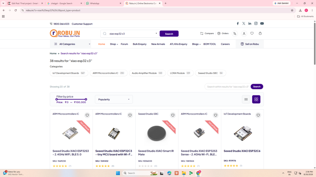
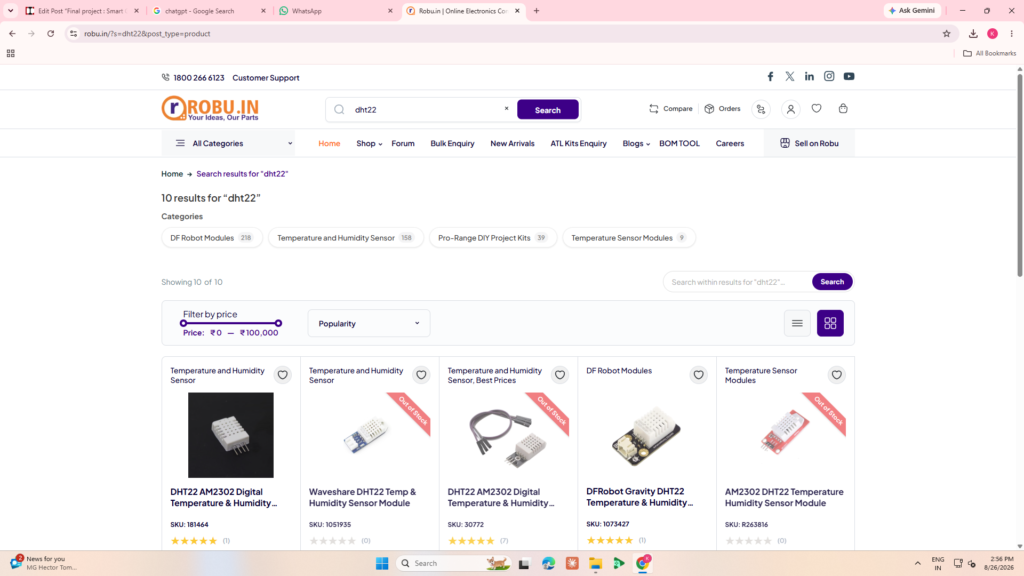
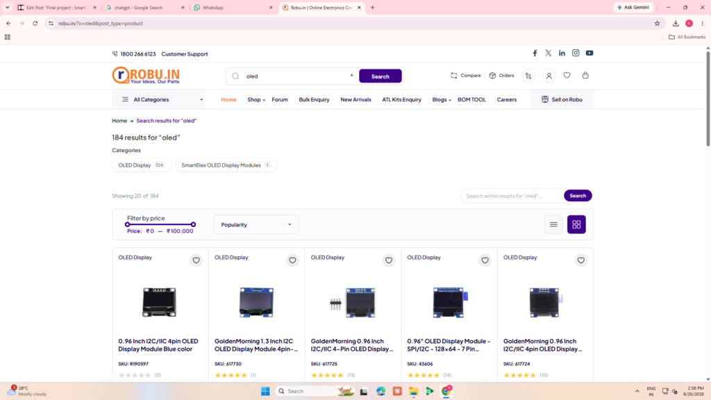
.
Step 2 – Components Ordering
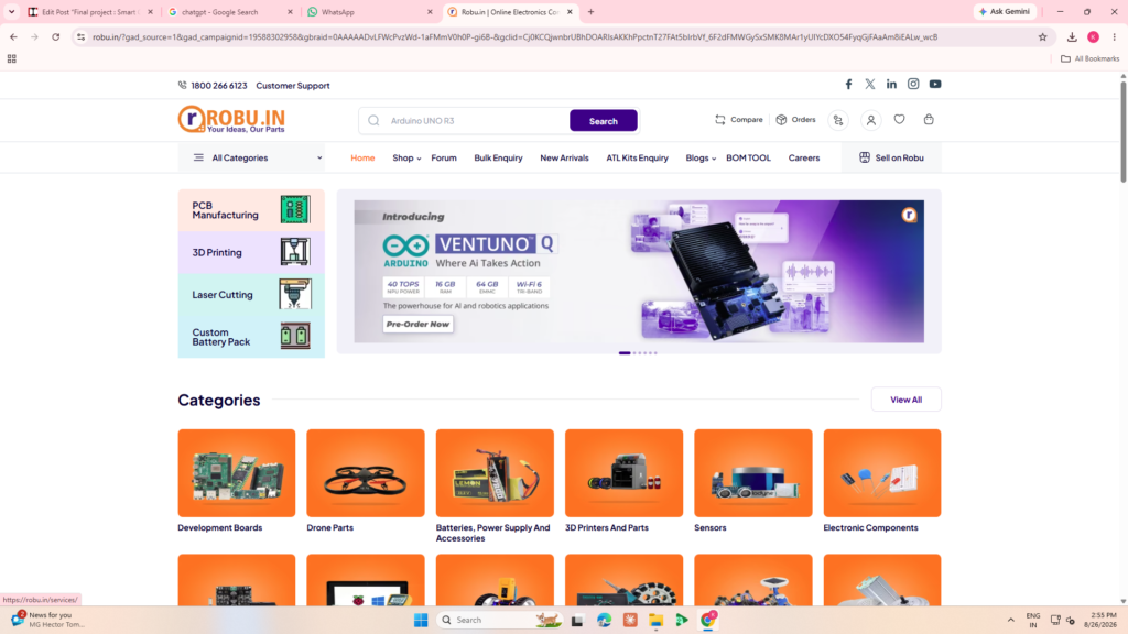
After completing the initial research, I finalized and ordered the components required for the project.
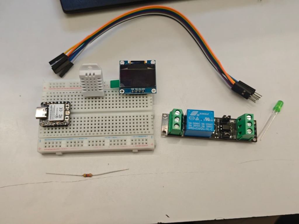
The main components included:
- XIAO ESP32-C3
- DHT22 temperature and humidity sensor
- 0.96-inch OLED display
- Relay module
- DC fan
- Red LED
- Resistor
- Connectors
- Wires
- Power supply
The components were selected according to the planned circuit and project requirements.
Step 3 – Breadboard Testing
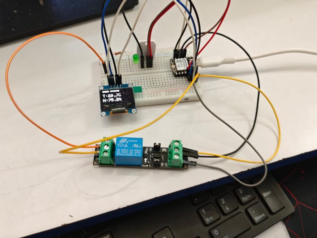
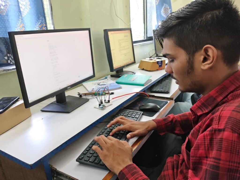
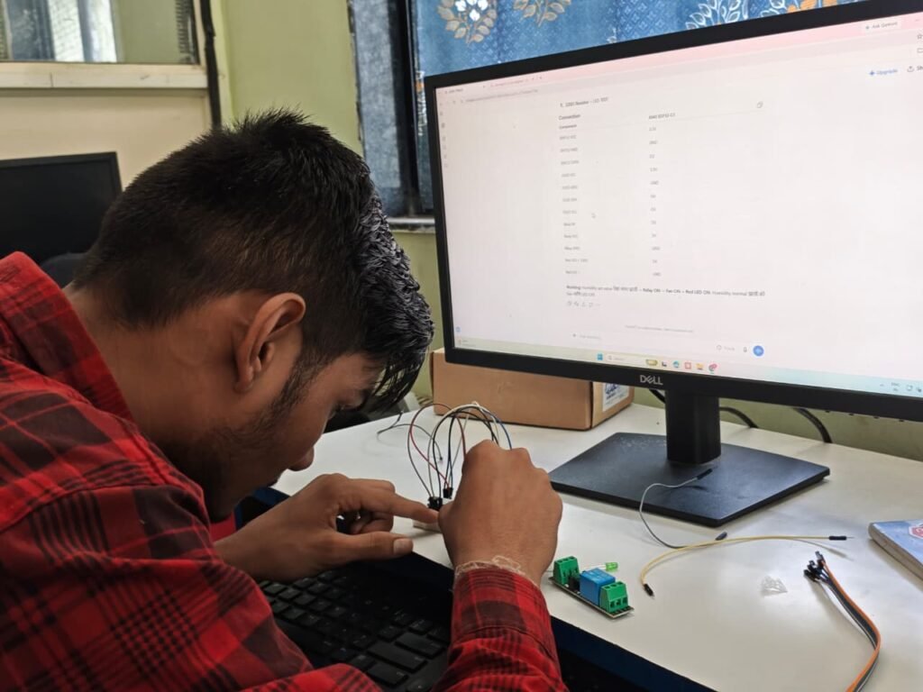
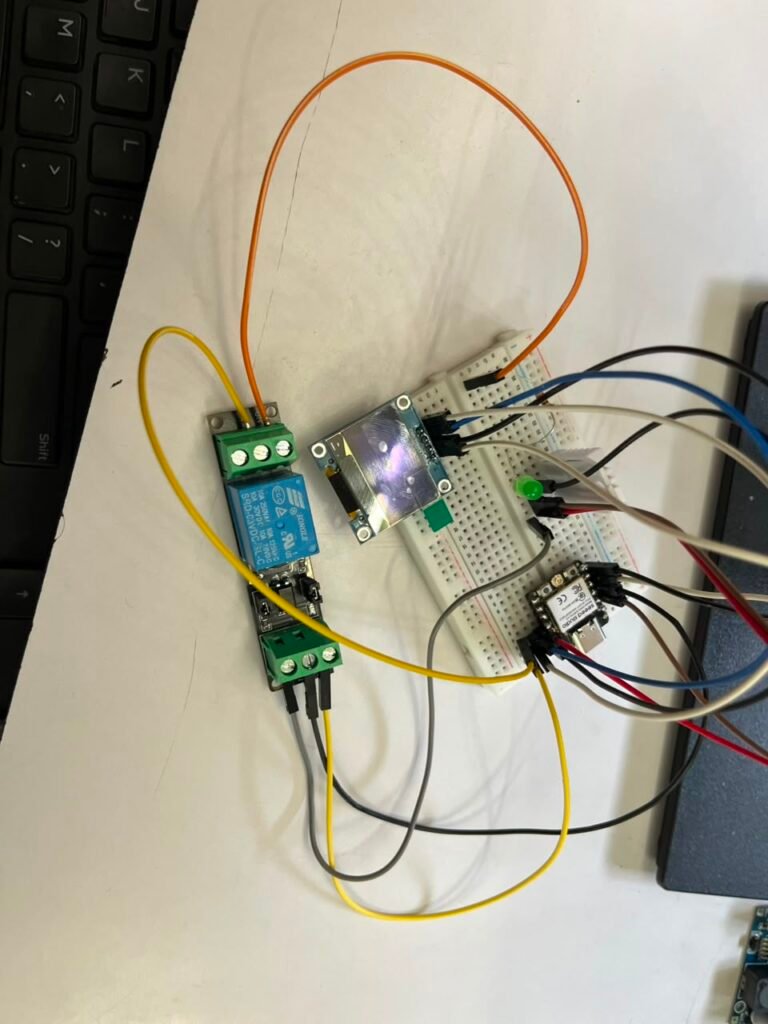
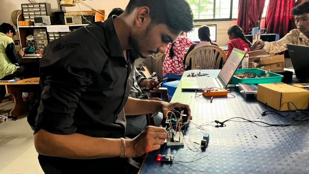
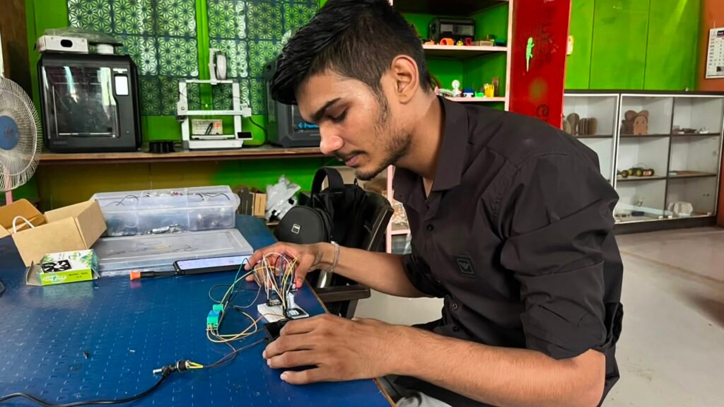
After receiving the components, I started testing the project on a breadboard.
First, I connected the DHT22 sensor to the XIAO ESP32-C3 and checked whether the temperature and humidity readings were received correctly.
After successfully reading the sensor values, I connected the OLED display and displayed the temperature and humidity readings.
Next, I connected the relay and red LED.
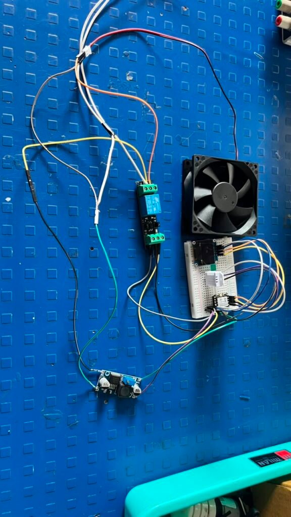
Finally, I connected the DC fan through the relay and tested the automatic control operation.
Testing the circuit on a breadboard helped me identify connection and programming problems before moving to the final PCB.
Step 4 – Coding and Testing
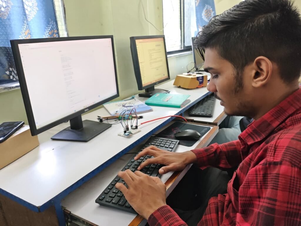
After completing the basic breadboard connections, I started developing the firmware using Arduino IDE.
The first program was developed to read temperature and humidity values from the DHT22.
The readings were then displayed on the OLED.
I tested the basic functions to make sure that:
- The DHT22 was reading correctly
- Temperature was displayed
- Humidity was displayed
- OLED was working correctly
- XIAO ESP32-C3 was communicating correctly with the sensor
After successfully testing these functions, I added the relay and LED control.
Step 5 – High Humidity Detection
After successfully displaying the sensor readings, I added the automatic humidity detection logic.
The humidity threshold was set to 81%.
The system operates according to the following condition:
Humidity ≤ 81% → Relay OFF → Fan OFF → Red LED OFF
Humidity > 81% → Relay ON → Fan ON → Red LED ON
The XIAO ESP32-C3 continuously checks the humidity value received from the DHT22.
When the humidity exceeds the threshold, the controller automatically activates the relay.
Step 6 – Final Code and Firmware
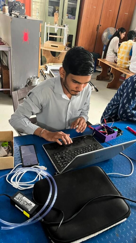
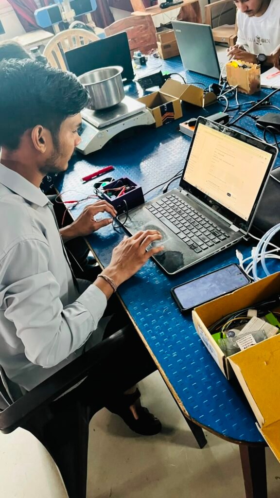
After testing the individual components, I combined all the functions into one firmware program.
The final firmware performs the following functions:
- Initializes the DHT22 sensor.
- Initializes the OLED display.
- Reads temperature and humidity.
- Displays the sensor values on the OLED.
- Checks the humidity value.
- Compares humidity with the 81% threshold.
- Activates the relay when humidity is above 81%.
- Turns ON the DC fan through the relay.
- Turns ON the red LED.
- Turns OFF the relay, fan, and LED when the humidity returns to the normal range.
The firmware was tested repeatedly during development to ensure that the complete system worked correctly.
Step 7 – Relay and Fan Testing
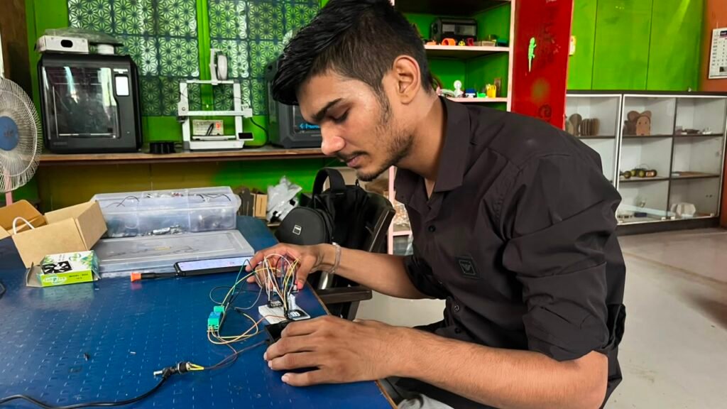
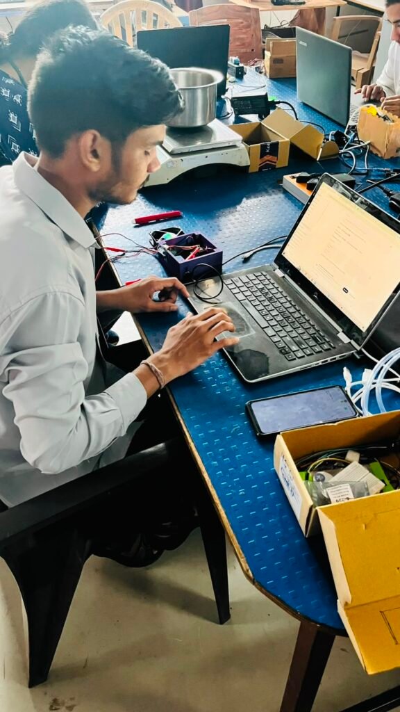
After completing the firmware, I tested the relay control separately.
The ESP32-C3 was programmed to activate the relay according to the humidity condition.
The DC fan was connected to the relay output.
When the humidity crossed the 81% threshold, the relay switched ON and the fan started running.
The red LED also turned ON to indicate the high-humidity condition.
When the humidity returned below the threshold, the relay switched OFF and the fan stopped.
This confirmed that the automatic ventilation system was working correctly.
Step 8 – PCB Design
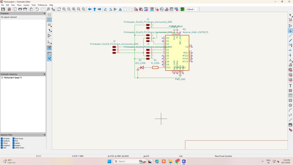
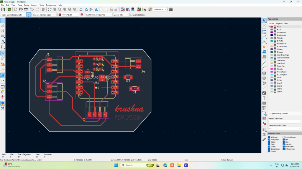
After successfully testing the complete circuit on the breadboard, I started designing the final PCB using KiCad.
I created the circuit schematic based on the tested connections.
The PCB was designed for the required connections of:
- XIAO ESP32-C3
- DHT22
- OLED display
- Relay
- DC fan
- Red LED
- Power supply
The components and connections were arranged to make the PCB compact and organized.
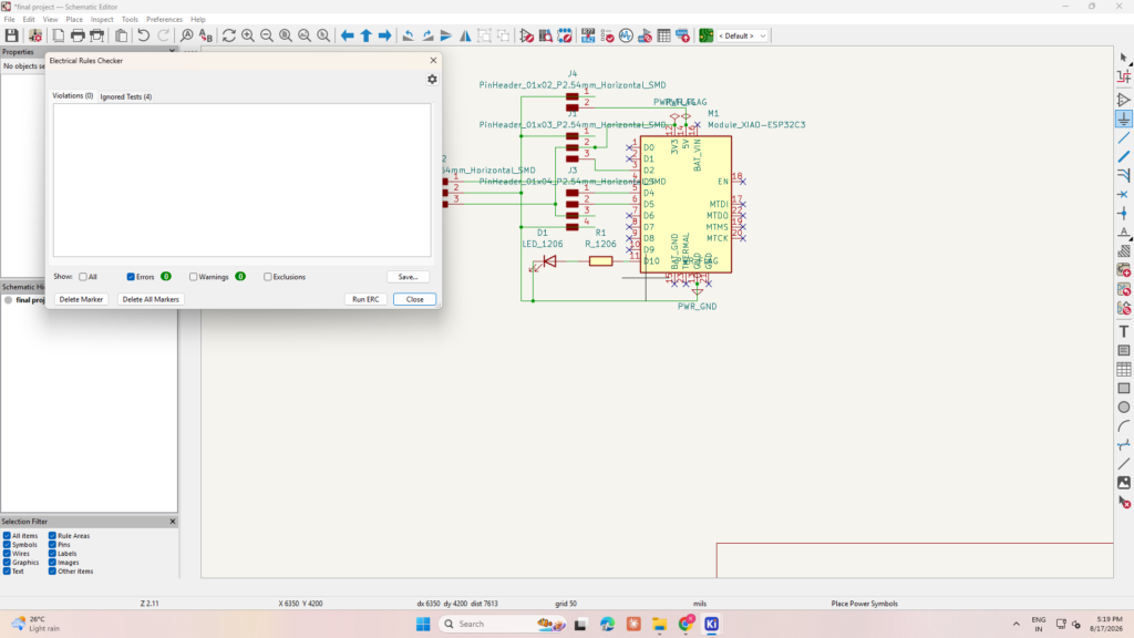
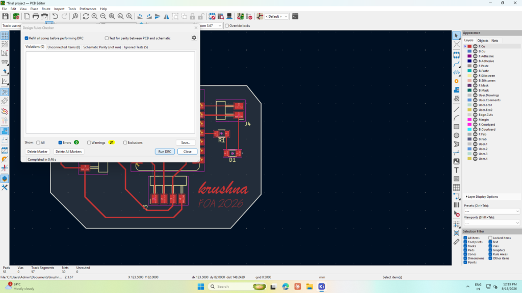
Before fabrication, I checked the schematic and PCB design for possible errors.
I used ERC (Electrical Rules Check) to check the schematic and DRC (Design Rules Check) to check the PCB layout.
After completing these checks, the PCB was prepared for fabrication.
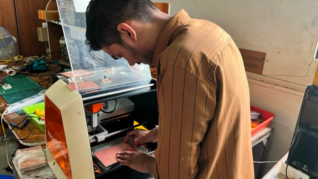
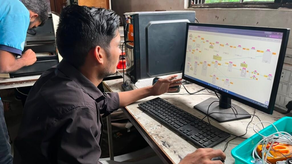
Step 9 – PCB Milling
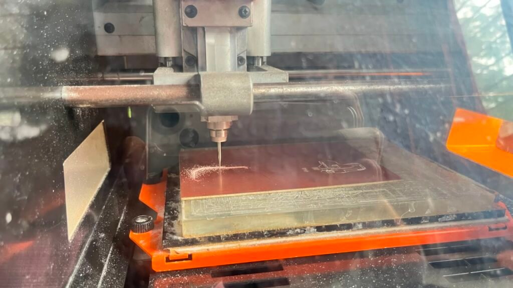
After completing the PCB design in KiCad, I fabricated the PCB using a PCB milling machine.
The milling machine removed the unwanted copper from the PCB and created the required tracks.
After milling, I cleaned the PCB and visually inspected the tracks.
I checked the board carefully before moving to the soldering stage.
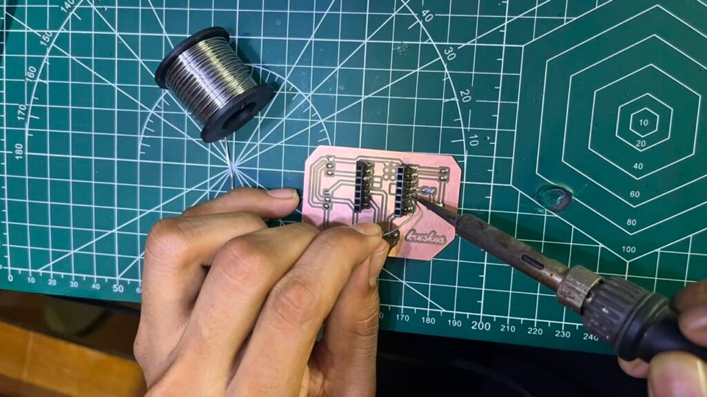
Step 10 – Connector Soldering
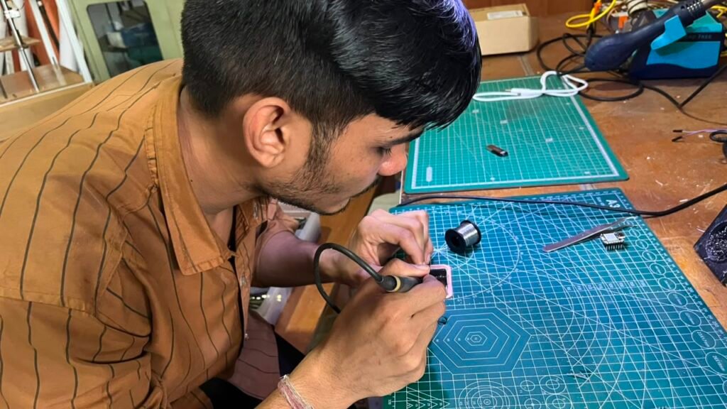
After completing the PCB milling, I soldered the required connectors onto the PCB.
The connectors were used for connecting the different components of the system, including:
- XIAO ESP32-C3
- DHT22
- OLED display
- Relay
- DC fan
- LED
- Power supply
After soldering, I checked the solder joints and made sure that there were no loose joints or unwanted connections.
Step 11 – PCB Testing
After soldering the connectors, I tested the PCB using a multimeter.
I checked the continuity of the important tracks and verified the power and signal connections.
I also checked for possible short circuits before connecting the main components.
This step helped ensure that the PCB was ready for complete system testing.
Step 12 – Connecting Components to the PCB
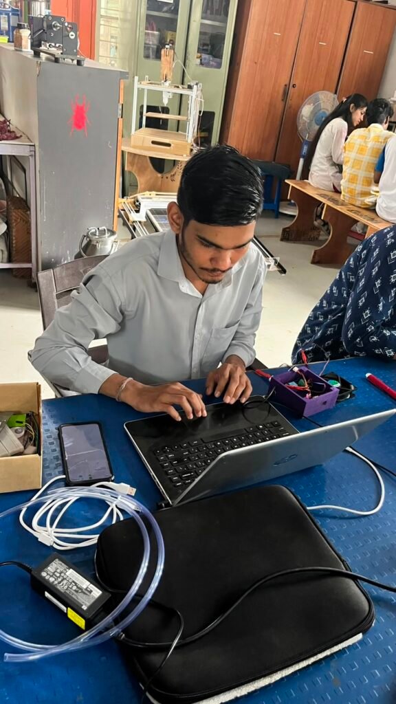
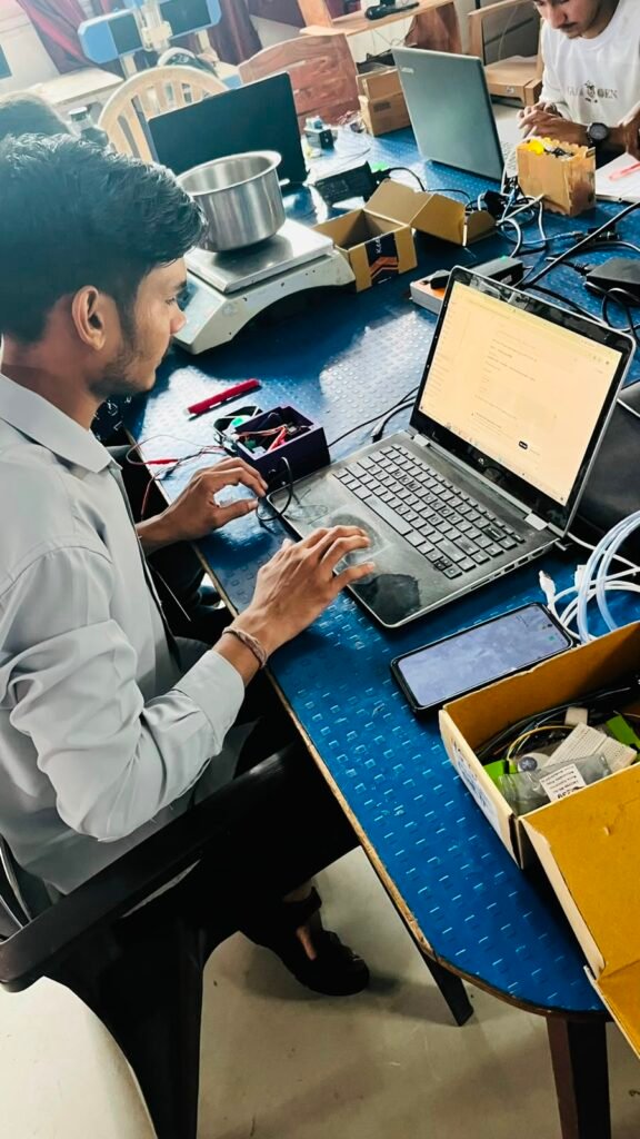
After testing the PCB, I connected all the required components.
The XIAO ESP32-C3 was connected to the PCB along with the:
- DHT22 sensor
- OLED display
- Relay
- DC fan
- Red LED
After completing all the connections, I powered the system and tested the components.
The OLED displayed the temperature and humidity readings, while the relay, fan, and LED responded according to the humidity level.
Step 13 – 3D Enclosure Design
After completing the PCB and testing the electronics, I designed an enclosure for the Smart Grain Storage Monitoring System.
The enclosure was designed according to the dimensions of the PCB and the connected components.
Openings were provided for the OLED display, LED, sensor, fan connections, power connections, and other required parts.
The purpose of the enclosure was to protect the electronics and provide a compact final structure.
Step 14 – 3D Printing
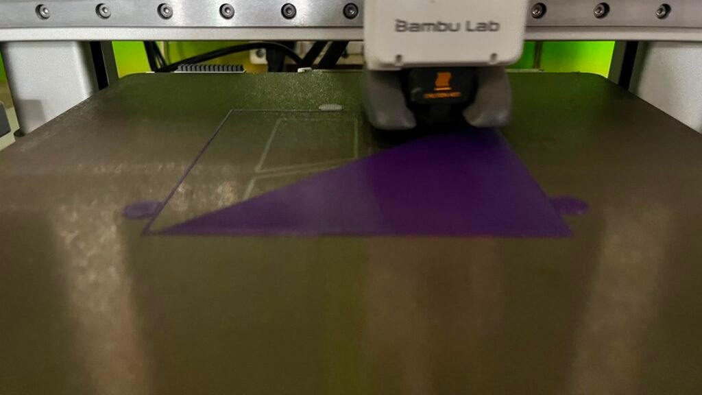
After completing the enclosure design, I exported the 3D model and prepared it for printing.
The enclosure was printed using a 3D printer with suitable filament.
After printing, I checked whether the PCB and components fitted correctly inside the enclosure.
The enclosure was then prepared for final assembly.
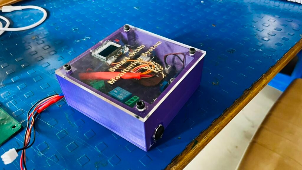
Step 15 – Final Assembly
After the enclosure was ready, I started assembling the complete Smart Grain Storage Monitoring System.
I fitted the PCB inside the enclosure and positioned the OLED display and red LED so they could be easily viewed.
The DHT22 sensor was positioned to measure the surrounding temperature and humidity.
The relay, fan connections, and power connections were arranged properly inside the enclosure.
After fitting all the components, I closed the enclosure and prepared the device for final testing.
Step 16 – Final Testing
After completing the final assembly, I performed the final testing of the Smart Grain Storage Monitoring System.
I checked:
- DHT22 temperature reading
- DHT22 humidity reading
- OLED display
- 81% humidity threshold
- Relay operation
- DC fan operation
- Red LED indication
- PCB connections
- Complete system operation
I tested the system under different humidity conditions.
When the humidity increased above 81%, the relay activated and the DC fan and red LED turned ON.
When the humidity returned below the threshold, the relay and fan turned OFF.
The final testing confirmed that the system was working according to the planned operation.
#define BLYNK_TEMPLATE_ID "TMPL3WiViB8kK"
#define BLYNK_TEMPLATE_NAME "Grain monitoring system"
#define BLYNK_AUTH_TOKEN "T5ZPO3D6oA1tlwq_5V2NzXhsGwVksKkR"

#include <WiFi.h>
#include <BlynkSimpleEsp32.h>
#include <Wire.h>
#include <Adafruit_GFX.h>
#include <Adafruit_SSD1306.h>
#include <DHT.h>

char ssid[] = "Workshop";
char pass[] = "@@vigyan@@";

// ---------- PINS ----------
#define DHT_PIN D2
#define DHT_TYPE DHT22

#define RELAY_PIN D3
#define LED_PIN D10

#define OLED_SCL D5
#define OLED_SDA D4

DHT dht(DHT_PIN, DHT_TYPE);

#define SCREEN_WIDTH 128
#define SCREEN_HEIGHT 64

Adafruit_SSD1306 display(
  SCREEN_WIDTH,
  SCREEN_HEIGHT,
  &Wire,
  -1
);

BlynkTimer timer;

bool fanState = false;


// ---------- SENSOR FUNCTION ----------

void sendSensor()
{
  float temperature = dht.readTemperature();
  float humidity = dht.readHumidity();

  if (isnan(temperature) || isnan(humidity))
  {
    Serial.println("DHT22 ERROR");

    digitalWrite(RELAY_PIN, LOW);
    fanState = false;

    Blynk.virtualWrite(V2, 0);

    display.clearDisplay();

    display.setTextColor(SSD1306_WHITE);
    display.setTextSize(2);
    display.setCursor(10, 10);
    display.println("DHT22");

    display.setTextSize(1);
    display.setCursor(15, 40);
    display.println("SENSOR ERROR");

    display.display();

    return;
  }

  Serial.print("Temperature: ");
  Serial.print(temperature);
  Serial.println(" C");

  Serial.print("Humidity: ");
  Serial.print(humidity);
  Serial.println(" %");


  // ---------- BLYNK ----------

  Blynk.virtualWrite(V0, temperature);
  Blynk.virtualWrite(V1, humidity);


  // ---------- FAN CONTROL ----------

  if (humidity > 80.0)
  {
    digitalWrite(RELAY_PIN, HIGH);

    if (!fanState)
    {
      fanState = true;

      Blynk.virtualWrite(V2, 1);

      Serial.println("FAN ON");

      Blynk.logEvent(
        "fan_on",
        "GRAIN MONITORING SYSTEM: Fan ON - Humidity above 80%"
      );
    }
  }
  else
  {
    digitalWrite(RELAY_PIN, LOW);

    if (fanState)
    {
      fanState = false;

      Blynk.virtualWrite(V2, 0);

      Serial.println("FAN OFF");
    }
  }


  // ---------- LED ----------

  digitalWrite(LED_PIN, HIGH);


  // ---------- OLED ----------

  display.clearDisplay();

  display.setTextColor(SSD1306_WHITE);

  display.setTextSize(1);
  display.setCursor(15, 0);
  display.println("GRAIN MONITORING");

  display.setTextSize(2);

  display.setCursor(0, 17);
  display.print("T:");
  display.print(temperature, 1);
  display.println("C");

  display.setCursor(0, 40);
  display.print("H:");
  display.print(humidity, 1);
  display.println("%");

  display.setTextSize(1);
  display.setCursor(83, 55);

  if (fanState)
    display.println("FAN ON");
  else
    display.println("FAN OFF");

  display.display();
}


// ---------- REFRESH BUTTON ----------

BLYNK_WRITE(V3)
{
  if (param.asInt() == 1)
  {
    Serial.println("REFRESH PRESSED");
    sendSensor();
  }
}


// ---------- SETUP ----------

void setup()
{
  Serial.begin(115200);

  // LED
  pinMode(LED_PIN, OUTPUT);
  digitalWrite(LED_PIN, HIGH);

  // Relay
  pinMode(RELAY_PIN, OUTPUT);
  digitalWrite(RELAY_PIN, LOW);

  // DHT
  dht.begin();

  // OLED
  Wire.begin(OLED_SDA, OLED_SCL);

  if (!display.begin(SSD1306_SWITCHCAPVCC, 0x3C))
  {
    Serial.println("OLED NOT FOUND");

    while (1);
  }


  // ---------- START SCREEN ----------

  display.clearDisplay();

  display.setTextColor(SSD1306_WHITE);

  display.setTextSize(2);

  display.setCursor(5, 10);
  display.println("GRAIN");

  display.setCursor(5, 32);
  display.println("MONITORING");

  display.setTextSize(1);

  display.setCursor(40, 52);
  display.println("SYSTEM");

  display.display();

  delay(3000);


  // ---------- BLYNK ----------

  Serial.println("Connecting to Blynk...");

  Blynk.begin(
    BLYNK_AUTH_TOKEN,
    ssid,
    pass
  );

  // Sensor update every 2 seconds
  timer.setInterval(2000L, sendSensor);
}


// ---------- LOOP ----------

void loop()
{
  Blynk.run();
  timer.run();
}
Final Working
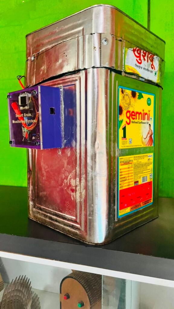
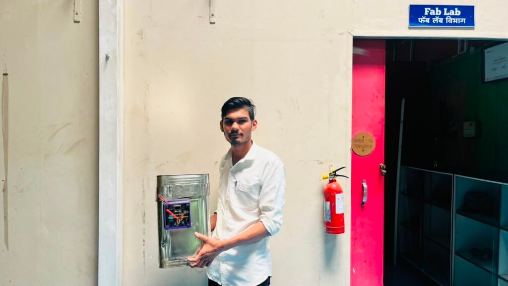
After completing the final testing, the Smart Grain Storage Monitoring System was ready as a complete working device.
The DHT22 continuously measures the temperature and humidity inside the grain storage environment.
The XIAO ESP32-C3 receives the sensor readings and displays them on the OLED.
When the humidity is 81% or below, the relay remains OFF.
When the humidity rises above 81%, the ESP32-C3 activates the relay. The relay turns ON the DC fan and the red LED.
The fan provides ventilation to help manage the high-humidity condition, while the red LED provides a visual warning.
The complete working process is:
DHT22 → XIAO ESP32-C3 → OLED Display
Humidity > 81% → ESP32-C3 → Relay → Fan ON + Red LED ON
Humidity ≤ 81% → Relay OFF → Fan OFF + Red LED OFF
Testing & Results
The final Smart Grain Storage Monitoring System was tested after completing the PCB assembly and final enclosure assembly.
The main tests included:
- Temperature measurement
- Humidity measurement
- OLED display
- 81% humidity threshold
- Relay ON/OFF operation
- DC fan ON/OFF operation
- Red LED indication
- PCB operation
- Complete system operation
The tests showed that the system was able to monitor the grain storage environment and automatically activate the ventilation system when the humidity exceeded the selected threshold.
Bill of Materials & Project Cost
The approximate cost of the project depends on the components and fabrication materials used.
Note: The exact project cost depends on the actual purchase price of the components, PCB fabrication, wiring, power supply, and 3D-printing material.
| Sr. No. | Component / Material | Qty. | Approx. Price (₹) |
|---|---|---|---|
| 1 | XIAO ESP32-C3 | 1 | ₹650 |
| 2 | DHT22 Temperature & Humidity Sensor | 1 | ₹180 |
| 3 | 0.96″ OLED Display | 1 | ₹140 |
| 4 | Relay Module | 1 | ₹50 |
| 5 | DC Fan | 1 | ₹150 |
| 6 | DC-DC Converter (12V to 5V) | 1 | ₹80 |
| 7 | Red LED | 1 | ₹5 |
| 8 | Resistor | 1 | ₹2 |
| 9 | Connectors | As required | ₹30 |
| 10 | Wires | As required | ₹30 |
| 11 | PCB Material | 1 | ₹150 |
| 12 | 3D Printing Material | As required | ₹100 |
| Total Approximate Cost | ₹1,567 |
Challenges and Solutions
During the development of the Smart Grain Storage Monitoring System, I faced several challenges during hardware testing and programming.
DHT22 Sensor Reading
The DHT22 sensor required correct wiring and library configuration to obtain stable readings.
Solution:
I checked the sensor connections and firmware until the temperature and humidity readings were displayed correctly.
OLED Display
The OLED required correct I2C connections and address configuration.
Solution:
I checked the SDA and SCL connections and configured the OLED correctly.
Humidity Threshold
The relay needed to activate only when the humidity crossed the selected limit.
Solution:
I programmed the ESP32-C3 with an 81% humidity threshold and tested the relay operation under different conditions.
Relay and Fan Control
The DC fan had to automatically turn ON when humidity became high.
Solution:
I connected the fan through the relay and tested the complete automatic control system.
PCB Development
The PCB had to be checked before fabrication.
Solution:
I used ERC, DRC, visual inspection, and a multimeter to verify the PCB connections.
Enclosure Design
The enclosure needed to accommodate the PCB and all the components correctly.
Solution:
I designed the enclosure according to the actual dimensions and arrangement of the components.
Conclusion
The Smart Grain Storage Monitoring System was successfully developed from an initial idea into a working automatic environmental monitoring and ventilation system.
The project was developed step by step, starting with research and component selection, followed by breadboard testing, DHT22 and OLED integration, firmware development, relay and fan testing, PCB design, PCB milling, component assembly, 3D enclosure design, and final testing.
The final system can continuously monitor the temperature and humidity inside the grain storage area.
When the humidity rises above 81%, the system automatically activates the relay, which turns ON the DC fan and red LED.
This project demonstrates how an embedded system can be used to create an automatic monitoring and control solution for grain storage.
Through this project, I gained practical experience in embedded programming, sensor interfacing, IoT, relay control, PCB design, PCB fabrication, electronics testing, and 3D enclosure design.