Title:- Gas Leakage Detector
Student Name: Pranay Mudhagoni
Problem Statement
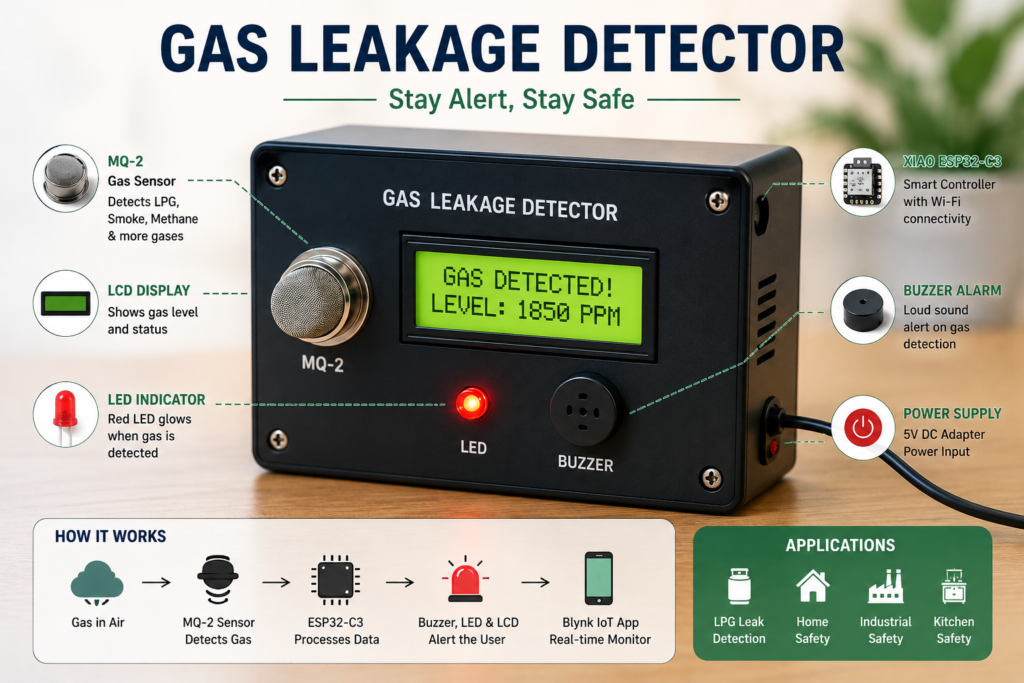
Gas leakage can create serious safety risks, and conventional gas detectors may provide only local alerts without remote monitoring. To address this issue, the project focuses on developing a smart gas detection system using a XIAO ESP32-C3 and MQ-2 gas sensor. When gas is detected above a predefined threshold, the system activates a buzzer and LED, displays the gas status on the LCD, and sends a gas detected notification to the Blynk mobile application. This enables users to receive immediate alerts and monitor the gas detection status remotely, improving safety and response time.
Proposed solution
The proposed solution is to develop a smart gas detection and alert system using a XIAO ESP32-C3 and MQ-2 gas sensor. The MQ-2 continuously monitors the surrounding environment for gas leakage and sends the detected gas level to the ESP32-C3. When the gas level exceeds the predefined threshold, the system activates a buzzer and LED, displays “Gas Detected” on the LCD, and sends an instant notification through the Blynk mobile application. When the gas level is within the safe range, the system displays “Normal” and keeps the alarm indicators off. This provides real-time local and remote monitoring, enabling users to respond quickly to potential gas leakage and improve overall safety.
Working principle
The MQ2 gas sensor detects the presence of LPG, smoke, methane, and other combustible gases by measuring the change in resistance of its sensing element when exposed to these gases. This change is output as an analog voltage, which is read by the XIAO ESP32-C3 microcontroller.
The microcontroller continuously samples this analog value and compares it against a predefined threshold:
- Below threshold → Air quality is safe. The LCD displays the current gas level, and the system stays in standby (LED off, buzzer silent).
- At or above threshold → A gas leak is detected. The XIAO ESP32-C3 immediately turns on the LED as a visual warning, activates the buzzer as an audible alarm, and updates the LCD to show a “Gas Detected” and warning notification send through Blynk app message alongside the reading.
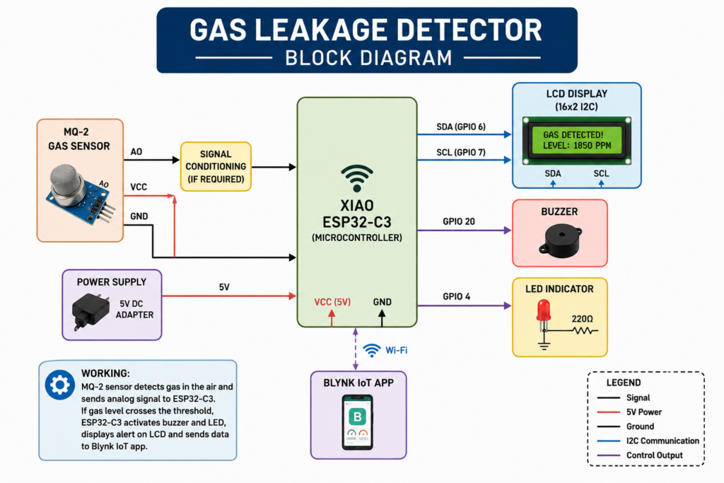
Block Diagram:
System design:
- MQ2 Sensor → Analog Output (AO) pin connected to an ADC-capable GPIO on the XIAO ESP32-C3; VCC and GND connected to the board’s 5V and GND .
- LCD Display → Connected via I2C (SDA/SCL) to the corresponding I2C pins on the XIAO ESP32-C3, reducing the number of wires needed and simplifying the display of real-time gas readings and alert messages.
- LED → Connected through a current-limiting resistor to a digital GPIO pin, used as the visual gas-leak indicator.
- Buzzer → Connected to another digital GPIO pin, driven HIGH/LOW by the microcontroller to sound the alarm when a leak is detected.
- All grounds (sensor, LCD, LED, buzzer) are tied to a common ground with the XIAO ESP32-C3 to ensure stable readings and reliable switching.
Project Development Step by Step
After deciding the idea and basic requirements of the Gas Leakage Detector, I started developing the project step by step. I first tested the electronics on a breadboard and worked on the code before moving towards the final PCB.
The complete development process was done in the following stages:
Research → Components Ordering → Breadboard Testing → Coding → Debugging → Blynk Integration → PCB Design → PCB Milling → PCB Testing → Assembly → Final Testing
Research
I started the project by researching how a gas leakage detection system could be made. I looked at different microcontrollers, gas sensors, displays, and IoT options that could be used for the project.
After comparing the requirements, I decided to use the XIAO ESP32-C3 because it has built-in Wi-Fi and is small enough to fit inside a compact enclosure. I also planned the basic features such as real-time gas level monitoring on an LCD display, LED and buzzer alerts, and Blynk app notifications for remote alerting.
Components Ordering
Once the research was complete, I finalized the components needed for the project and placed the orders accordingly. Each component was chosen based on the planned circuit and the functionality required for the Gas Leakage Detector.
The main components included the XIAO ESP32-C3, MQ2 gas sensor, LCD display, LED, buzzer, and other necessary wiring and connectors.
Breadboard Testing
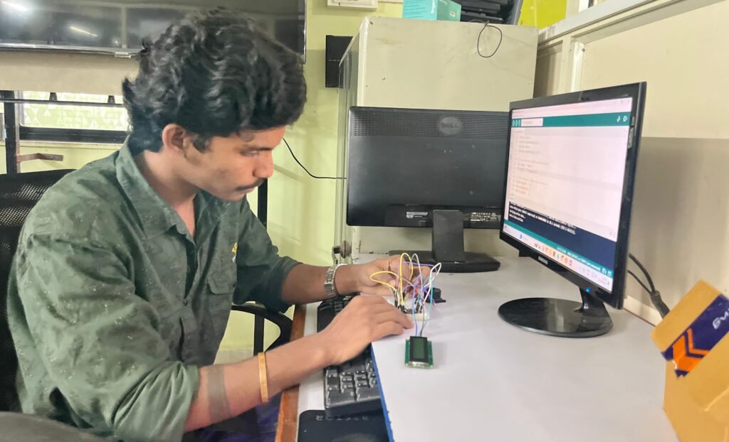
After receiving all the components, I began testing the project on a breadboard. I connected the XIAO ESP32-C3 with the MQ2 gas sensor, LCD display, LED, and buzzer according to the planned wiring.
I tested each component individually first and then combined them into a single circuit. This step helped me verify that every part was functioning correctly before moving ahead to the PCB stage.
| Component | XIAO ESP32-C3 Pin |
|---|---|
| MQ2 Sensor (Analog Out) | A0 |
| LCD SDA | D4 |
| LCD SCL | D5 |
| LED | D8 |
| Buzzer | D9 |
Final Code and Firmware
After testing the individual components, I developed and refined the firmware according to the required functionality of the project. This included implementing gas concentration sensing via the MQ2 sensor, LCD display updates, LED and buzzer alert triggers, and threshold-based leak detection logic.
Following further modifications and testing, I uploaded the finalized firmware to the XIAO ESP32-C3. This version served as the foundation for Blynk integration and complete system testing.
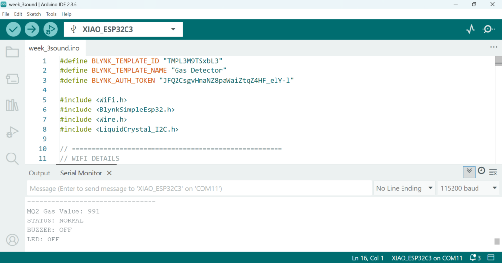
This is the final complete code used for the Gas Leakage Detector.
#define BLYNK_TEMPLATE_ID "TMPL3M9TSxbL3"
#define BLYNK_TEMPLATE_NAME "Gas Detector"
#define BLYNK_AUTH_TOKEN "JFQ2CsgvHmaNZ8paWaiZtqZ4HF_elY-l"

#include <WiFi.h>
#include <BlynkSimpleEsp32.h>
#include <Wire.h>
#include <LiquidCrystal_I2C.h>

// =====================================================
// WIFI DETAILS
// =====================================================

char ssid[] = "OnePlus";
char pass[] = "asdfghjkl";

// =====================================================
// PIN DEFINITIONS
// =====================================================

#define MQ2_PIN     2
#define BUZZER_PIN  20
#define LED_PIN     4

#define SDA_PIN     6
#define SCL_PIN     7

// =====================================================
// LCD
// =====================================================

LiquidCrystal_I2C lcd(0x27, 16, 2);

// =====================================================
// GAS THRESHOLD
// =====================================================

#define GAS_THRESHOLD 1800

// =====================================================
// BLYNK TIMER
// =====================================================

BlynkTimer timer;

// =====================================================
// GAS SENSOR FUNCTION
// =====================================================

void readGasSensor()
{
  int gasValue = analogRead(MQ2_PIN);

  Serial.println("--------------------------------");

  Serial.print("MQ2 Gas Value: ");
  Serial.println(gasValue);

  // ===================================================
  // GAS DETECTED
  // ===================================================

  if (gasValue >= GAS_THRESHOLD)
  {
    // Turn ON buzzer and LED
    digitalWrite(BUZZER_PIN, HIGH);
    digitalWrite(LED_PIN, HIGH);

    // ---------------- LCD ----------------

    lcd.clear();

    lcd.setCursor(0, 0);
    lcd.print("!!! GAS !!!");

    lcd.setCursor(0, 1);
    lcd.print("Detected:");
    lcd.print(gasValue);

    // ---------------- SERIAL ----------------

    Serial.println("STATUS: GAS DETECTED");
    Serial.println("BUZZER: ON");
    Serial.println("LED: ON");

    // =================================================
    // BLYNK DATASTREAMS
    // =================================================

    // V0 = Gas Value
    Blynk.virtualWrite(V0, gasValue);

    // V1 = Gas Status
    Blynk.virtualWrite(V1, "GAS DETECTED");

    // V2 = Alarm Indicator
    // Screenshot shows maximum = 225
    Blynk.virtualWrite(V2, 225);

    // V3 = LED Status
    Blynk.virtualWrite(V3, "ON");

    // V4 = Buzzer Status
    Blynk.virtualWrite(V4, "ON");
  }

  // ===================================================
  // NORMAL
  // ===================================================

  else
  {
    // Turn OFF buzzer and LED
    digitalWrite(BUZZER_PIN, LOW);
    digitalWrite(LED_PIN, LOW);

    // ---------------- LCD ----------------

    lcd.clear();

    lcd.setCursor(0, 0);
    lcd.print("STATUS: NORMAL");

    lcd.setCursor(0, 1);
    lcd.print("Gas:");
    lcd.print(gasValue);

    // ---------------- SERIAL ----------------

    Serial.println("STATUS: NORMAL");
    Serial.println("BUZZER: OFF");
    Serial.println("LED: OFF");

    // =================================================
    // BLYNK DATASTREAMS
    // =================================================

    // V0 = Gas Value
    Blynk.virtualWrite(V0, gasValue);

    // V1 = Gas Status
    Blynk.virtualWrite(V1, "NORMAL");

    // V2 = Alarm Indicator
    Blynk.virtualWrite(V2, 0);

    // V3 = LED Status
    Blynk.virtualWrite(V3, "OFF");

    // V4 = Buzzer Status
    Blynk.virtualWrite(V4, "OFF");
  }
}

// =====================================================
// SETUP
// =====================================================

void setup()
{
  Serial.begin(115200);

  // ===================================================
  // GPIO SETUP
  // ===================================================

  pinMode(MQ2_PIN, INPUT);
  pinMode(BUZZER_PIN, OUTPUT);
  pinMode(LED_PIN, OUTPUT);

  // Initially OFF
  digitalWrite(BUZZER_PIN, LOW);
  digitalWrite(LED_PIN, LOW);

  // ===================================================
  // LCD SETUP
  // ===================================================

  Wire.begin(SDA_PIN, SCL_PIN);

  lcd.init();
  lcd.backlight();

  lcd.clear();

  lcd.setCursor(0, 0);
  lcd.print("GAS DETECTOR");

  lcd.setCursor(0, 1);
  lcd.print("Starting...");

  delay(2000);

  // ===================================================
  // BLYNK CONNECTION
  // ===================================================

  lcd.clear();

  lcd.setCursor(0, 0);
  lcd.print("Connecting WiFi");

  Blynk.begin(BLYNK_AUTH_TOKEN, ssid, pass);

  // ===================================================
  // READY
  // ===================================================

  lcd.clear();

  lcd.setCursor(0, 0);
  lcd.print("GAS DETECTOR");

  lcd.setCursor(0, 1);
  lcd.print("Ready");

  delay(1000);

  // Read sensor every 1 second
  timer.setInterval(1000L, readGasSensor);
}

// =====================================================
// LOOP
// =====================================================

void loop()
{
  Blynk.run();
  timer.run();
}
Blynk IoT Integration
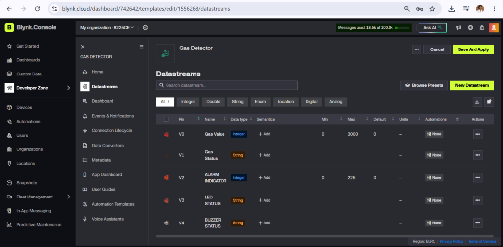
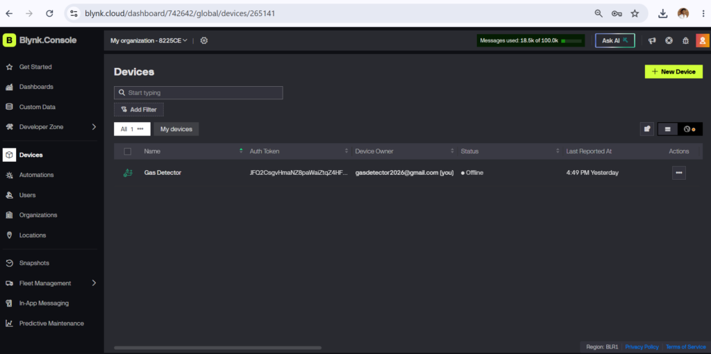
Once the hardware and final code were functioning properly, I moved on to integrating the project with the Blynk IoT platform. I created a Blynk template and device, then configured the necessary datastreams and virtual pins for monitoring the Gas Leakage Detector remotely.
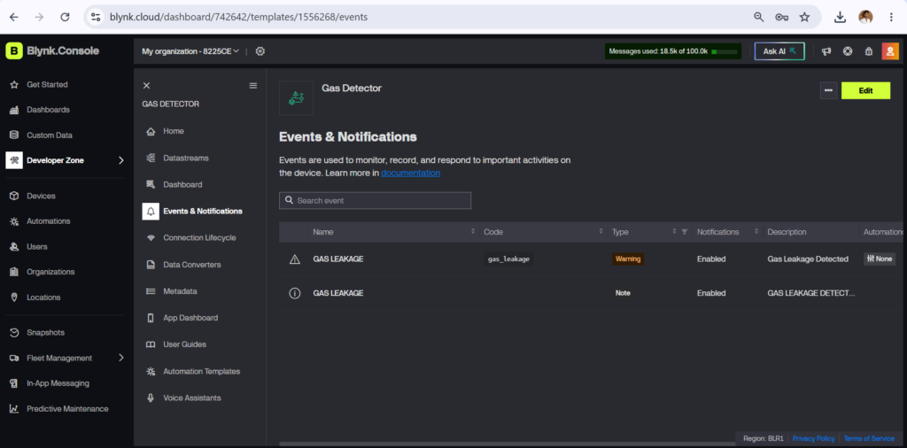
I added the required elements in the Blynk app, including real-time gas level monitoring, a notification system for gas detection alerts, and overall device status indication. After completing this setup, I connected the XIAO ESP32-C3 to Blynk and tested the notification system alongside the actual hardware to ensure alerts were triggered accurately and delivered without delay.
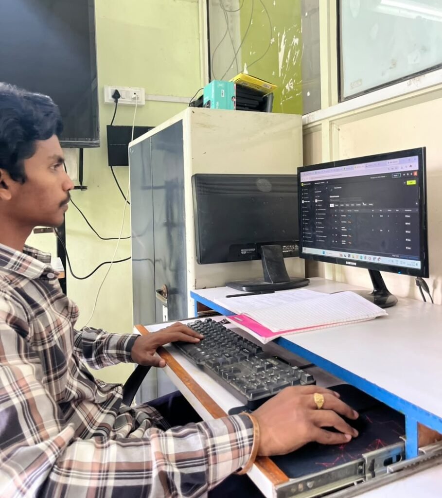
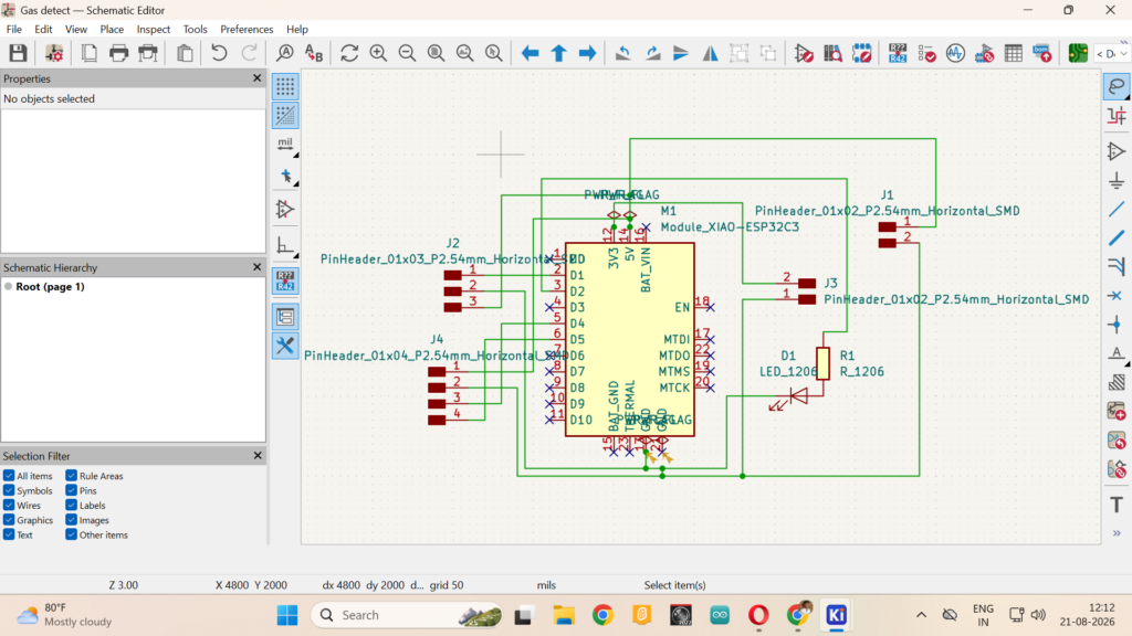
PCB Design:
In the final project PCB process, I created the KiCad schematic with XIAO ESP32-C3, MQ-2 sensor, LCD, buzzer, and LED connections for PCB fabrication.
I update it in the PCB editor.

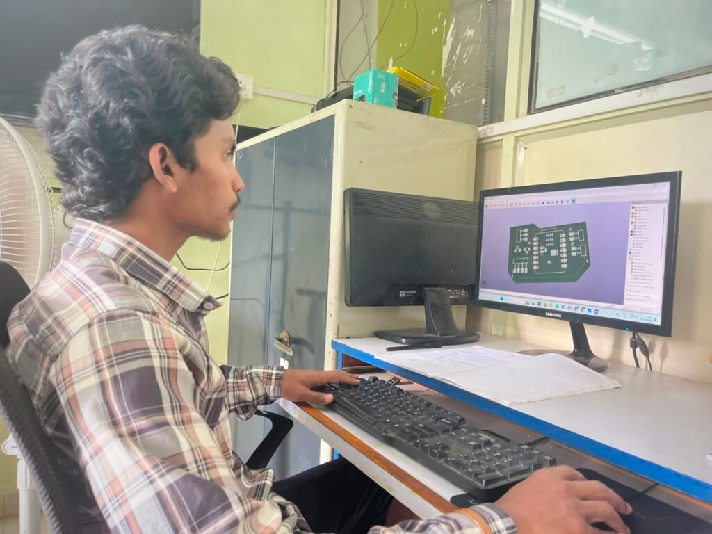
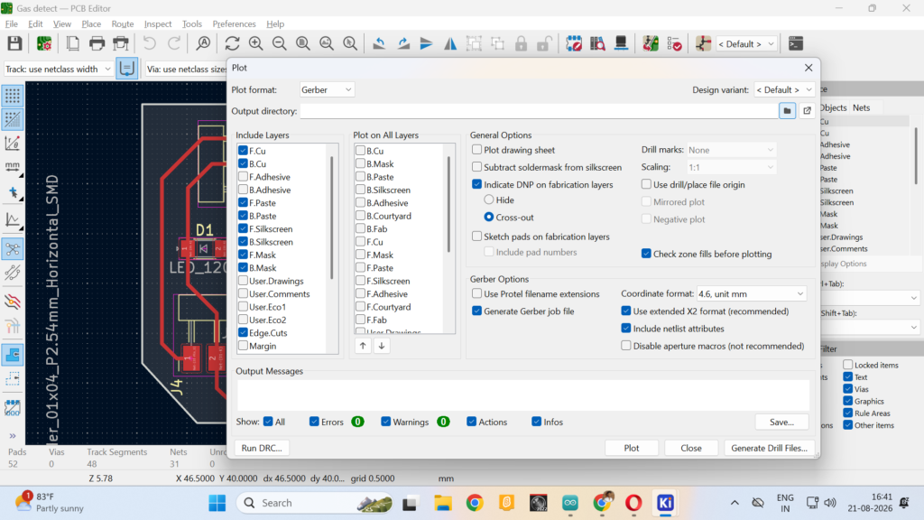
After completing the PCB routing, I generated the Gerber and PNG files for fabrication.
PCB Milling
After finalizing the PCB design and verifying it through ERC and DRC checks, I used the completed KiCad design to fabricate the PCB using a milling machine.
The milling process removed the unwanted copper from the board, forming the required traces and connection pads. Once the milling was complete, I cleaned the PCB thoroughly and inspected the traces to ensure the board was ready for the next stage of assembly.
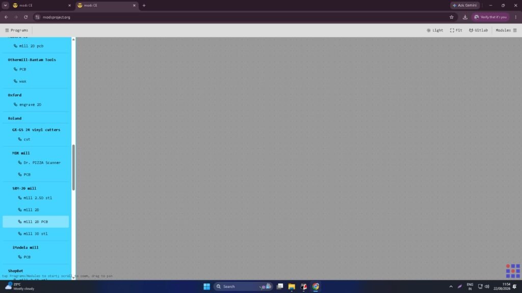
Click on Mill 2D PCB.
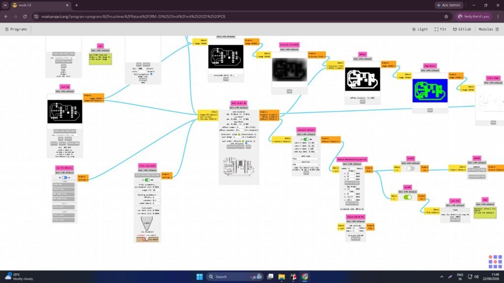
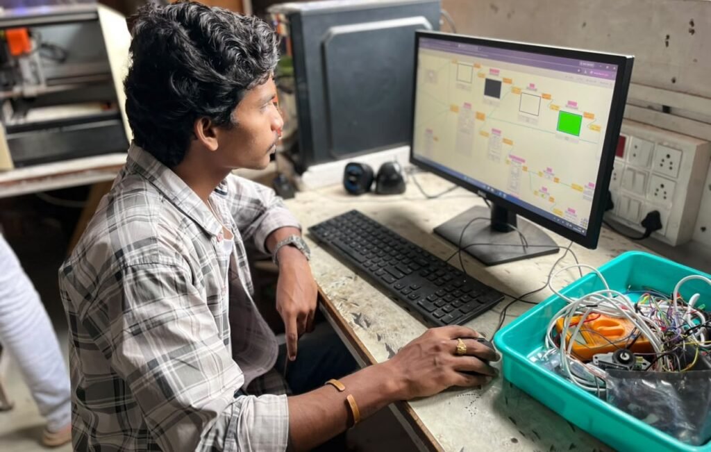
During the PCB cutting process, I used a 1/64-inch milling bit for isolation and changed it to a 1/32-inch milling bit for the edge cut.

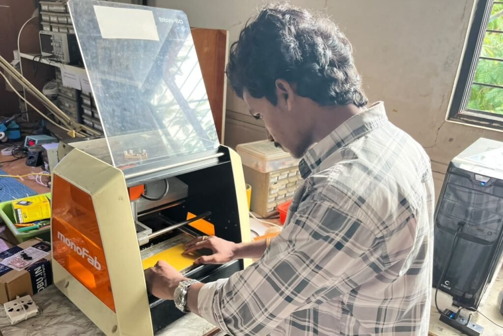
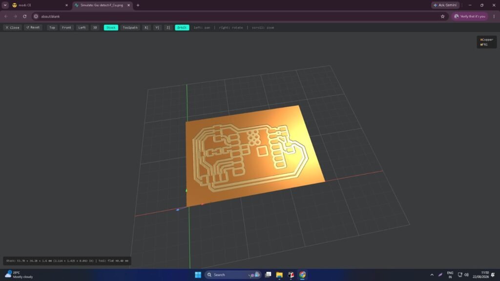
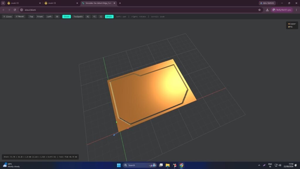
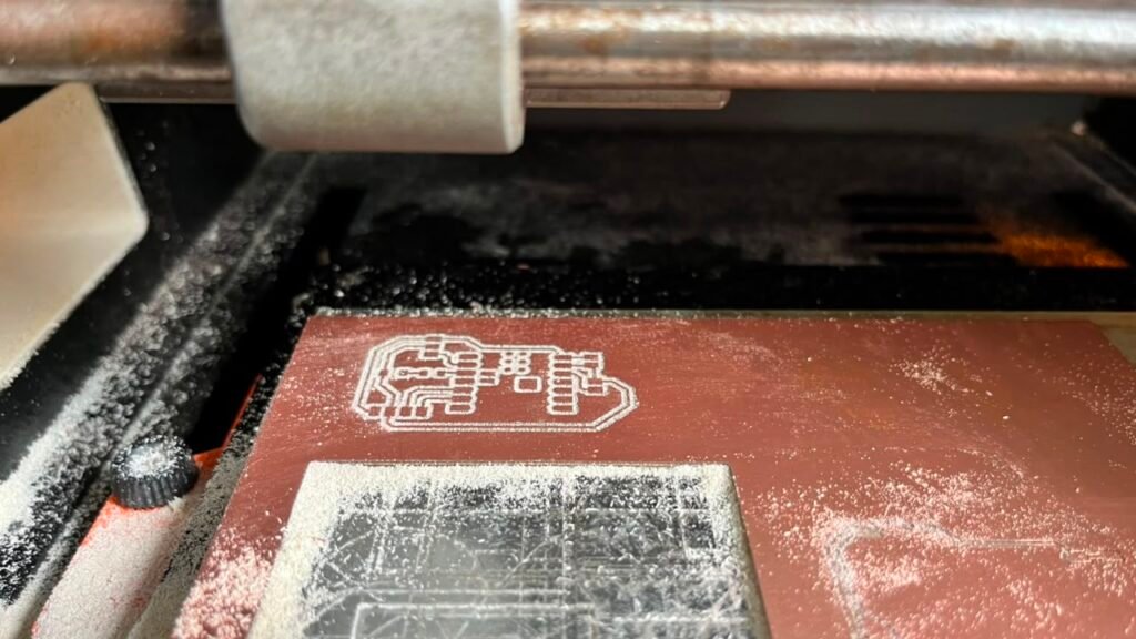
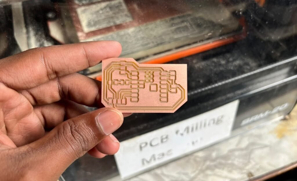
The PCB cutting was completed successfully.
Connector Soldering
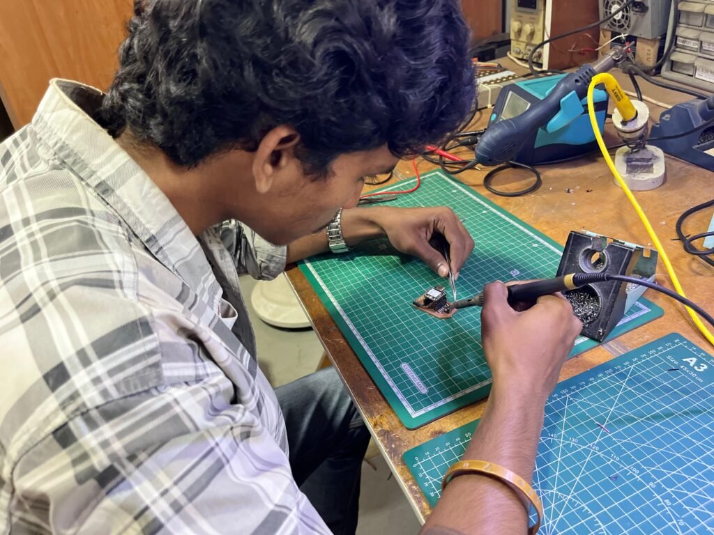
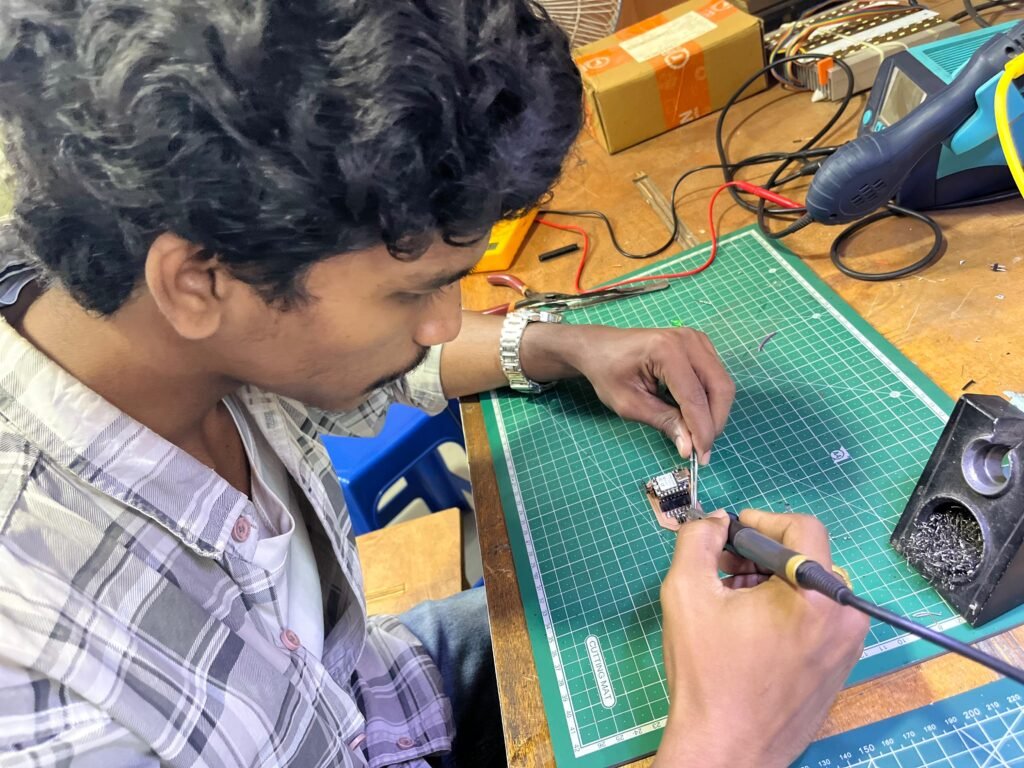
Once the PCB milling was finished, I soldered the necessary connectors and terminals onto the board. These connectors served as the interface between the PCB and the various components of the Gas Leakage Detector.
After completing the soldering, I inspected all the joints to confirm there were no short circuits or loose connections before proceeding to the testing stage.
Final Assembly
Later, I began assembling the complete Gas Leakage Detector. I fitted the PCB along with all the required components and arranged them neatly to ensure proper functioning.
The LCD display, LED, buzzer, and MQ2 sensor were positioned properly so that the device could be easily monitored and operated from the outside. Once all the components were fitted, I finalized the setup and prepared the device for final testing.

Final Testing
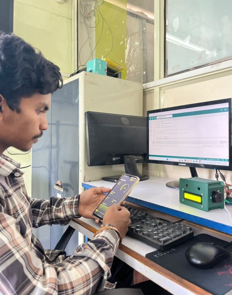
After completing the assembling, I conducted the final round of testing on the Gas Leakage Detector. I verified the sensor readings, LCD display output, LED and buzzer alerts, and Blynk app notifications to ensure each function operated as intended.
I also evaluated the complete device by exposing it to controlled gas conditions to confirm that the system responded accurately once fully assembled inside its enclosure. The final testing confirmed that the Gas Leakage Detector was able to perform all the required functions as planned.
Results
The Gas Leakage Detector was tested after completing the PCB assembly. Various functions of the device were checked to ensure that the hardware and software components were working together as expected.
The main tests included:
- Gas concentration sensing
- LCD display readings
- LED alert indication
- Buzzer alarm activation
- Threshold detection accuracy
- Blynk app notification
- Response and recovery time
The tests confirmed that the Gas Leakage Detector was able to accurately detect gas leaks, trigger the LED and buzzer alerts, display real-time readings on the LCD, and send notifications to the Blynk app whenever gas levels exceeded the safe threshold.
Bill of Materials & Project Cost
The table below outlines the approximate cost of the main components and materials used to build the Gas Leakage Detector. The costing is based on the actual purchase prices and materials used during fabrication.
| Sr. No. | Component / Material | Qty. | Unit Cost | Total Cost |
|---|---|---|---|---|
| 1 | XIAO ESP32-C3 | 1 | ₹779 | ₹779 |
| 2 | MQ2 Gas Sensor | 1 | ₹99 | ₹99 |
| 3 | 16×2 LCD Display (I2C) | 1 | ₹249 | ₹249 |
| 4 | Active Buzzer | 1 | ₹40 | ₹40 |
| 5 | LED | 1 | ₹5 | ₹5 |
| 6 | Connectors | 10 | ₹7 | ₹70 |
| Total | ₹1,242 |
Approximate material cost: ₹1,242
Challenges and Solutions
While developing the Gas Leakage Detector, I encountered several challenges during both the hardware and software testing phases. The project required multiple rounds of testing and code refinement before all the functions operated correctly together.
Some of the key challenges included:
- Code debugging: The code needed to be revised several times during testing to ensure all functions worked as intended.
- Blynk integration: Configuring the template, device, datastreams, and notification alerts required careful setup and repeated testing.
- Sensor calibration: The MQ2 sensor’s threshold values had to be tested and adjusted to accurately distinguish between normal air and gas leak conditions.
- PCB development: The PCB connections had to be verified using ERC, DRC, and a multimeter before mounting the components.
- Component alignment: The wiring and placement of the sensor, LCD, LED, and buzzer had to be arranged carefully to avoid interference and ensure reliable readings.
These challenges were overcome through repeated testing, debugging, and making adjustments wherever necessary.
Conclusion
The Gas Leakage Detector was successfully developed from an initial concept into a fully functional IoT-based safety device. The project progressed step by step, beginning with research and breadboard testing, followed by firmware development, sensor calibration, Blynk integration, PCB fabrication, and final assembly.
The completed device continuously monitors the surrounding air for combustible and toxic gases using the MQ2 sensor, displays real-time readings on the LCD, and triggers immediate LED and buzzer alerts whenever gas levels exceed the safe threshold. It also sends instant push notifications through the Blynk app, ensuring the user stays informed even when away from the location.
Through this project, I gained hands-on experience in embedded programming, sensor interfacing, IoT integration, electronics prototyping, PCB design, and PCB fabrication. Beyond the technical skills, the project reinforced the importance of iterative testing and debugging in building a dependable safety system. Overall, this Gas Leakage Detector demonstrates how affordable microcontrollers and simple sensors can be combined to create a practical, low-cost solution for early gas leak detection — one that can help prevent accidents in homes, kitchens, and small workshops, and that can be further developed into a more advanced safety product in the future.