Introduction :
The Black Soldier Fly (BSF) Environmental Monitoring and Automatic Roof Control System is an automation-based project developed to maintain suitable environmental conditions for BSF larvae cultivation. The system integrates sensors, an Arduino microcontroller, and an automatic roof mechanism to regulate sunlight exposure and protect the larvae from excessive heat. By continuously monitoring environmental conditions and controlling the roof automatically, the project minimizes manual intervention, improves habitat stability, and demonstrates the practical application of embedded systems, automation, and smart agricultural technology.
5 June, 2026 to 12 June, 2026
Project Planning and Requirement Analysis :
The first day was dedicated to understanding the project requirements and planning the overall system architecture. Research was conducted on the environmental conditions required for healthy Black Soldier Fly (BSF) larvae cultivation, with particular focus on regulating sunlight exposure to maintain a suitable habitat. Based on the project requirements, different automation techniques for environmental monitoring were studied, including sunlight sensing methods and automatic roof control mechanisms.
After comparing available light sensors, the BH1750 digital light intensity sensor was selected due to its high accuracy, digital output, and easy integration with the Arduino Uno. The overall system workflow was then designed, starting from sunlight detection to automatic roof movement.
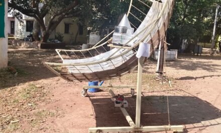
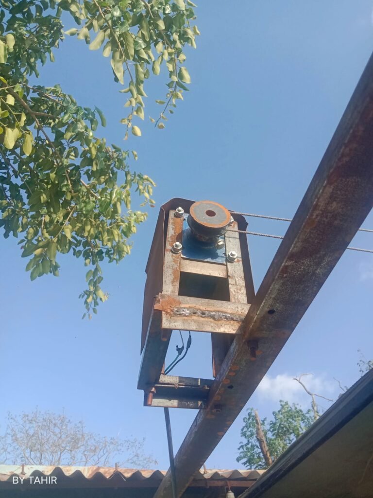
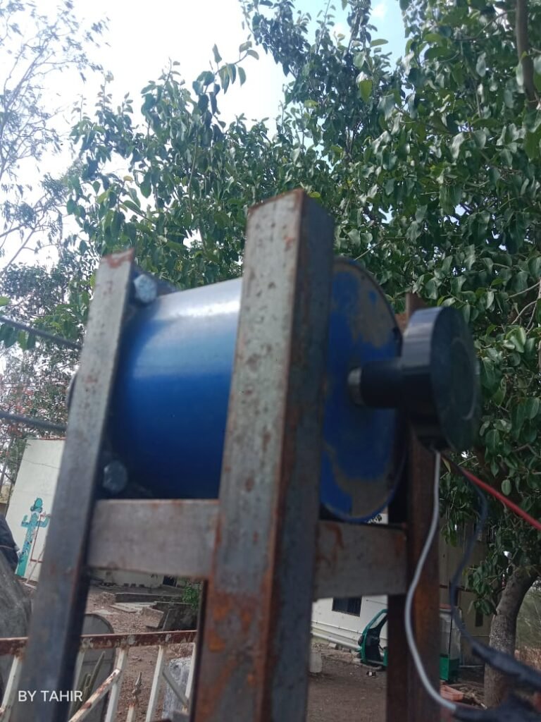
An existing roof mechanism equipped with a vibration system was inspected and tested manually to understand its mechanical operation. During testing, it was observed that although the mechanism moved smoothly when operated manually, the available motor was unable to drive the roof because its output torque was insufficient for the applied load. This mechanical limitation was identified during the initial analysis, and preliminary torque calculations were initiated to determine the specifications of a suitable motor for reliable operation. A list of the required electronic and mechanical components was also prepared, establishing the foundation for the subsequent hardware development phase.
Work Completed
- Defined the project objectives and system requirements.
- Studied the environmental requirements for BSF larvae cultivation.
- Researched sunlight sensing and automatic roof control techniques.
- Selected the Arduino Uno and BH1750 light intensity sensor.
- Examined and manually tested the existing roof mechanism.
- Identified that the available motor did not provide sufficient torque to move the roof.
- Began preliminary torque calculations for selecting an appropriate motor.
- Prepared the list of required electronic and mechanical components.
- Planned the overall hardware and software workflow.
Hardware Preparation and Individual Component Testing :
Today, I focused on preparing all the hardware components required for the Sunlight-Based Automatic Roof Control System. Before assembling the complete system, I carefully inspected every component to ensure it was in proper working condition. This step was essential because faulty hardware can lead to incorrect system behavior and make software debugging difficult.
The first task was organizing all the required components, including the Arduino UNO, relay modules, BH1750 light intensity sensor, limit switches, connecting wires, power supply, motor driver connections, and DC gear motor. After arranging the components, I verified the wiring and checked for any damaged cables or loose connections.
Next, I tested each relay module individually using a simple Arduino test program. During the test, I confirmed that each relay switched ON and OFF correctly by observing the indicator LEDs and listening for the clicking sound. This ensured that both relays were functioning properly and could later be used to control the roof opening and closing mechanism.
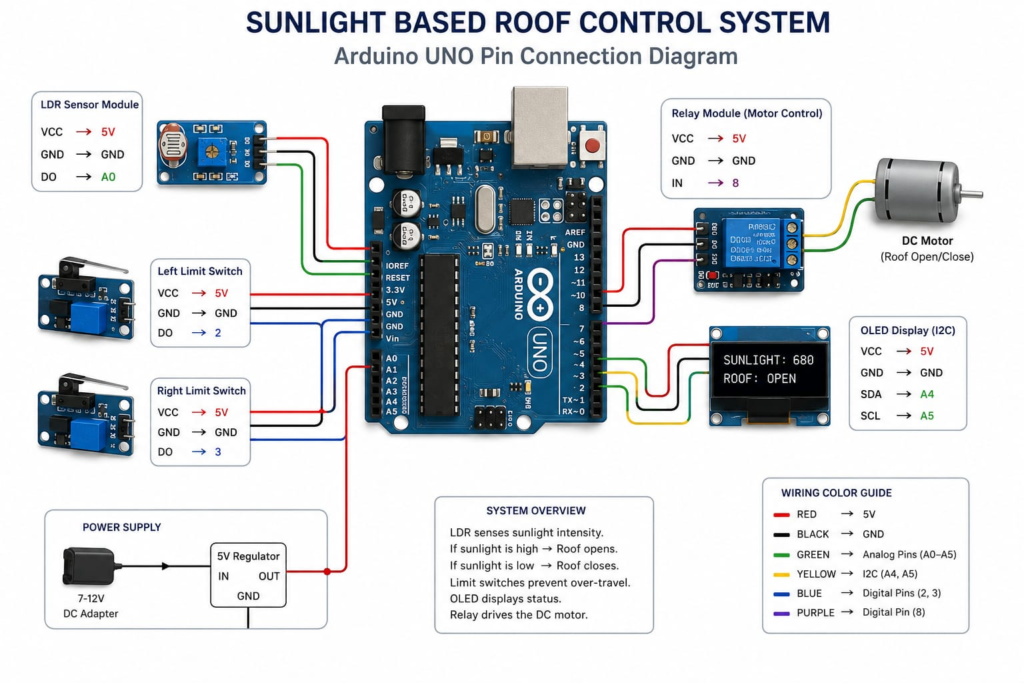
Finally, the limit switches were tested one by one using a simple digital input program. Each switch correctly changed its output state when pressed and released. This verified that they would be able to stop the roof safely at the fully open and fully closed positions.
Hardware Integration and System Verification :
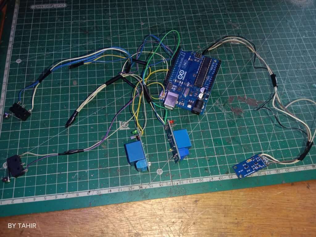
Today, I assembled the complete hardware setup of the Sunlight-Based Automatic Roof Control System according to the designed circuit diagram. All previously tested components were connected to the Arduino UNO using the required pin configuration.
The relay modules were connected to the Arduino digital output pins, while the BH1750 sunlight sensor was connected through the I2C communication pins (SDA and SCL). The limit switches were connected as digital inputs to detect the fully open and fully closed positions of the roof. After completing the wiring, every connection was rechecked to avoid loose wires, incorrect pin assignments, and short circuits.
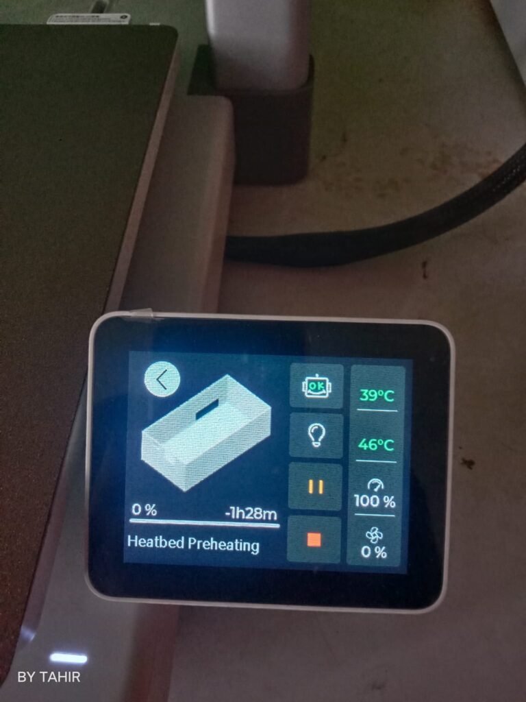
Once the hardware assembly was completed, the Arduino program was uploaded to the board. Individual hardware testing was repeated after integration to ensure that each module was still functioning correctly. The sunlight sensor continuously measured ambient light intensity, and the values were displayed on the Serial Monitor. The relay modules responded according to the programmed light threshold by activating the motor control outputs.
The limit switches were also tested during operation. When either limit switch was activated, the motor stopped immediately, preventing over-travel of the roof mechanism. Multiple test cycles were performed under different lighting conditions by exposing the sensor to sunlight and then reducing the light intensity. The complete system responded correctly by opening and closing the roof automatically.
Hardware Integration and System Verification :
Today, I assembled the complete hardware setup of the Sunlight-Based Automatic Roof Control System according to the designed circuit diagram. All previously tested components were connected to the Arduino UNO using the required pin configuration.
The relay modules were connected to the Arduino digital output pins, while the BH1750 sunlight sensor was connected through the I2C communication pins (SDA and SCL). The limit switches were connected as digital inputs to detect the fully open and fully closed positions of the roof. After completing the wiring, every connection was rechecked to avoid loose wires, incorrect pin assignments, and short circuits.
Once the hardware assembly was completed, the Arduino program was uploaded to the board. Individual hardware testing was repeated after integration to ensure that each module was still functioning correctly. The sunlight sensor continuously measured ambient light intensity, and the values were displayed on the Serial Monitor. The relay modules responded according to the programmed light threshold by activating the motor control outputs.
The limit switches were also tested during operation. When either limit switch was activated, the motor stopped immediately, preventing over-travel of the roof mechanism. Multiple test cycles were performed under different lighting conditions by exposing the sensor to sunlight and then reducing the light intensity. The complete system responded correctly by opening and closing the roof automatically.
I studied the BH1750 sensor datasheet to understand its operating principle, measurement range, resolution, communication protocol, and accuracy specifications. Reading the datasheet helped me understand how the sensor converts light intensity into digital lux values and how environmental conditions can affect the readings.
Sunlight Sensor Calibration and Validation Using a Lux Meter :
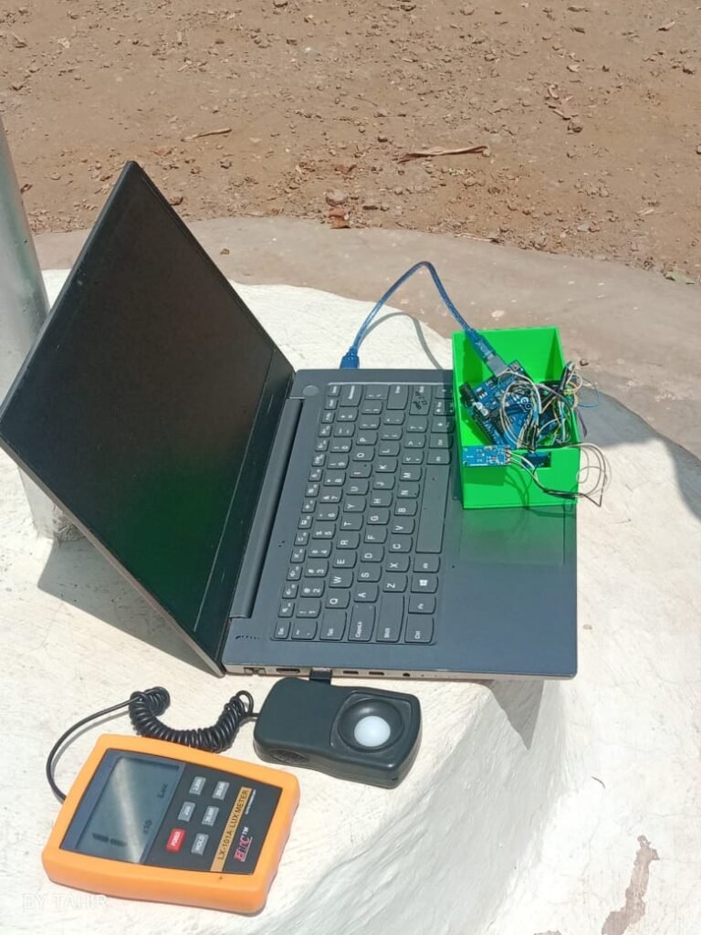
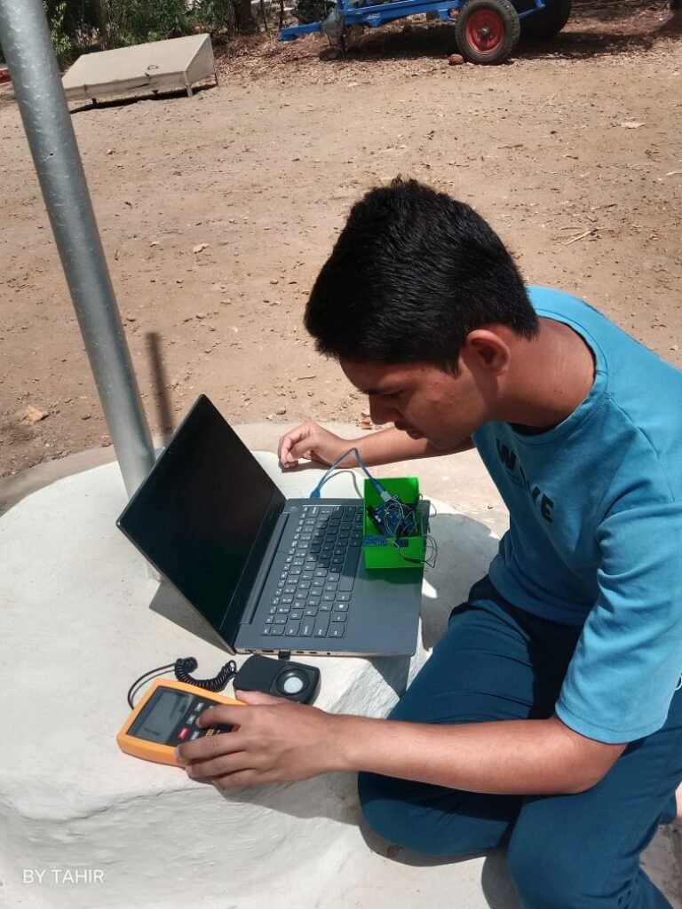
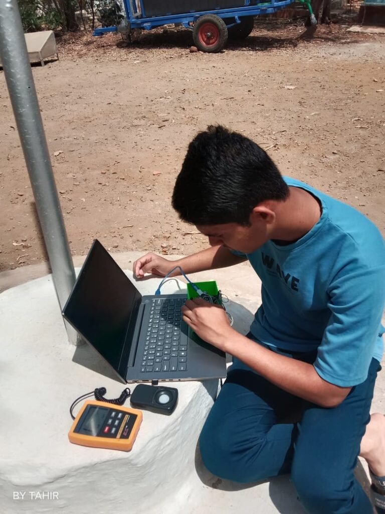
Today, I concentrated on verifying the accuracy of the BH1750 sunlight sensor used in the Sunlight-Based Automatic Roof Control System. To obtain reliable results, I carried the complete hardware setup outdoors, where the sensor could be exposed to natural sunlight under different lighting conditions.
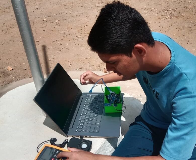
The Arduino UNO was connected to a laptop, and the sensor readings were continuously displayed on the Serial Monitor. Along with the sensor, I used a calibrated digital lux meter as a reference instrument to measure the actual light intensity. Both the BH1750 sensor and the lux meter were placed at the same location and orientation to ensure that they received identical sunlight.
The light intensity values measured by the BH1750 sensor were compared with the lux meter readings at different times and under varying sunlight conditions. During testing, the readings from both devices were found to be very close, confirming that the sensor was providing accurate measurements. This comparison increased confidence in using the BH1750 sensor for automatic roof control based on ambient light intensity.
- Parameter Value
- Roof Weight : 50 kg
- Motion Type : Horizontal Sliding
- Guide Mechanism Metal Rails with Low-Friction Bearings
- Travel Distance : 8 feet (2.44 m)
- Required Travel Time : 30 seconds
- Pulley Radius : 43 mm (0.043 m)
- Gravitational Acceleration (g) : 9.81 m/s²
1. Required Sliding Speed
The roof should travel a distance of 2.44 m in 30 seconds.
The velocity is calculated using:V=TimeDistance V=302.44 V=0.0813 m/s
Calculated Sliding Speed = 0.0813 m/s
This relatively low speed is intentionally selected to ensure smooth operation, minimize mechanical stress, and reduce the required motor power.
2. Weight Force
The gravitational force acting on the roof is calculated using:Fg=m×g
Where:
- Mass (m) = 50 kg
- Gravitational acceleration (g) = 9.81 m/s²
Fg=50×9.81 Fg=490.5 N
Weight Force = 490.5 N
3. Friction Force
Since the roof slides on metal rails fitted with low-friction bearings, a coefficient of friction of 0.04 was assumed.
The friction force equation is:
where:
- μ = coefficient of friction
- N = normal force (equal to the roof weight on a horizontal rail)
- Wheels/rollers on metal rails = 0.02–0.05
- so, we consider μ = 0.04.
The friction force is:Ff=μN Ff=0.04×490.5 Ff=19.62 N
However, practical systems experience additional losses due to:
- Belt transmission losses
- Pulley friction
- Misalignment
- Starting inertia
- Manufacturing tolerances
To account for these real-world conditions, a safety factor of 3 was applied.Fdesign=19.62×3 Fdesign=58.86 N
Design Driving Force = 58.86 N
4. Required Motor Torque
The torque required to rotate the pulley is calculated as:T=F×r
Where:
- Force = 58.86 N
- Pulley Radius = 0.043 m
T=58.86×0.043 T=2.53 N⋅m
Required Torque = 2.53 N·m
5. Torque Conversion
Motor torque is commonly specified in kg·cm, so the calculated torque was converted.1 N⋅m=10.197 kg⋅cm 2.53×10.197 =25.80 kg⋅cm
Applying the same safety factor of 3:25.80×3 =77.4 kg⋅cm
Final Required Torque = 77.4 kg·cm
Based on the above calculations, the motor should be capable of producing at least 77.4 kg·cm of torque. To provide additional reliability and allow for future wear and unexpected loading conditions, a standard motor with a torque rating between 80 and 100 kg·cm (or higher) was selected.
Motor Selection and Ordering :
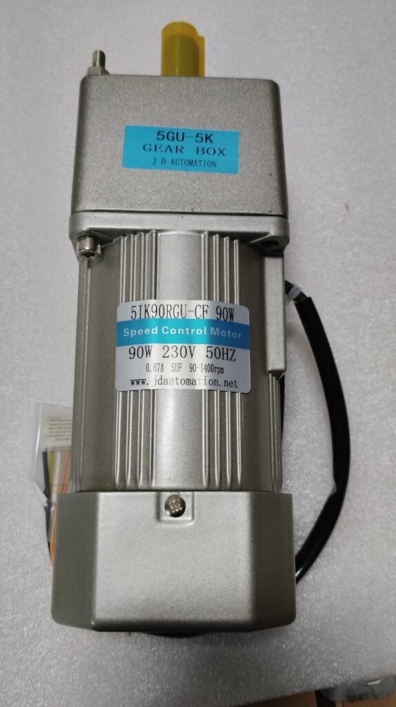
After completing the motor calculations, I selected a motor that meets the required specifications for the automatic sliding roof system. The calculated torque requirement was approximately 77.4 kg·cm, so a 90 W, 230 V AC geared motor with a torque rating suitable for the application was chosen.
The motor was then ordered for the project. It is expected to provide smooth operation, sufficient torque, and reliable performance for opening and closing the sliding roof. This marks an important step toward building and testing the complete automatic roof control system.
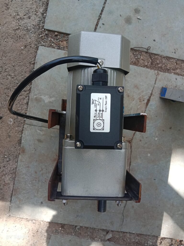
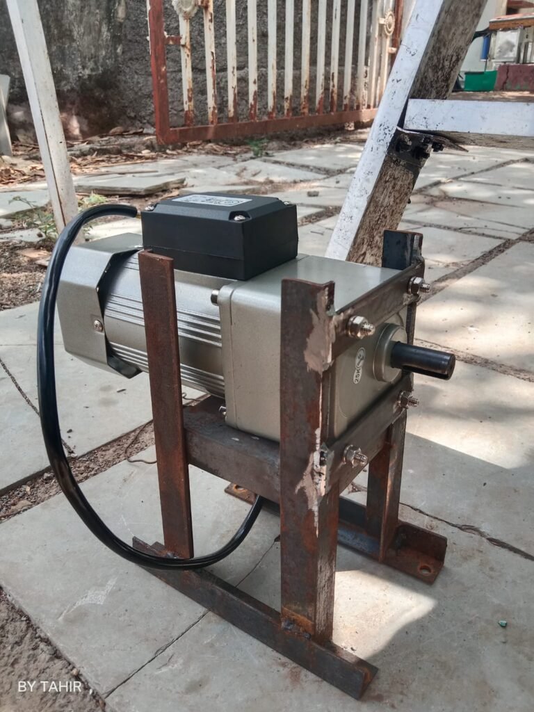
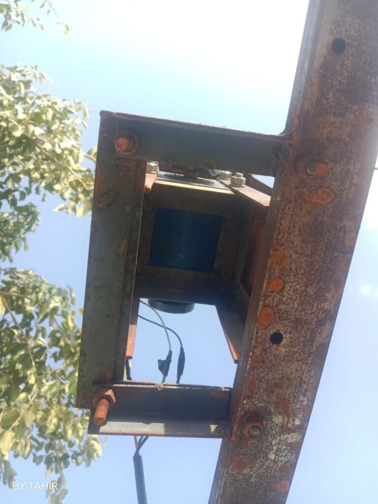
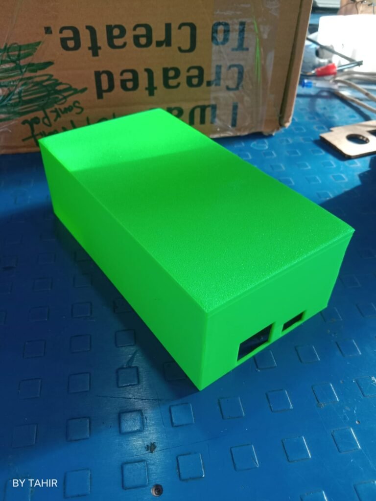
The motor mounting frame was fabricated using mild steel sections and securely welded to ensure proper alignment and stability. The geared motor, relay module, BH1750 sensor, and limit switches were integrated with the Arduino controller. After testing and calibration, the automatic sliding roof system was successfully implemented and operated as intended.
Conclusion :
The development of the sunlight-based roof control system has reached the hardware testing stage. The control logic and program have been completed and verified, and the code functions as expected during software testing. However, the relay module is currently not switching to the ON state, preventing the motor from operating and the system from completing its intended functionality. Further hardware troubleshooting and electrical verification are required before final implementation. This project is being handed over with a working software foundation, allowing the next developer to focus on diagnosing and resolving the remaining hardware issue.