Introduction
Drying vegetables using solar energy is an age-old technique, but modern problems call for modern solutions. To ensure consistent drying, protect nutrients, and eliminate dependency on fluctuating weather, we set out to build a smart solar vegetable dryer. Over the past two weeks, I’ve been working on integrating electronics, sensors, and control systems to make this dryer both efficient and intelligent.
This blog documents the journey, components, challenges, and learnings during the first two weeks of development.
WEEK 1 (3rd June – 10th June)
Existing Timer-Based Fan Control Mode
| Fan | Time of Day | ON Duration | OFF Duration |
|---|---|---|---|
| F1 | Day | 1 min | 2 min |
| F1 | Night | OFF | OFF |
| F2 | Day | 2 min | 2 min |
| F2 | Night | 5 min | 5 min |
Objective
To design and prototype a automatic temperature control for solar-powered vegetable drying system , using an ESP32 microcontroller, AHT2415C temperature sensor, and AC fans (100 and 1000 CFM).
Note: These are trial stages. The final version of the model will incorporate 9 AC fans, a potentiometer for manual control, and a display screen for user interaction.
System Overview:
Key Components:
| Component | Description |
|---|---|
| ESP32 DevKit v1 | Microcontroller unit with Wi-Fi & Bluetooth capabilities |
| AHT2415C | Temperature & humidity sensor with I2C communication |
| AC Fans (100 & 1000 CFM) | High-power airflow units to assist moisture removal |
| Relay Module (Solid State) | Switch to control high-voltage fans via ESP32 |
| Power Supply | Supplies 220V/240V AC to fans; 5V DC to ESP32 |
Block Diagram:
 +-------------------------+
 |     Solar Dryer Box     |
 +-------------------------+
 |                         |
 |  AHT2415C Sensor        |
 |        |                |
 |        v                |
 |    ESP32 DevKit v1      |
 |        |                |
 |        v                |
 |   Relay Module (AC)     |
 |        |                |
 |        v                |
 |     AC Fan (220V)       |
 |                         |
 +-------------------------+
Workflow:
- AHT2415C measures current temperature inside dryer chamber.
- ESP32 reads sensor data and makes decisions.
- If temperature exceeds threshold, ESP32 activates fan via relay.
- Fan cools down chamber, and control loop continues.
Progress Timeline: For week 1
- Research on temperature sensors and microcontrollers
- Chose ESP32 DevKit v1 for its connectivity and ease of programming
- Chose AHT2415C for its accuracy and I2C compatibility
- Setup Arduino IDE for ESP32
- Installed ESP32 board manager
- Verified connection using Blink sketch
- Connected AHT2415C sensor
- Connected using I2C (SDA to GPIO21, SCL to GPIO19)
- Used libraries and confirmed accurate temp/humidity readings
- Relay module integration
- Tested relay with light bulb (worked fine)
- Tried controlling fan via relay — fan didn’t turn on
WEEK 2 (11th June – till date)
Code (for trial 1)
#include <wire.h>
#include <Adsfruit_ATHX0.h>
Adafruit_AHTX0 aht;
const int RELAY_PIN = 18; // Relay control pin
const float TEMP_THRESHOLD = 35; // °C to turn on fan
void setup() {
Serial.begin(115200);
Serial.println("🌡️ AHT + Relay Control");
// I2C init
Wire.begin(21, 19);
if (!aht.begin()) {
Serial.println("❌ AHT sensor not found!");
while (1) delay(10);
}
pinMode(RELAY_PIN, OUTPUT);
digitalWrite(RELAY_PIN, LOW); // Start with fan OFF
Serial.println("✅ System ready.");
}
void loop() {
sensors_event_t humidity, temp;
aht.getEvent(&humidity, &temp);
float temperature = temp.temperature;
Serial.print("🌡️ Temperature: ");
Serial.print(temperature);
Serial.println(" °C");
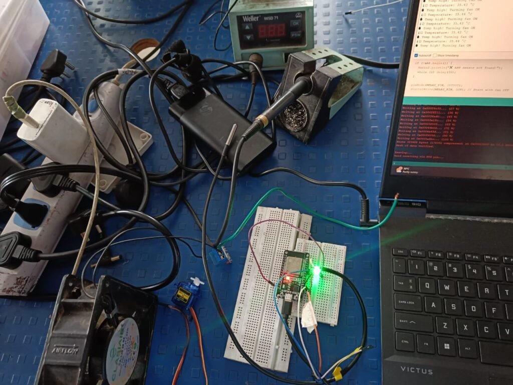
if (temperature > TEMP_THRESHOLD) {
Serial.println("🔥 Temp high! Turning fan ON");
digitalWrite(RELAY_PIN, HIGH); // Relay ON → Fan ON
} else {
Serial.println("✅ Temp normal. Fan OFF");
digitalWrite(RELAY_PIN, LOW); // Relay OFF → Fan OFF
}
delay(200);
}Progress Timeline: For week 2
- Diagnosed fan issues
- Cross-checked wiring, relay functionality
- Found relay not compatible with fan’s high inductive load
- Fan worked once and then stopped
- The relay got burnt
- Did research to find which solid-state relay (SSR) would be suitable based on fan specifications: Focused on choosing a suitable SSR
- Compared SSR models that support inductive AC loads
- Evaluated current, voltage, and heat dissipation requirements
- Yet to receive and test the SSR — currently in the research and selection phase
Current Setup Snapshot
| Module | Connection Details |
| ESP32 to Sensor | SDA -> GPIO21, SCL -> GPIO19 |
| ESP32 to Relay | GPIO18 (Digital pin) -> IN of Relay |
| Relay to Fan | AC live wire through relay, neutral direct |
Fan Successfully Operated via 5V Relay
- Rebuilt the fan control circuit using a standard 5V relay.
- Fan responded correctly to ESP32 commands based on temperature threshold.
- Added a flyback diode across the relay coil to protect against voltage spikes.
- Relay remained stable across multiple ON/OFF cycles.
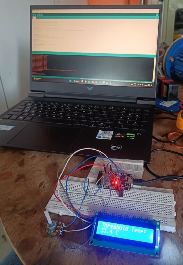
Potentiometer Integration
- Connected a potentiometer to an analog pin on the ESP32.
- Mapped potentiometer values to control the temperature threshold dynamically (e.g., 30–50°C).
- This allows for real-time adjustment of the drying condition without reprogramming.
OLED Display Setup
- Interfaced an I2C OLED (SSD1306) to ESP32 for real-time feedback.
- Display now shows:
- Current temperature
- Set threshold (from potentiometer)
- Fan status (“ON” or “OFF”)
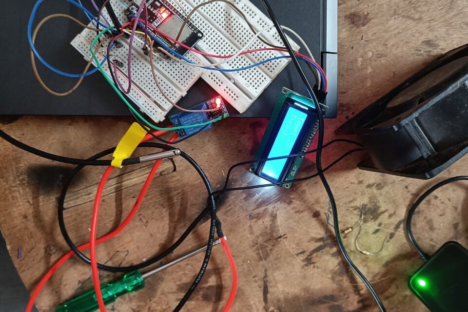
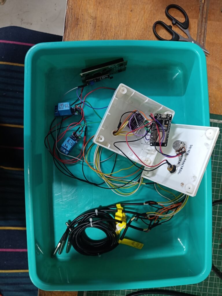
Full Circuit Assembly and Testing
- Connected all components: ESP32, AHT2415C, relay, AC fan, potentiometer, and OLED display.
- Verified that temperature readings are accurate, threshold updates in real-time, and fan control logic is functioning as intended.
- Serial monitor used alongside OLED for debugging.
Stability Observation
- Ran the complete circuit continuously for several hours (no load drying test).
- Observed consistent readings and smooth operation of relay and display.
- No overheating or instability in relay or ESP32.
Wiring Details
AHT20 Sensor (Temperature & Humidity Sensor)
- VCC → ESP32 3.3V (or 5V if the module supports it)
- GND → ESP32 GND
- SDA → ESP32 GPIO 21
- SCL → ESP32 GPIO 22
16×2 I2C LCD (Address 0x27)
- VCC → ESP32 5V (Usually LCDs require 5V for proper backlight)
- GND → ESP32 GND
- SDA → ESP32 GPIO 21
- SCL → ESP32 GPIO 22
Note: The LCD and AHT20 share the same I2C bus, which is normal and supported.
Potentiometer (10kΩ recommended)
- Left pin → ESP32 3.3V
- Right pin → ESP32 GND
- Middle pin (wiper) → ESP32 GPIO 34
GPIO 34 is input-only, perfect for analog input. Do not connect outputs to it.
Relay Module (Active LOW type)
- VCC → ESP32 5V
- GND → ESP32 GND
- IN → ESP32 GPIO 18
Code (for trial 2)
#include <Wire.h>

#include <Adafruit_ATX0.h>

#include <LiquidCrystal_I2C.h>

// Objects
Adafruit_AHTX0 aht;
LiquidCrystal_I2C lcd(0x27, 16, 2);

// Pins
const int potPin = 34; // Potentiometer pin
const int relayPin = 18; // Relay control pin

void setup() {
Wire.begin(21, 22); // I2C pins for ESP32
Serial.begin(115200);

// Initialize LCD
lcd.begin(16, 2);
lcd.backlight();

// Initialize AHT sensor
if (!aht.begin()) {
lcd.setCursor(0, 0);
lcd.print("AHT not found!");
while (1) delay(10);
}

// Initialize relay pin
pinMode(relayPin, OUTPUT);
digitalWrite(relayPin, HIGH); // Relay OFF by default (active LOW)
}

void loop() {
// Read potentiometer and map to threshold range
int potVal = analogRead(potPin); // 0–4095
float thresholdTemp = map(potVal, 0, 4095, 200, 500) / 10.0;

// Read actual temperature from AHT
sensors_event_t humidity, temperature;
aht.getEvent(&humidity, &temperature);
float actualTemp = temperature.temperature;

// Relay logic
if (thresholdTemp<= actualTemp) {
digitalWrite(relayPin, LOW); // Turn ON relay (active LOW)
} else {
digitalWrite(relayPin, HIGH); // Turn OFF relay
}

// Display data on LCD
lcd.clear();
lcd.setCursor(0, 0);
lcd.print("Temp: ");
lcd.print(actualTemp, 1);
lcd.print(" C");

lcd.setCursor(0, 1);
lcd.print("Thresh: ");+
lcd.print(thresholdTemp, 1);
lcd.print(" C");

delay(1000);
}
Designing a Custom PCB for the Solar Vegetable Dryer Control System
After validating the working of the circuit on a breadboard, the next logical step was to design a Printed Circuit Board (PCB) to make the system compact, robust, and ready for real-world deployment. Breadboards are great for prototyping, but they are neither durable nor reliable for long-term applications — especially in a solar dryer setup where heat, vibration, and moisture are often present.
Why a Custom PCB?
A custom PCB helps:
- Ensure stable electrical connections (no loose wires)
- Reduce electromagnetic noise that can affect sensor readings
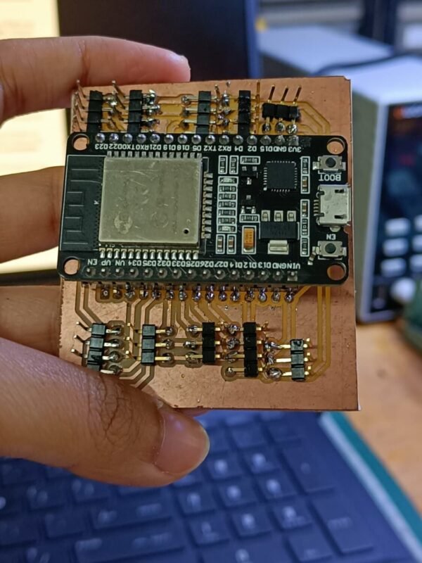
- Provide mechanical support for all components
- Improve overall system aesthetics and integration
This step was especially important for us because the system has to operate autonomously and continuously, monitoring drying conditions (like temperature and humidity) and adjusting airflow accordingly.
Tools Used: KiCad
To design the PCB, I used KiCad, an open-source PCB design suite. It provides a full flow from schematic capture to layout and 3D visualization — and has enough flexibility to handle both simple and moderately complex designs.
Designing the Schematic
The circuit includes:
- 2 Relays to control heating elements and fans
- 4 Sensors (e.g., temperature, humidity)
- 1 LED screen to display real-time data
- 1 Potentiometer for setting target thresholds
- And an ESP32 microcontroller as the brain of the system
Each component was added in KiCad’s schematic editor, with special care taken to:
- Assign clear and meaningful net labels
- Place pull-up resistors on I2C lines
- Add decoupling capacitors near critical components
- Include flyback diodes across relay coils to suppress voltage spikes
Assigning Footprints and Layout
Once the schematic was complete, the next step was assigning footprints to each component. I used KiCad’s official and community footprint libraries to select appropriate packages:
- Pin headers for sensor and display modules
- Screw terminals for power and relay connections
- DIP/SMD packages for resistors, capacitors, and the ESP32
In the PCB layout editor, I placed components keeping in mind:
- Shortest possible signal paths between sensors and ESP32
- Power and ground traces wide enough to handle current
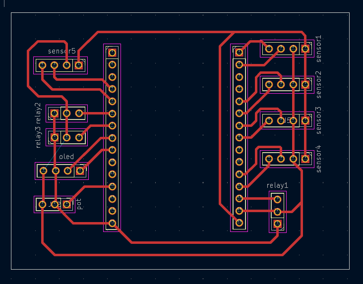
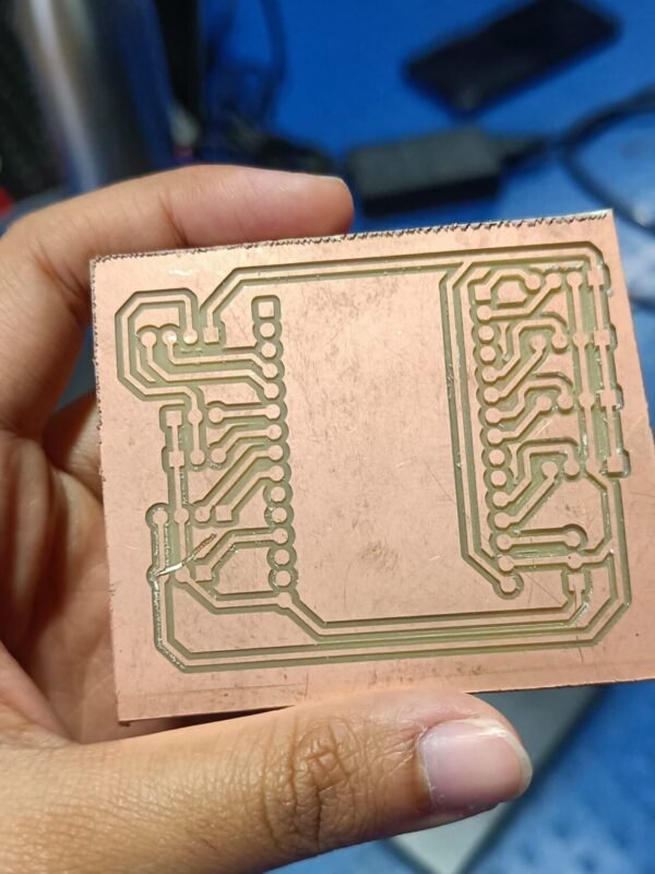
Finalizing the Design
After running Electrical Rule Checks (ERC) and Design Rule Checks (DRC), I generated Gerber files and used KiCad’s 3D viewer to inspect the final board layout. The board is now ready for fabrication and mounting into the solar dryer setup.
Multi-Sensor Integration with Multiplexer and Intelligent Relay Logic
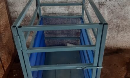
As the system matured, it became clear that a single-point temperature reading was insufficient for accurate control in a solar vegetable dryer. The drying chamber experiences uneven heat distribution due to varying airflow, solar intensity, and load placement. To address this, Iteration 3 introduces a multi-zone temperature monitoring system, powered by a multiplexer and intelligent relay control logic.
This iteration aims to:
- Measure temperature at multiple points within the dryer dome
- Enable zone-based decision making
- Improve drying uniformity and system responsiveness
- Maintain user control through an adjustable threshold
- Provide real-time display of system data
System Overview
In this version, the ESP32 interfaces with four AHT2415 sensors, all having the same I²C address. To solve the address conflict, a TCA9548A I²C multiplexer was introduced. This allowed the controller to communicate with each sensor individually over different channels.
A 16×2 I²C LCD was added to show temperature readings, ΔT (temperature difference), and the current threshold set via a potentiometer.
The two relays control top and side exhaust fans, based on temperature patterns detected across the dome.
🔧 Hardware Components
| Component | Description |
|---|---|
| ESP32 DevKit | Central controller |
| TCA9548A | 8-channel I²C multiplexer to connect sensors with identical I²C addresses |
| AHT2415 Sensors (x4) | Digital temp/humidity sensors installed in different zones |
| Relay Module (x2) | Controls top and side exhaust fans |
| Potentiometer | User-controlled threshold input (0–40°C) |
| 20×2 LCD (I²C) | Displays sensor readings, threshold, and system status |
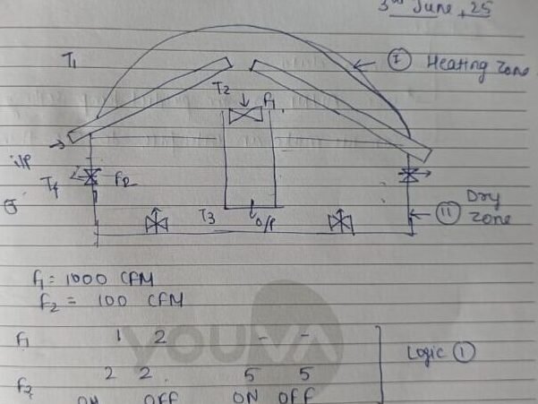
System Logic
Relay 1 (Top Fans)
- Measures ΔT = T1 − T0
- If ΔT < Threshold → Relay 1 ON (fans active)
- Else → Relay 1 OFF
Relay 2 (Side Fans)
- Checks: T1 > T2 > T0 ≥ T3
- If condition is True → Relay 2 ON
- Else → Relay 2 OFF
- Threshold Control
- Potentiometer connected to analog input (GPIO 25)
- Maps ADC values (0–4095) to temperature threshold (0–40°C)
- Allows the user to dynamically set the system’s sensitivity without reprogramming
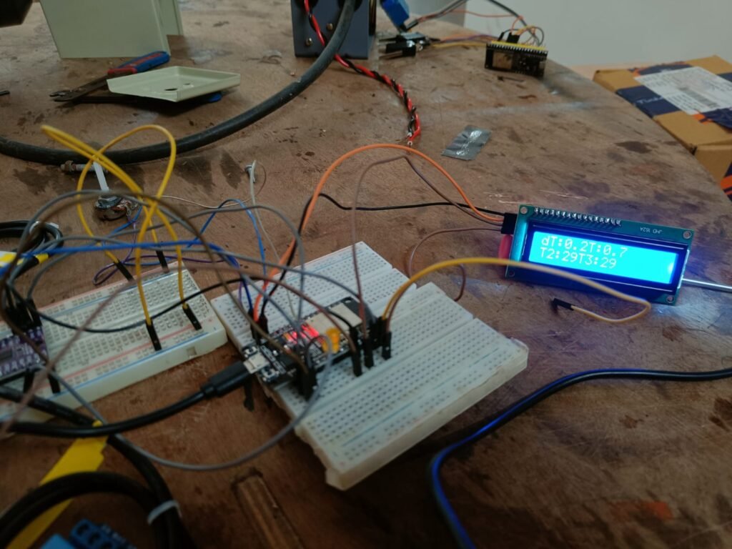
Display Logic
- Row 1: Shows current ΔT and user-set threshold
- Row 2: Cycles between displaying (T0, T1) and (T2, T3) every 3 seconds
- Helps the user monitor how each zone is behaving in real-time
Pin Configuration
| Function | GPIO Pin |
|---|---|
| TCA9548A SDA | GPIO 21 |
| TCA9548A SCL | GPIO 22 |
| LCD SDA | GPIO 21 |
| LCD SCL | GPIO 22 |
| Relay 1 Control | GPIO 35 |
| Relay 2 Control | GPIO 34 |
| Potentiometer (Analog) | GPIO 25 |
Software Enhancements
- Modular code structure for sensor polling across multiplexer channels
- Clean separation of logic for relay decisions
- Potentiometer input mapped using: cppCopyEdit
thresholdC = map(analogRead(POT_PIN), 0, 4095, 0, 40); - Robust I²C error handling and delay optimization to avoid lock-ups or collisions
Final code:
#include <Wire.h>
#include <Adafruit_AHTX0.h>
#include <LiquidCrystal_I2C.h>
#include <math.h>

// === I2C Address ===
#define TCA_ADDR 0x70

// === Sensors ===
Adafruit_AHTX0 sensors[4];
float temperatures[4];

// === LCD ===
LiquidCrystal_I2C lcd(0x27, 20, 2);  // LCD on default Wire (SDA=21, SCL=22)

// === Pins ===
#define RELAY1_PIN 18
#define RELAY2_PIN 5
#define POT_PIN    25

float tempThreshold = 2.0;
unsigned long lastFlip = 0;
bool showT0T1 = true;

void tca_select(uint8_t channel) {
  if (channel > 7) return;
  Wire.beginTransmission(TCA_ADDR);
  Wire.write(1 << channel);
  Wire.endTransmission();
}

void setup() {
  Serial.begin(115200);
  Wire.begin(21, 22);  // I²C for all devices: MUX, LCD, sensors

  pinMode(RELAY1_PIN, OUTPUT);
  pinMode(RELAY2_PIN, OUTPUT);
  digitalWrite(RELAY1_PIN, HIGH);
  digitalWrite(RELAY2_PIN, HIGH);

  lcd.init();
  lcd.backlight();
  lcd.clear();
  lcd.setCursor(0, 0);
  lcd.print("Init Sensors...");

  for (uint8_t i = 0; i < 4; i++) {
    tca_select(i);
    delay(100);
    if (!sensors[i].begin()) {
      Serial.print("❌ Sensor fail at ch ");
      Serial.println(i);
    } else {
      Serial.print("✅ Sensor OK at ch ");
      Serial.println(i);
    }
  }

  lcd.clear();
}

void loop() {
  // === Read Potentiometer for threshold ===
  int raw = analogRead(POT_PIN);
  tempThreshold = map(raw, 0, 4095, 0, 4000) / 100.0;  // → 0.00–40.00 °C

  // === Read all Sensors ===
  for (uint8_t i = 0; i < 4; i++) {
    tca_select(i);
    delay(10);

    sensors_event_t hum, temp;
    sensors[i].getEvent(&hum, &temp);
    temperatures[i] = temp.temperature;

    Serial.print("T");
    Serial.print(i);
    Serial.print(": ");
    Serial.print(temperatures[i], 1);
    Serial.println(" C");
  }

  float T0 = temperatures[0];
  float T1 = temperatures[1];
  float T2 = temperatures[2];
  float T3 = temperatures[3];
  float deltaT = fabs(T1 - T0);

  // === Relay 1 Logic ===
  if (deltaT > tempThreshold)
    digitalWrite(RELAY1_PIN, LOW);
  else
    digitalWrite(RELAY1_PIN, HIGH);

  // === Relay 2 Logic ===
  bool relay2_condition = (T1 > T2) && (T2 > T0) && (T0 >= T3);
  digitalWrite(RELAY2_PIN, relay2_condition ? LOW : HIGH);

  // === OLED Display ===
  lcd.clear();
  lcd.setCursor(0, 0);
  lcd.print("dT:");
  lcd.print(deltaT, 1);
  lcd.print(" T:");
  lcd.print(tempThreshold, 1);

  if (millis() - lastFlip > 3000) {
    showT0T1 = !showT0T1;
    lastFlip = millis();
  }

  lcd.setCursor(0, 1);
  if (showT0T1) {
    lcd.print("T0:");
    lcd.print(T0, 1);
    lcd.print(" T1:");
    lcd.print(T1, 1);
  } else {
    lcd.print("T2:");
    lcd.print(T2, 1);
    lcd.print(" T3:");
    lcd.print(T3, 1);
  }

  delay(3000);
}

