INTRODUCTION
This was the first assignment that was given to me on very first day of my 4 month In-Plant training in Vigyan Ashram. It was given by Prasad Patil sir on 15/08/2024. This assignment was based on Solidwork which is the software that I learnt in the 1 month training at IGTR.
DESCRIPTION
This was our first assignment in the Vigyan Ashram just to get use to the process of designing. As during our interview we were asked about what we have learned in our previous training. So we told the courses we did the previous month which was Solidworks. And also in the mess of the ashram stands for vessels were needed so taking these points under consideration prasad sir decided to give us our first assignment as designing of the vessel stands. As we were the group of four so he told us to make four different designs and one of the design was to be finalised.
16/08/2024
Firstly, we went to the mess to take the dimensions of the vessels for which we wanted to design a stand. Then we took all the measurements of the vessels including a Plate, Bowl and Spoon. The measurements we took were as follows:
For Plate: Diameter = 33cm , Height = 2cm
For Bowl: Diameter = 7.7cm , Height = 3.8cm
For Spoon : Lenght = 15.5cm , Width = 3.6cm
Not only this but for the convenience of the design of the stand we also took the dimensions of the previous stands which were noted as 26cm in length and 15.2 cm in width
17/08/2024
After taking the measurements and dimensions of vessels and the old stand Prasad sir told us to make a rought design one our notebook of our own and all the design should be different from one another. So we started making our designs. For that I took the reference of the dimensions that I took and depending upon the dimensions I designed a stand. While making the design I made one slot for the plate. The diameter of plate that I measured was 33cm so i kept the length of the slot 20cm so as to keep the plate partially penetrated into the slot and as the thickness of the plate was 2cm I kept the thickness of the slot as 2.5 cm to allow the plate to freely pass through it.
similarly, by taking same points in mind I created a slot for spoon as well. And for bowl I made a L shaped structure on the right side edge which is lifted 4cm for hanging the bowl. In this way I finished my rough design
18/08/2024
After the rough sketch was completed we showed it to Prasad sir. Then he told us to make calculation on how much will be the pressure of all the vessels and what is the bearing capacity of our respective structures. So we made the calculations as per shown below :
CALCULATION :
Force = Mass * Acceleration = 0.600*9.8= 5.88 kg m/s = 5.88 N
Also Area = Length * Width = 0.265*0.15 = 0.03975 m^2
Now, Pressure = Force / Area = 5.88 / 0.03975 = 147.95 N/m^2
By taking some pressure of water assume approximately Pressure = 200 N/mm^2
This is the pressure that will act on the stand
Now, let us calculate Ultimate Stress , by assuming F.O.S as 2
As we know Ultimate Stress = Allowable Stress * Factor of Safety = 200*2 = 400 N/m^2
20/08/2024
Till now we had found out the dimensions of the design, ultimate stress and also figured out the material of the design which is MS sheet. But there was one thing missing which was IMP to create a model in Solidworks which we had not found till now was the thickness of the sheet.
we found the thickness of sheet metal by refering this chart :
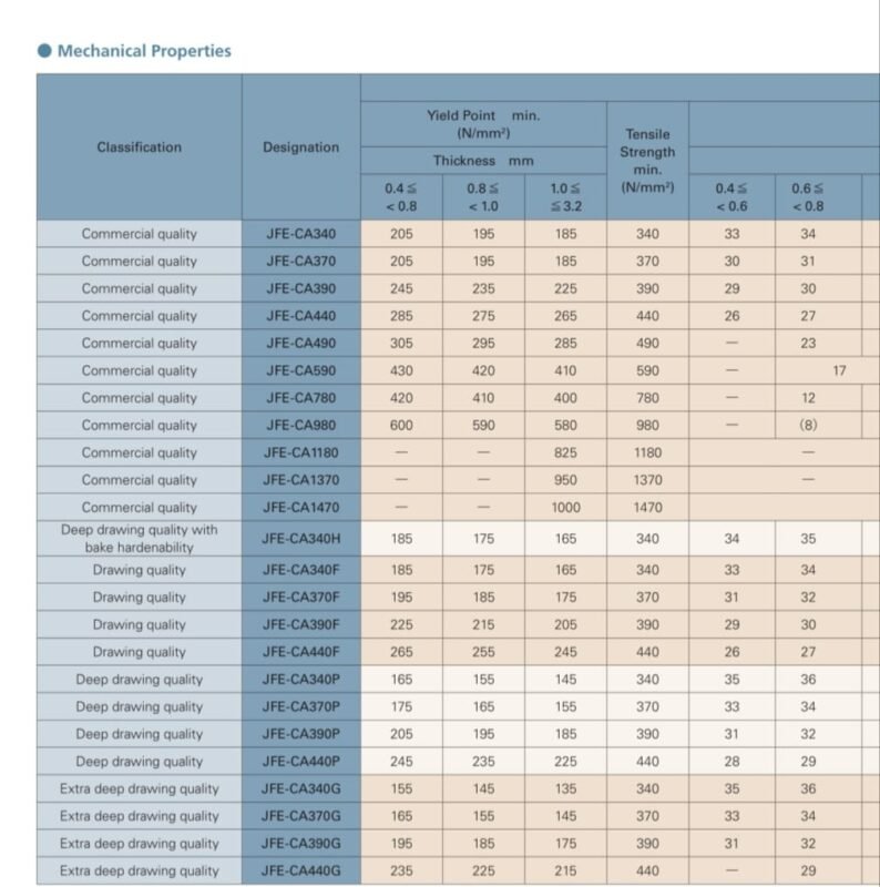
So for finding that we used the ISO sheet for MS sheet. As the ultimate stress for our design was 400 N/m^2 which we converted to N/mm^2 which is 0.004 N/mm^2.This value is much smaller than that of the lowest value in the ISO sheet for MS sheet so we took the smallest range of thickness of the sheet which was 0.4mm < 0.8 mm. At that time in the market 0.8 mm sheet was only available so we purchased 0.8 mm sheet for the design.
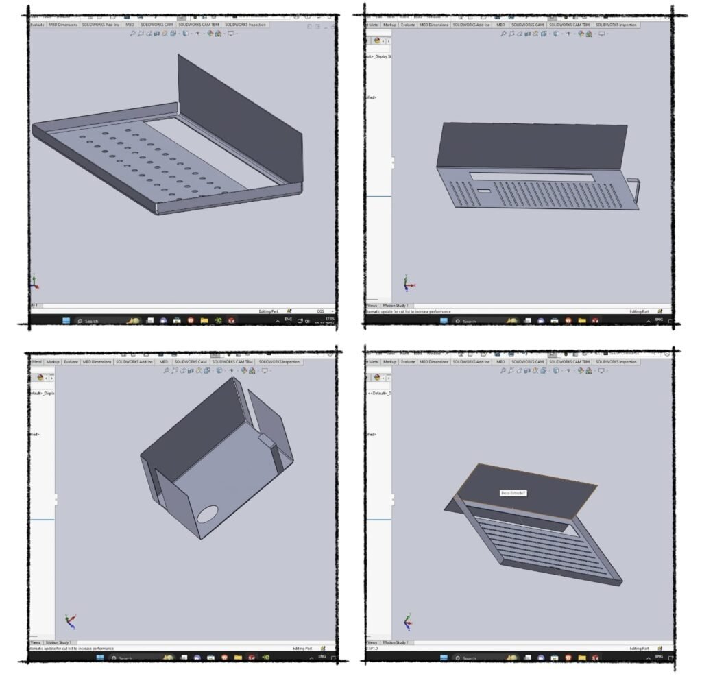
After all the dimensions were decided we started creating the model on the Solidworks software. Following is the model that I created:
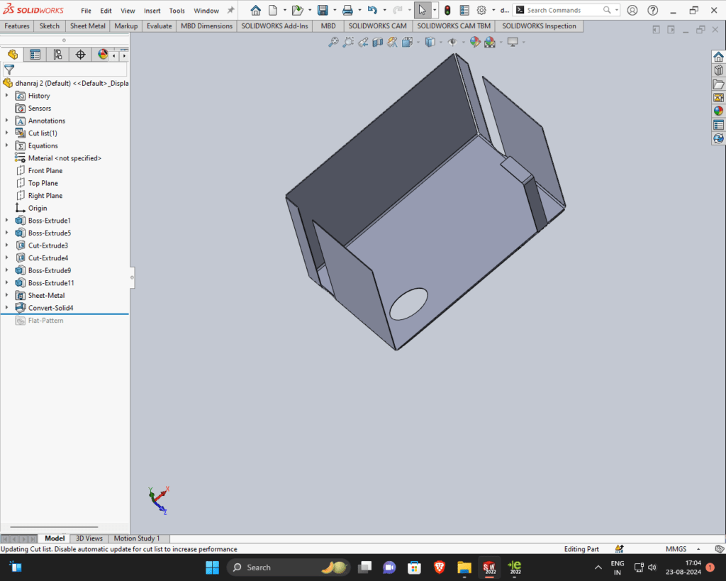
After creation of this model we converted it into sheet metal because we were going to use Plasma cutter to cut the sheet in desired shape.
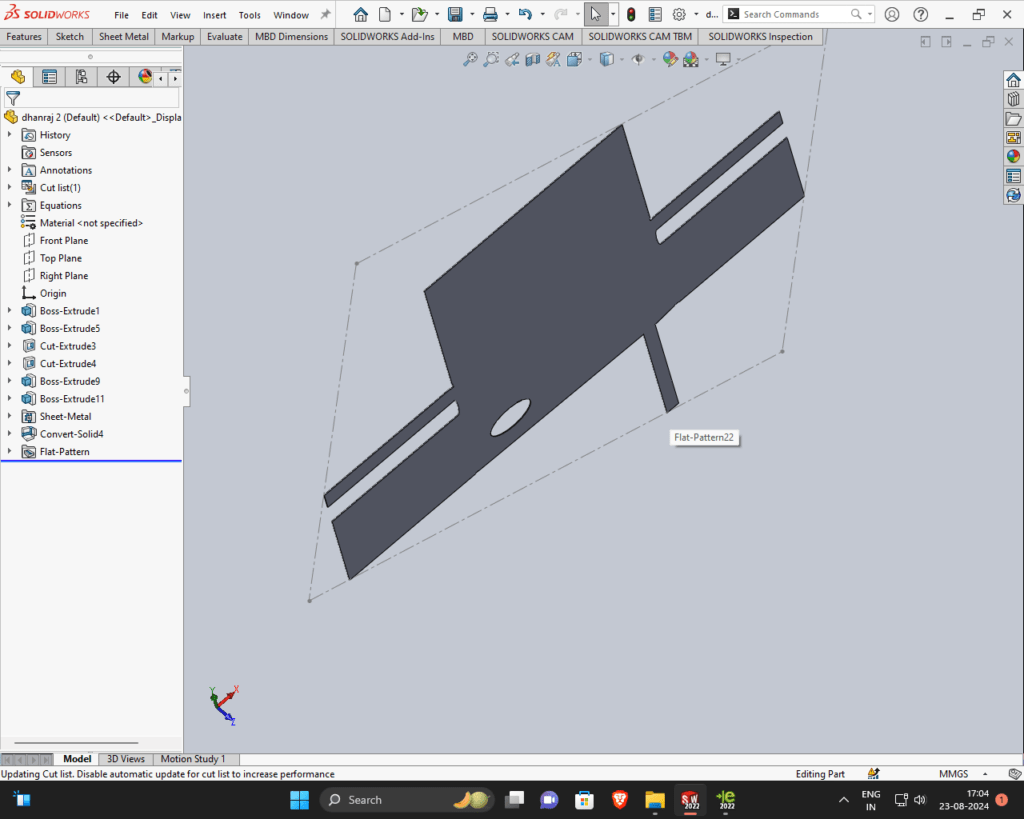
Given below is the flattened form of the model :
21/08/2024
After creation of model I showed it to Prasad sir. Then the next step he told us to estimate the cost that will be required for making the model. firstly we are find out the area of the flat metal model. But in Solidwork , the area is given by going to the evaluate command and then going to measure. So the area did not have to be findout.
Calculations For Cost Estimation: Net Weight = Total Volume * Density of MS
Total Volume : Area * Thickness = 122152.65mm^2 * 0.8 = 97722.12mm^3
Net Weight = 97722.12mm^3 * 7.8*10^-6
= 9.7722*7.8*10^-6*10^4 kg
Net Weight = 0.77 kg/mm^3
Now, Cost of MS steel per kg = Rs 65
Cost for 0.77 kg Mild Steel = 65* 0.77 =Rs 50.05
23/08/2024
Till this day the CAD design of the stand was finalised. The next step Prasad sir told us to cut the flat design of the stand on a cardboard by using Laser Cutter Machine. For that we had to save the CAD file in Dxf extension. After that we copied the Dxf file in the pendrive and went to Fab Lab. Then we put the file in the RD works software to make the RD file and also set the speed and power of the laser cutter. Power given was 90% and speed 30 mm/s. After that we removed the pendrive and attached to the Laser Cutter machine. then next procedure given below:
On the Main Switch > Isolation Transformer > On Stabilizer > On Industrial Cooler > On Main Laser Machine Switch > On Emergency Switch > On Lamp > Going to the file > Select the Udisk^+ > Select the Read Udisk > Select the Copy to Memery > Esc > On Exhaust Switch > On Laser Switch > Select Frame > Select Origin > START.
24/08/2024
As we were four working together so each of us made 4 different model in solidworks software and 4 different cardboard models of them which are given below
After we cut the cardboard model on laser cutter we showed it to prasad sir. Then Prasad sir told us that there are some mistakes in everyone design. Then he asked to make a new design in the group. After that we discussed and make a design in the book.Then we took the dimensions of the vessels and gave them them a rough design. After giving the dimension we drew the model in solidwork software.
25/08/2024
On this day , we will discuss the type of stress applied on the stand being made. Then Prasad sir and Dixit sir explained the stresses to us.
1.Tensile stress: The ratio of increase in length to original length of the body when it is subjected to pull force.
2.compressive stress : Ratio of decrease in length to original length of the body when it is subjected to a pull force.
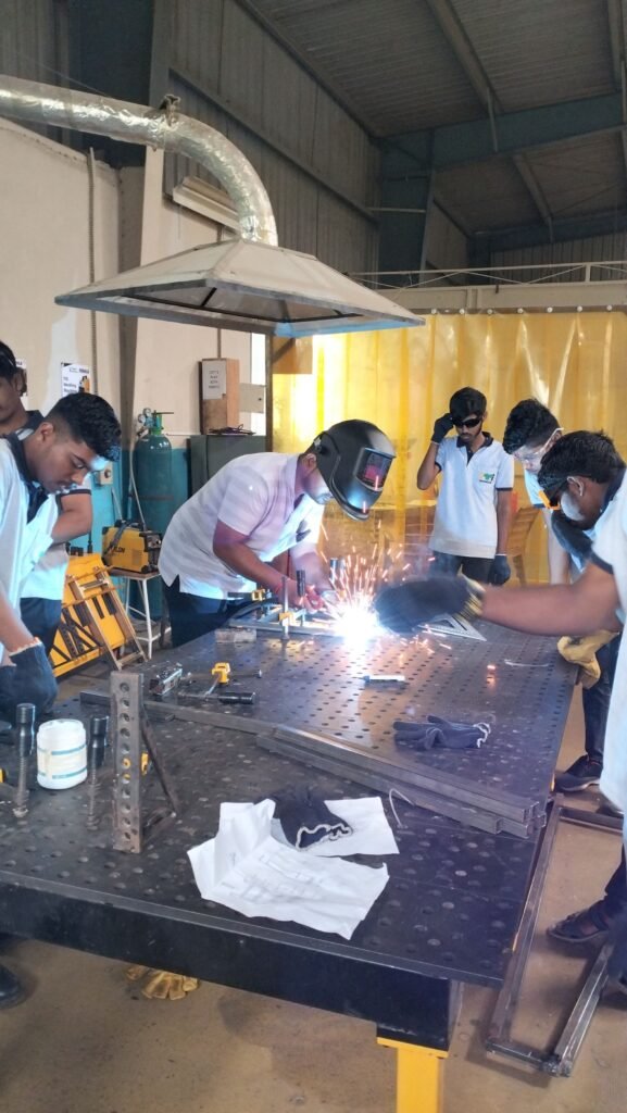
After that we learned about types of welding in workshop.
Types of welding in workshop :
1.Co2 gas welding : CO2 welding, also known as MAG (Metal Active Gas) welding, is a variation of MIG welding that uses carbon dioxide (CO2) as a shielding gas. Here are some things to know about CO2 welding.
Works : A welding wire is fed into the weld pool by a welding torch and melts together with the molten pool. The CO2 gas shields the weld pool from oxygen and nitrogen in the atmosphere
2.ARC welding : Arc welding is welding using the heat of an arc as a heat source. In arc welding, positive voltage is applied to the electrode and negative voltage is applied to the base material. This makes an arc occur from the base material to the electrode.
After that save the model in DXF file and then take the file in pendrive. Then before cutting the laser cutter, import DXF file and then set it’s speed and power in rdworks software . Power given was 90% and speed was 30mm/s.Then put the cardboard in laser cutter and then started the machine . For the cutting process we connected the pen drive to the laser cutter and copied the RD fine in the laser cutter for doing that we clicked on file button provided on Laser cutter machine the selected option U Disc > Read U disk > Copy to memory > Enter. After that we framed the Laser cutter just to get an idea whether the Laser goes out of the trajectory of our design by clicking frame button. Then we switched on the laser and started cutting. In this way we obtained the rough model of the stand.
26/08/2024
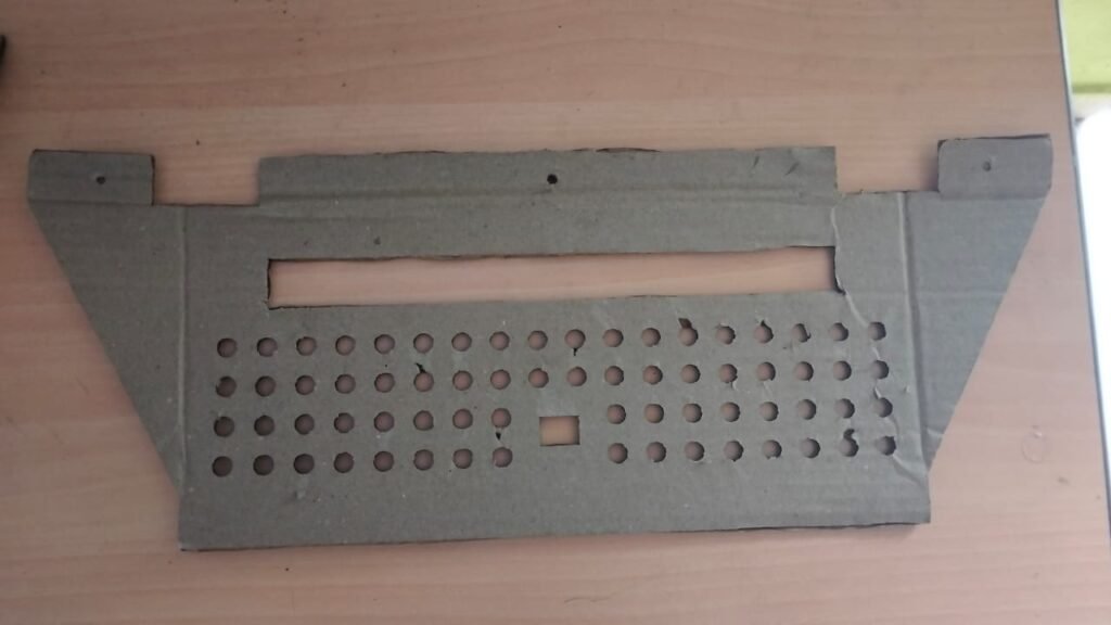
On this day we had discussion about the model that we cut on the laser cutter and Mahesh sir told us to make the slots for the screw. Then we went to kitchen to get and idea from the previous design at that positions we have to create slots for the screws. Then we edited the design again in solidworks and added the slots for the screws. In this design we arranged the vessels and also came to know that the length of the slot for the plate is large that the plate was slipping through the . So we decreased the length of the slot as well. Earlier it was 32 cm and we edited it to 30 cm. Then we again Laser cut on the cardboard using Laser Cutter by repeating same previous process. Following is the model that was created :
After creation of model we were told to estimate the cost of the material required so we estimated the cost.
CALCULATION :
Net Weight = Total Volume * Density of MS
Total Volume : Area * Thickness = 76899.29 mm2 * 0.8 mm = 61519.432 mm3
Net Weight = 61519.432 mm3 * ( 7.8 * 10-6 Kg/mm3)
Net Weight = 0.47 kg
Now, Cost of MS steel per kg = Rs 65
Cost for 0.34 kg Mild Steel = 65 * 0.47 = Rs 30.55
02/09/2024
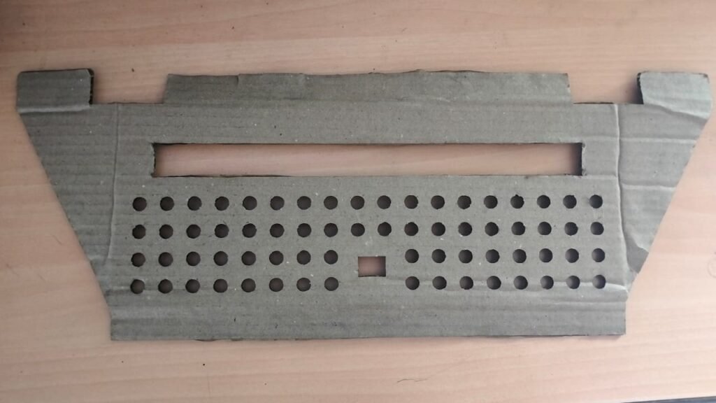
On this day we showed the previous model to Prasad sir and a small discussion happened where he highlighted another problem that in this current design the after keeping the plate in slot it will touch the wall. And he set another condition that modify the design in such a way that the plate after keeping in the slot should not touch the wall. So we started modifying the model again on solidworks. After we made the required changes again we converted the file into dxf file and repeated the previous same procedure for laser cutting in Fab Lab.
Following was the model obtained :
After completion of the design we were told to estimate the cost of this new design. So we estimated the cost by doing same calculations as before which are mentioned below :
CALCULATION :
Net Weight = Total Volume * Density of MS
Total Volume : Area * Thickness = 111276.93 mm2 * 0.8 mm = 89021.544 mm3
Net Weight = 89021.544 mm3 * ( 7.8 * 10-6 Kg/mm3)
Net Weight = 0.70 kg
Now, Cost of MS steel per kg = Rs 65
Cost for 0.34 kg Mild Steel = 65 * 0.70 = Rs 45.5
03/09/2024
Again we showed the new model created to the Prasad sir and then he told us to bring some more modifications in the new design and also focus on some cost cutting. So we again edited this new design and we came to know that the part that we created to hold the plate and avoid it from touching the wall contains a lot of unnecessary material which results in increase in the cost. So we decided to remove the unnecessary material from that part.
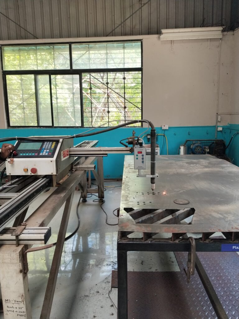
24/09/2024
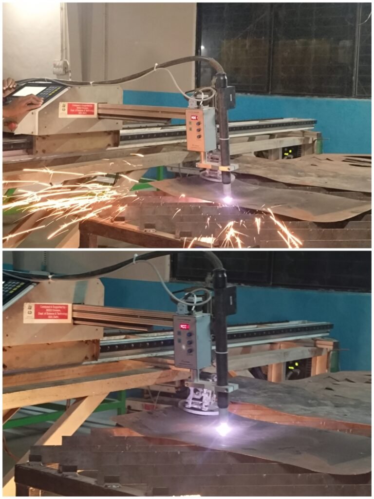
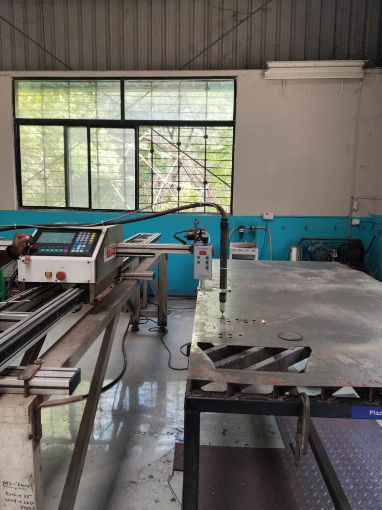
I went to the plasma cutting machine in the workshop for the design cutting of whatever stand was designed. But we took the old sheet for cutting because the machine was off for a long time. But while cutting, I realized that it comes down in the nozzle itself, so the cutting was not done properly.So with the help of Prasad sir, we tried to cut the sheet, and we also tried it by running it a bit.
25/09/2024
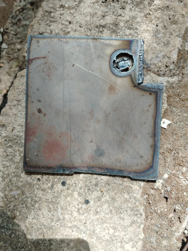
As the plasma machine repair was done, we all went to the workshop for cutting with Mahesh sir. First we learned the plasma cutting machine and learned how to handle it and we cut a design on it, and then started cutting again on the old sheet as a try. But due to more holes in our design, they were touching each other and the cut was not done properly.So we went to update that design again.
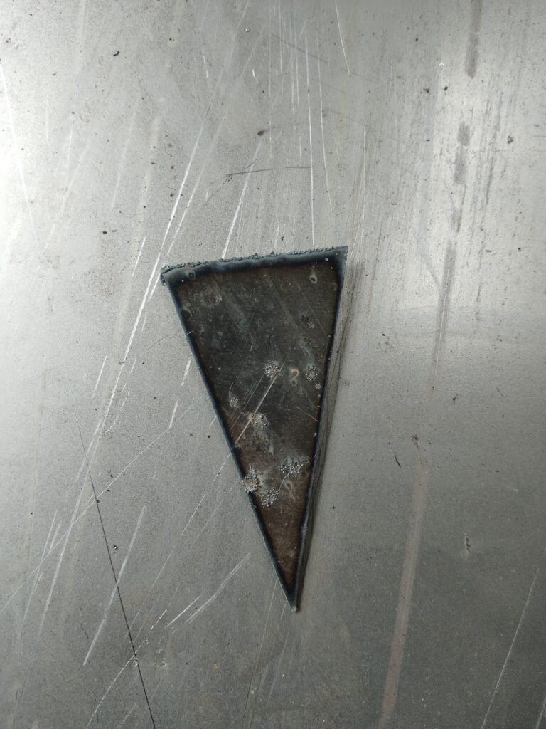
27/09/2024
Tried cutting first on a lot of sheets, but it was not cutting properly. So after that there was already a new sheet in the ashram, it was used. For plazma cutting machine, it is always necessary to have a plane sheet because the cutting is proper if it is plane. Then we got all the sheets cut through Mahesh sir.
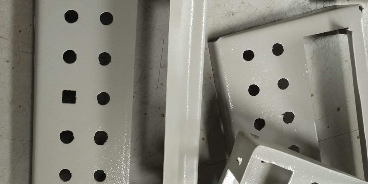
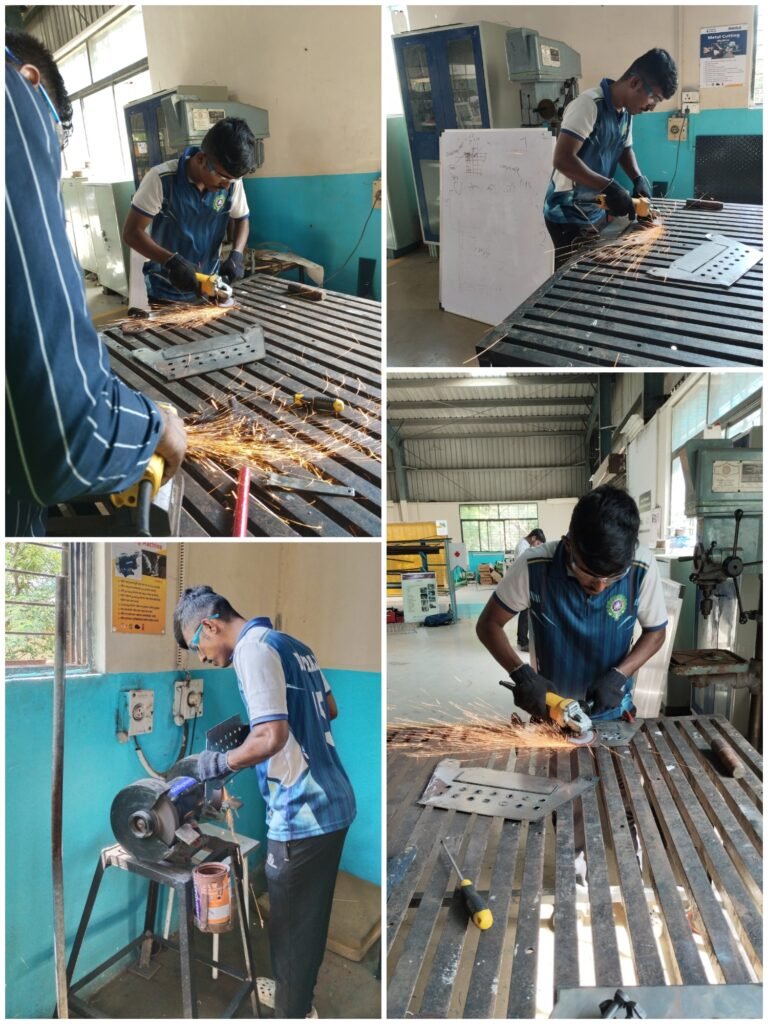
28/09/2024
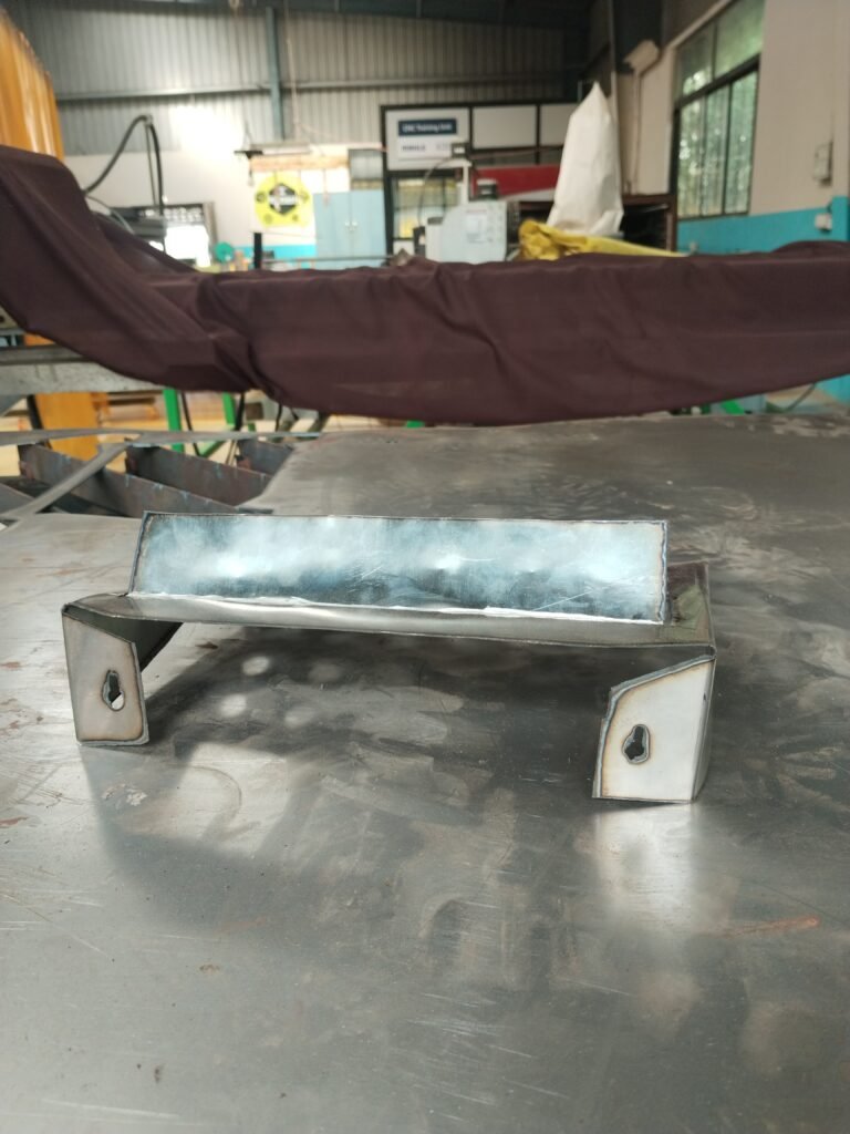
The vessel stand which we cut was now to be grinded. Because when any material is cut on the plasma machine, those material particles remain around it, then it is grinded to remove those particles. And we were going to grind for the first time so it took us a lot of time.
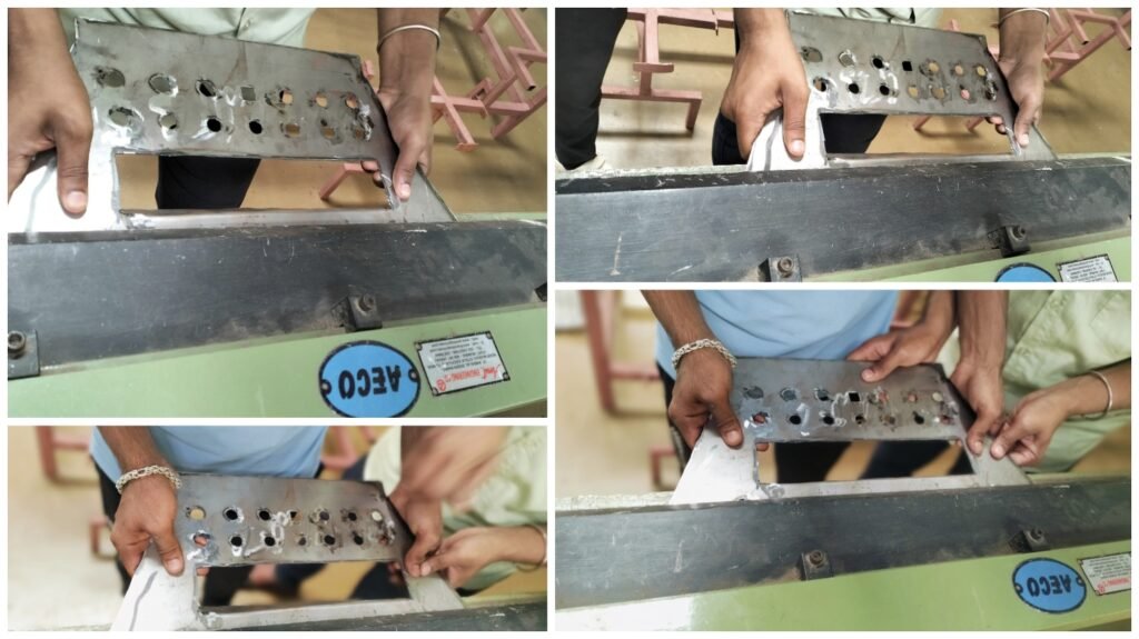
29/09/2024
After vessel stand cutting we did grind but after that the hardest work is sheet bending. Because the sheet was 1.25 mm and if the bending is not done properly, then all the things done so far would have been wasted, so we did the bending properly. But the bending was done as we wanted. And some parts were damaged while bending, then hit it with a hammer.
30/09/2024
Bending of some vessel stands was done yesterday, but the bending of some remaining sheets was completed today. And then Prasad sir was telling about the second assignment.
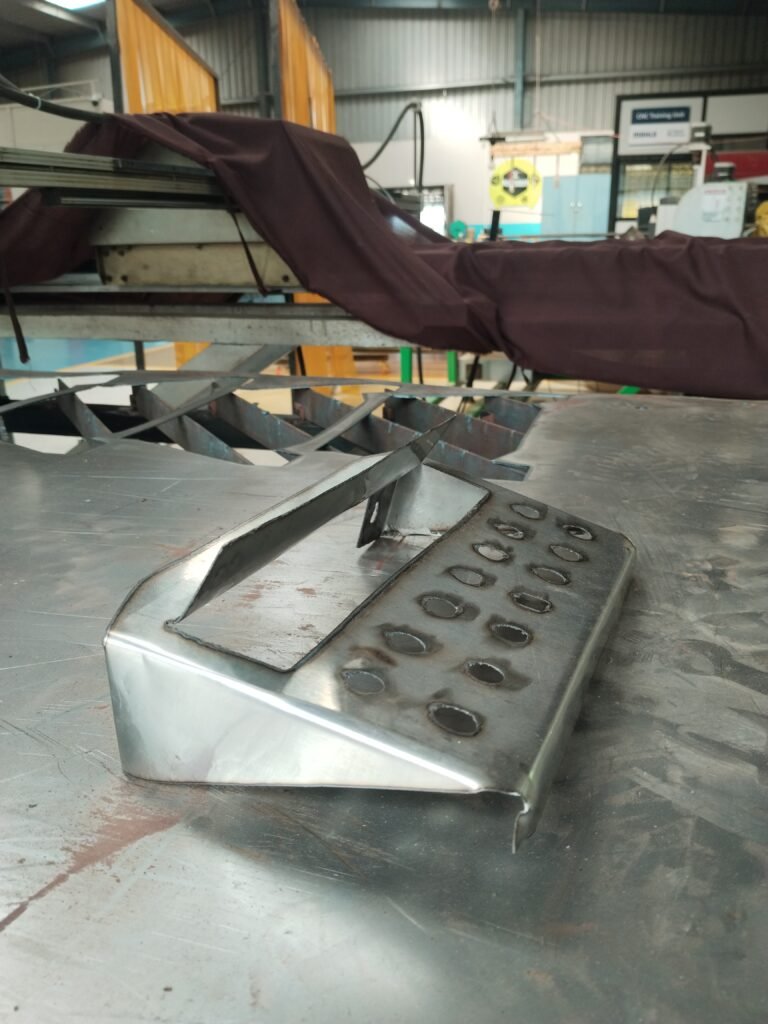
01/10/2024
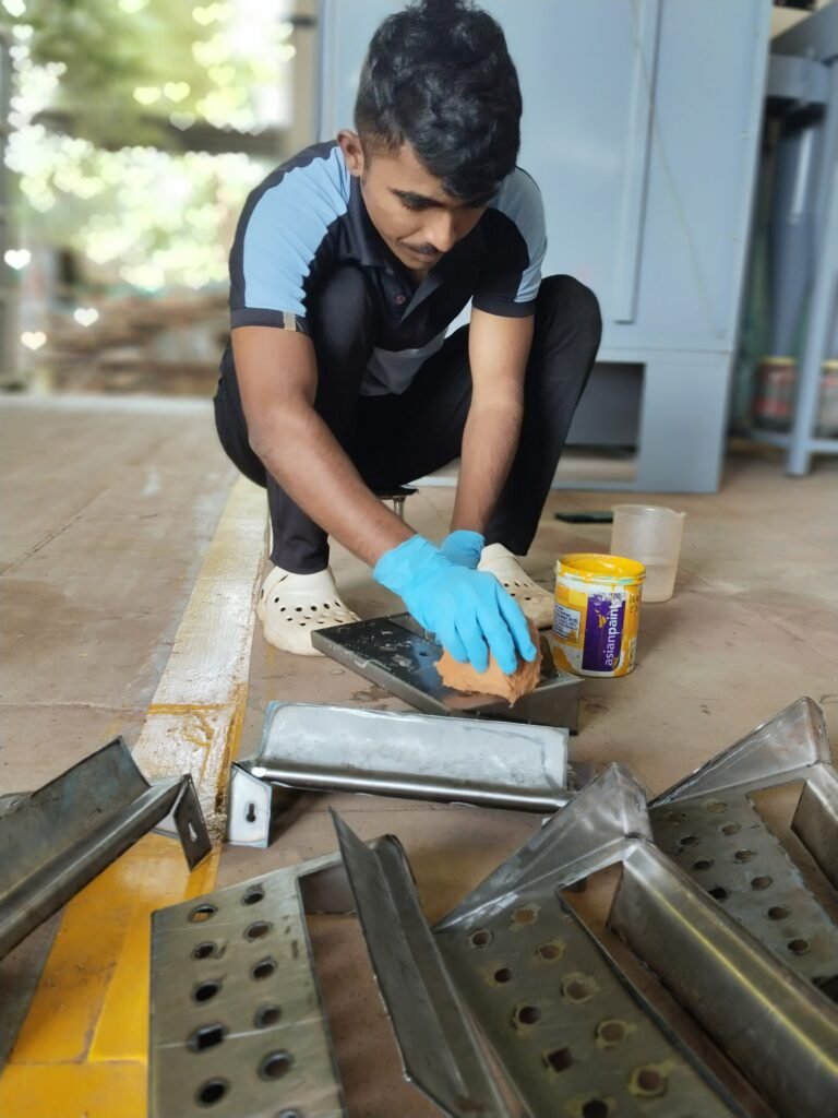
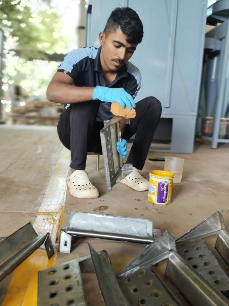
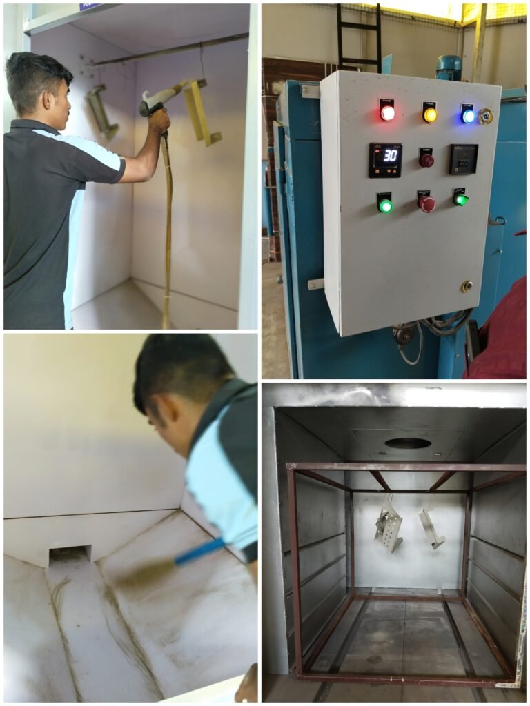
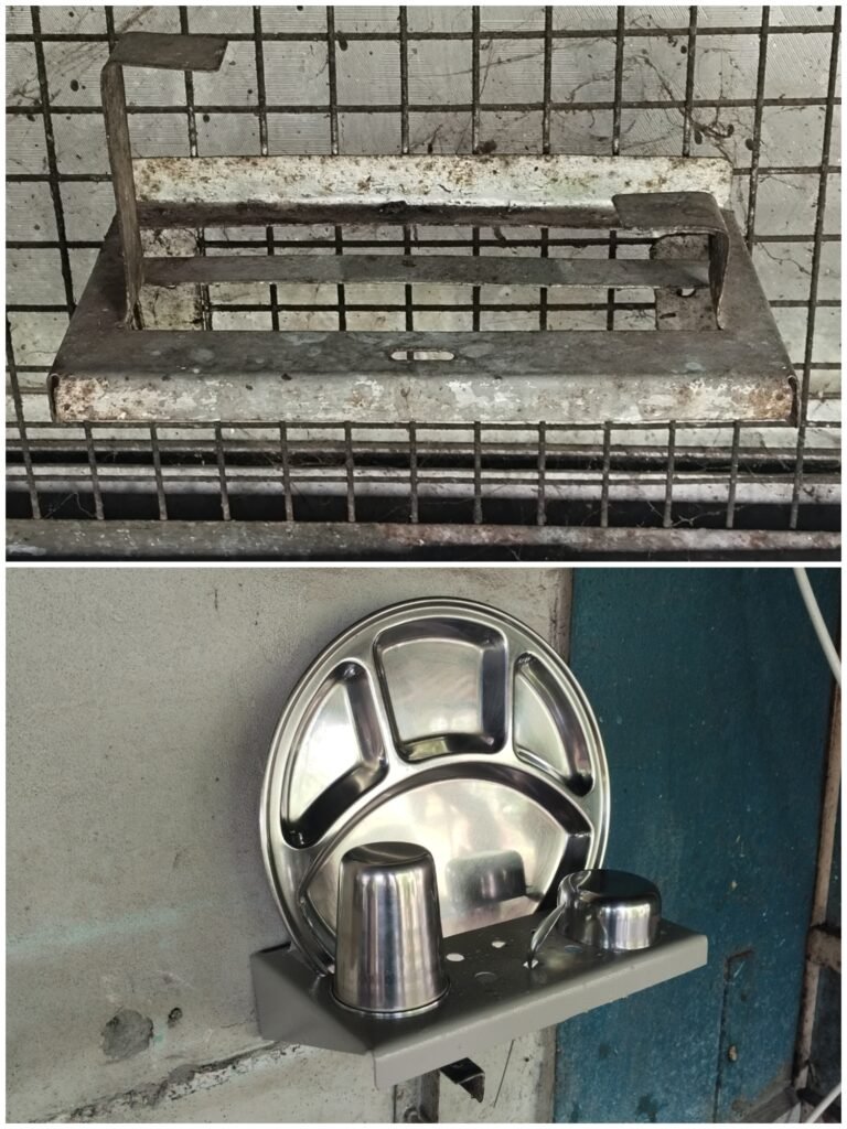
After vessel stand bending he wanted to do powder coating, but before that he wanted to apply 3in1 acid because if the stand is rusted, then the rust comes off. After applying acid, wash it with clean water and keep it to dry for some time. After drying it was powder coated and one by one the powder coated stands were placed in the oven.
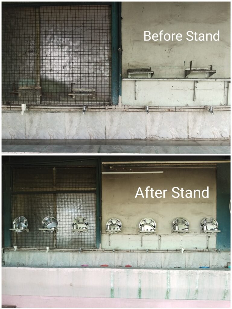
02/10/2024
Took the stand out of the oven and then went to the market to get the screws it needed. There was a lot of problem while installing the stand, because the wall was very old, so the wall was hollow from inside. But that problem was sorted out by adding wood. In this way our first assignment was completed.

