This project aims to design and build a dryer for insect larvae, to support local farmers who use them as a protein-rich feed for their livestock. Drying is a crucial step: it reduces moisture, improves storage life, and makes the larvae easier to transport and handle.
The dryer concept combines two technologies already developed at Vigyan Ashram:
- the grain disinfection unit, which provides a drying chamber with air circulation and vibrating inclined trays to maintain a continuous flow of larvae,
- and the biomass gasifier, which supplies renewable heat using locally available wood residues.
By integrating these two systems, we want to create a low-cost, energy-efficient dryer adapted to the needs of farmers in the region.
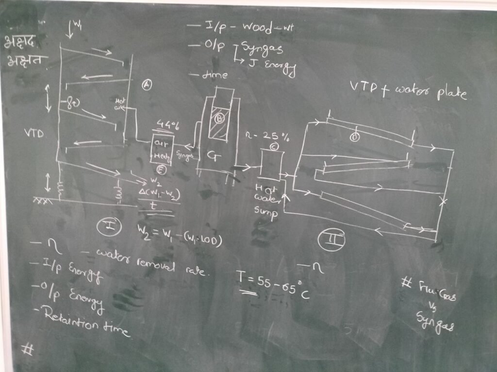
We identified two ways of transferring heat from one to the other : the heat exchanger could either directly heat the air that goes in the drying chamber (I), or alternatively heat water that would circulate in a set of heating plates (II). The first option was chosen for its better overall efficiency.
Dimensioning (27/09/25)
According to this blog, if we use the figures from test 6 (maximum efficiency). The gasifier can produce a total of 256.85MJ in 50 minutes of active burning while consuming 10kg of chopped wood with 8% moisture content and 3kg of charcoal. At first, we assumed that for direct air heating the efficiency would be 44% (this value came from a test with electric heater) so it resulted in a usable 113MJ throughout 50 minutes. This corresponds to an average available thermal power of:
113 MJ / (50 × 60 s) ≈ 37.7 kW.
To estimate how much larvae can be dried in that time and what airflow the dryer needs, I make the following assumptions:
_latent heat of evaporation of water ≈ 2,257 kJ/kg
_the larvae are heated from 25 °C to a drying air temperature of 50 °C
_the wet larvae’s effective specific heat is 3.8 kJ·kg⁻¹·°C⁻¹ (between 4.18 kJ·kg⁻¹·°C⁻¹ for water and 1.5–2.0 kJ·kg⁻¹·°C⁻¹ for the dry matter like proteins, lipids, chitin…)
_incoming ambient air is 25 °C at 50% relative humidity
_the drying air is allowed to reach 100% RH at 50°C before exhaust
Using those numbers, drying 1 kg of input larvae that starts at 50% moisture and finishes at 9.1% (450 g water removed) requires the following energy per kg:
- Latent energy to evaporate 0.45 kg water = 0.45 × 2,257 = 1,015.65 kJ.
- Sensible heating of 1 kg wet larvae (cp = 3.8 kJ·kg⁻¹·°C⁻¹) from 25 °C to 50 °C (ΔT = 25 °C) = 3.8 × 25 = 95 kJ.
- Psychrometrics: at 25 °C saturation ≈ 0.02298 kg H₂O/m³ (incoming at 50% RH = 0.01149 kg/m³); at 50 °C saturation ≈ 0.08288 kg H₂O/m³. So each m³ of 50 °C air can pick up ≈0.08288 − 0.01149 = 0.07139 kg water. That means the volumetric air requirement to remove 0.45 kg water is 0.45 / 0.07139 ≈ 6.303 m³ of drying air per kg of wet larvae.
At an approximate air density of 1.092 kg/m³ at 50 °C, the air mass per kg of larvae is 6.303 × 1.092 ≈ 6.883 kg. Heating that air by 25 °C with cp ≈ 1.005 kJ·kg⁻¹·°C⁻¹ uses about 6.883 × 1.005 × 25 ≈ 172.94 kJ per kg of larvae.
Summing the three terms gives a system energy demand of about 1,015.65 (latent) + 95 (sensible larvae) + 172.94 (air heating) = 1,283.59 kJ per kg (≈1.284 MJ/kg).
With 113 MJ usable over the 50-minute run the system can therefore process:
Processed wet mass ≈ 113,000 / 1,283.59 ≈ 88.03 kg of wet larvae in 50 minutes.
Dried product = 88.03 × 0.55 ≈ 48.42 kg.
Water evaporated ≈ 88.03 × 0.45 ≈ 39.62 kg.
• Volumetric airflow required = 6.303 m³/kg × 88.03 kg / (50*60) s ≈ 0.1850 m³/s ≈ 666 m³/h or 391.99 CFM (Cubic Feet per Minute)
A more streamlined yet still effective version of these estimations was done on this Excel spreadsheet, where we simplified the model by neglecting both the heating of the air and the larvae.
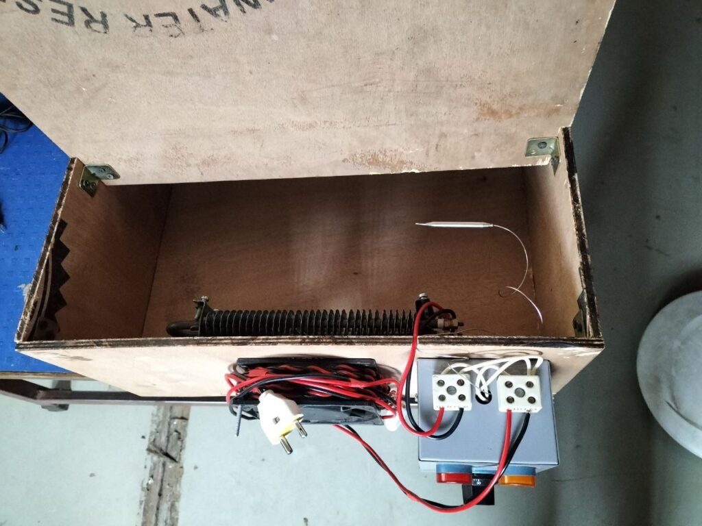
Miniature Experiment (01/10/25)
To validate these calculations, we designed a small-scale version of the dryer to run quick, low-cost experiments before building the full-size unit.
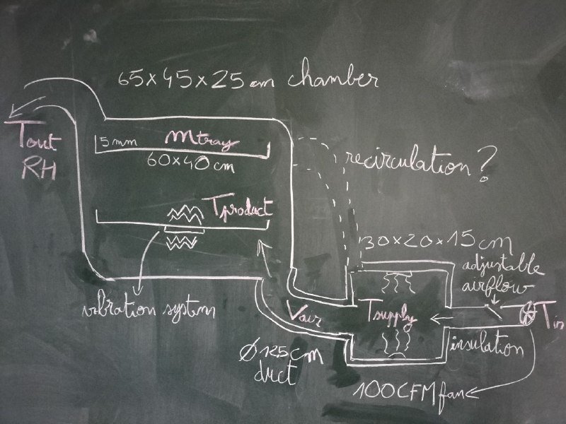
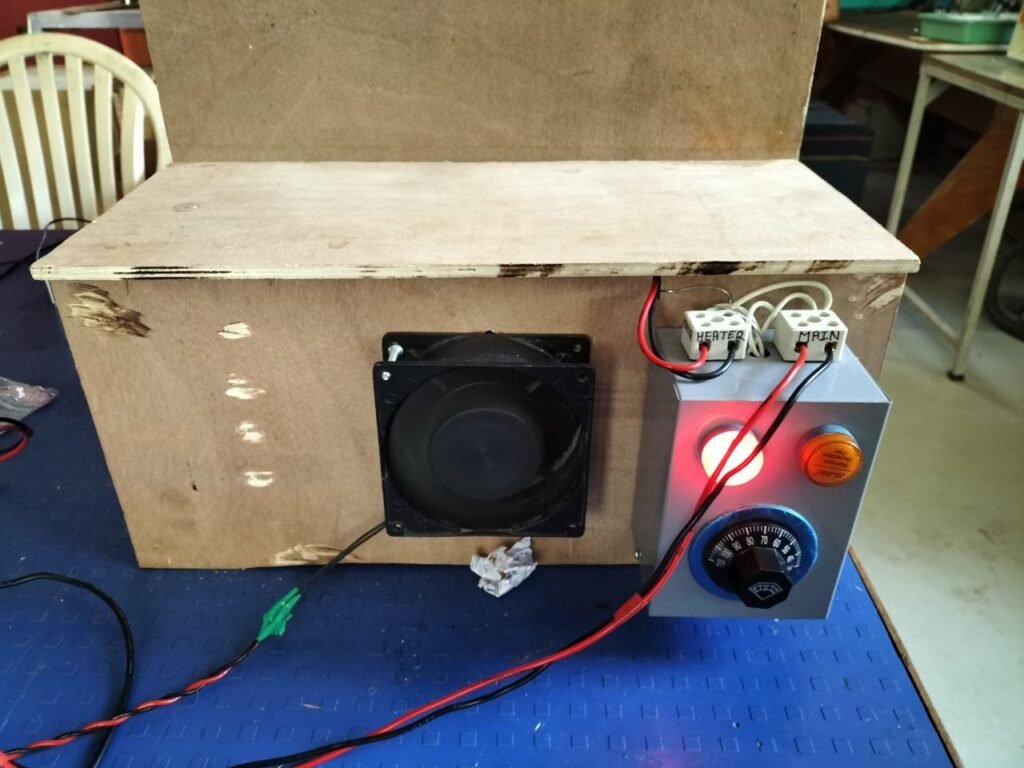
The mini dryer will use:
- Electric heaters (500 W each)
- A 100 CFM fan
- A drying chamber sized for manageable test batches
Airflow should be adjustable through a regulator (using pulse-width modulation to control the fan duty cycle for example) or alternatively with a T-valve on the inlet.
Parameters to monitor:
- Input air temperature
- Heating chamber temperature
- Drying chamber temperature
- Exhaust temperature and relative humidity
- Air velocity in the duct (to compute volumetric flow)
- Mass of larvae before and after drying
In later tests, the setup may also allow partial air recirculation, to study its effect on energy efficiency and drying performance.
Next Steps
These miniature experiments will provide key data on airflow, temperature control, and drying efficiency. With these results, we can confidently dimension and build a larger prototype dryer adapted to the needs of local farmers.
Vibration system (10/10/2025)
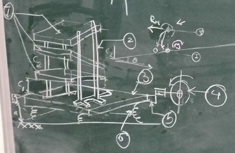
For now we will focus on elements 3, 4, 5, and 6. We model the system as a mass m supported by n vertical linear springs (total stiffness K). The actuator provides a vertical dynamic forcing to produce the vibration amplitude A at drive frequency f.
Static equilibrium
The static deflection δs is how much the springs compress under static load. From force equilibrium: K*δs = m*g
Units: m in kg, g = 9.81 m/s², δs in meters, and K in N/m.
If you use n identical springs, stiffness per spring: kper = K/n
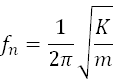
Resonance frequency
The (undamped) natural frequency of the mass–spring system in Hertz (Hz) is
For stability and control (without the need of a PID) we must choose a driving frequency f different from fn.
Dynamic force required for a given amplitude at frequency f
If actuator drives a sinusoidal vertical displacement of amplitude A (m) at frequency f (Hz), the required inertial force amplitude is:

This is the force the actuator must provide (plus losses) as we use peak value for sizing motors.
Actuator options
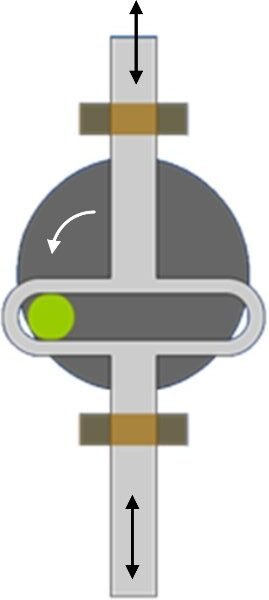
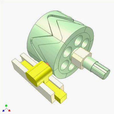
We can use a rotary motor with eccentric mass, scotch-yoke or cam + follower mechanism, or a linear solenoid, either way we need to guide the system on rails.
Option 1)
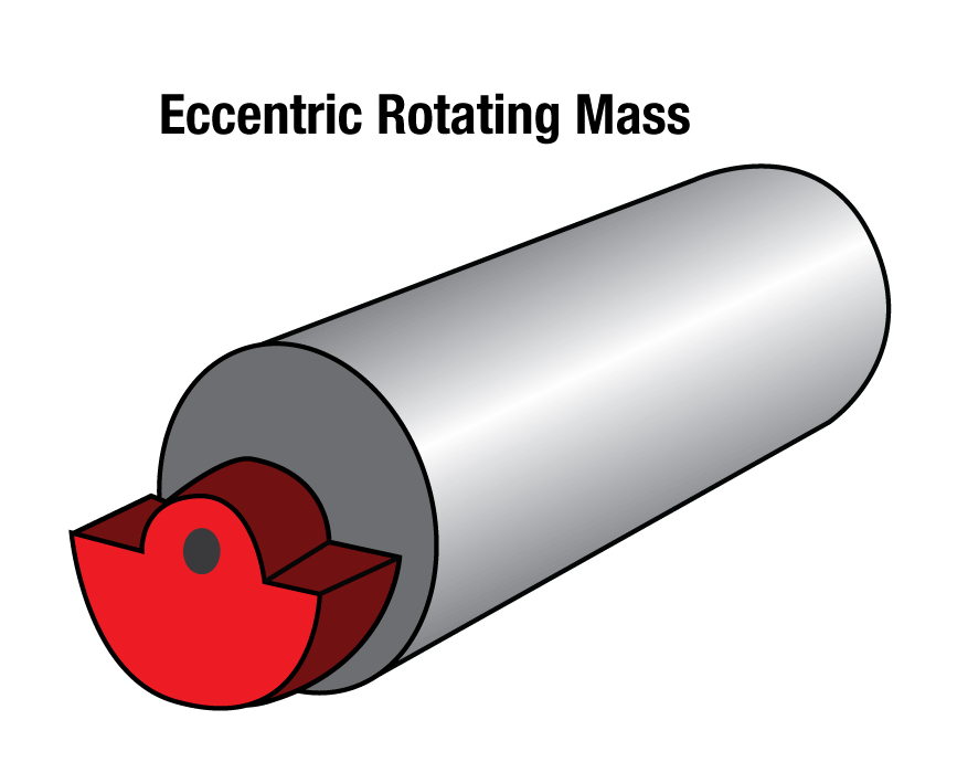
If we use an eccentric mass mecc at radius r rotating at angular speed ω = 2π frpm/60, the peak centrifugal force is:
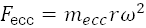
Peak torque required at shaft to generate that force is:

To achieve the target Fpeak on mass m via inertia at frequency f, we must choose mecc and r such that Fecc≈ Fpeak (accounting for mechanical transmission losses).
Option 2)
A scotch-yoke converts rotary motion into near-pure linear motion directly (sinusoidal displacement) so less rotating mass is needed to produce the same linear force compared with a bare eccentric. It also makes it easier to guide the mass on vertical rails and avoid horizontal components of motion.
The scotch-yoke provides better mechanical advantage and can reduce shaft torque (and motor power) for the same vertical output, but it requires a low-friction linear guide and a robust slot that should be designed for easy lubrication and maintenance.
Cam + follower variant
In order to maximize larvae flying height the driving movement should have a maximum of jerk which is why a sinusoid is not optimal. An alternative to the scotch-yoke could be a cam with a follower as this enables to custom the time-position function. For example this barrel cam will force a triangular function which increases the jerk a lot when changing direction leading to higher larvae flight.
Option 3)
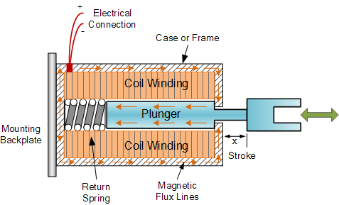
An electromagnetic solenoid pulls or pushes a ferrous plunger when energized. A short, high-energy pulse can produce a rapid vertical impulse which is excellent for making larvae detach and fly. This requires high peak current driver or capacitor discharge circuit for very sharp pulses and it implies thermal limitations.
The cam + follower was identified as the most suitable option but for the miniature experiment a simple eccentric mass rotor will be sufficient and much faster to make.
Numerical estimation for the full-size dryer:
First let’s assume the mass will be 10kg accounting for trays + structure + substrate + follower (assuming option 2 : cam + follower).
For the static deflection 12mm is a reasonable value so we can calculate total stiffness to be K = m g / δs = 10 * 9.81 / 0.012 = 8,183 N/m so if we use 4 springs (one for each corner) then kper = 8,183 / 4 = 2,046 N/m.
And the resonant frequency will be fn = (1/2π) * sqrt(8183/10) ≈ 4.55 Hz.
If we want to drive at f = 10 Hz (fn < 0.5*f to avoid amplification) and amplitude A = 2 mm :
Fpeak = m (2π f)^2 A = 10*(2π*10)^2*0.002 ≈ 78.96 N
So actuator should deliver ~79 N peak vertical force.
Numerical estimation for the miniature experiment:
First let’s assume the mass will be 3kg accounting for trays + structure + substrate + eccentric mass and rotor (assuming option 1).
For the static deflection 5mm is a reasonable value so we can calculate total stiffness to be K = m g / δs = 3 * 9.81 / 0.05 = 5,886 N/m so if we use 4 springs (one for each corner) then kper = 5,886 / 4 = 1,471.5 N/m.
And the resonant frequency will be fn = (1/2π) * sqrt(5,886 /3) ≈ 7.05Hz so we need to drive at more than fmin = 14.1 Hz to avoid amplification.
If we assume the rotor spins 2000rpm equivalent to ~33.3Hz, and we want an amplitude of A = 1 mm :
Fpeak = m (2π f)2 A = 3*(2π*33.3)2*0.001 ≈ 131.33 N
So actuator should deliver ~131 N peak vertical force but in fact we need much less because the rotor will gradually gain speed and once it has reached steady state the motor alternately gives energy to the mass and takes it back such that the average power over a cycle is zero if there are no losses.
Motor dimensioning (15/10/25)
In the case of an eccentric mass rotor, the peak force value (calculated just above) must be equal to the centrifugal force : F = mecc * r * ω2 = Fpeak ≈ 131 N where mecc is the eccentric mass, r is the radius or distance from the center of rotation, and the angular speed ω = 2*π*f = 207.3 rad/s.
So we can choose to use a 150g mass rotating on a 2cm rod (mecc = 0.15kg and r = 0.02m)
The torque T = F * r would then be 2.62 N⋅m and the mechanical power at shaft P = T * ω = 543.13 W. It is important to note that this high wattage is not necessary in the continuous regime, in fact the DC motor that was used is 12V and requires 2A of current so only 24W are required.
Fabrication (until 28/11/2025)
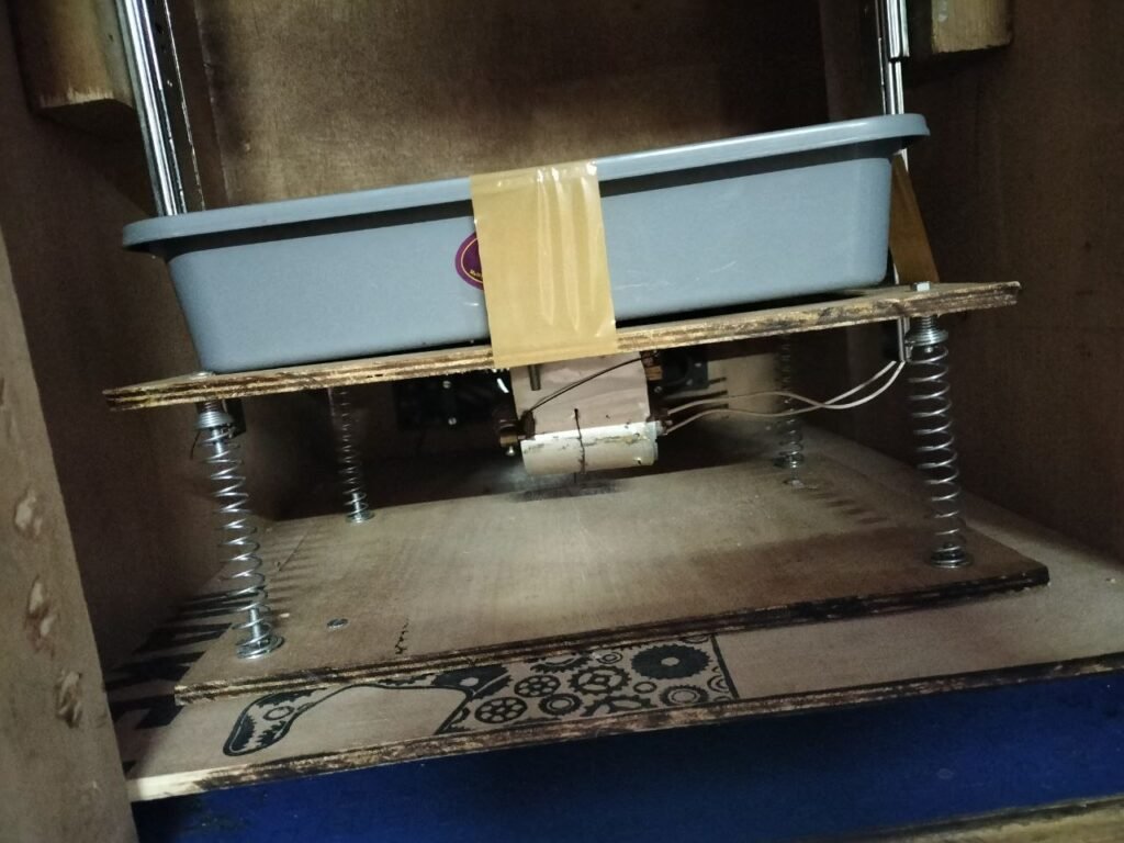
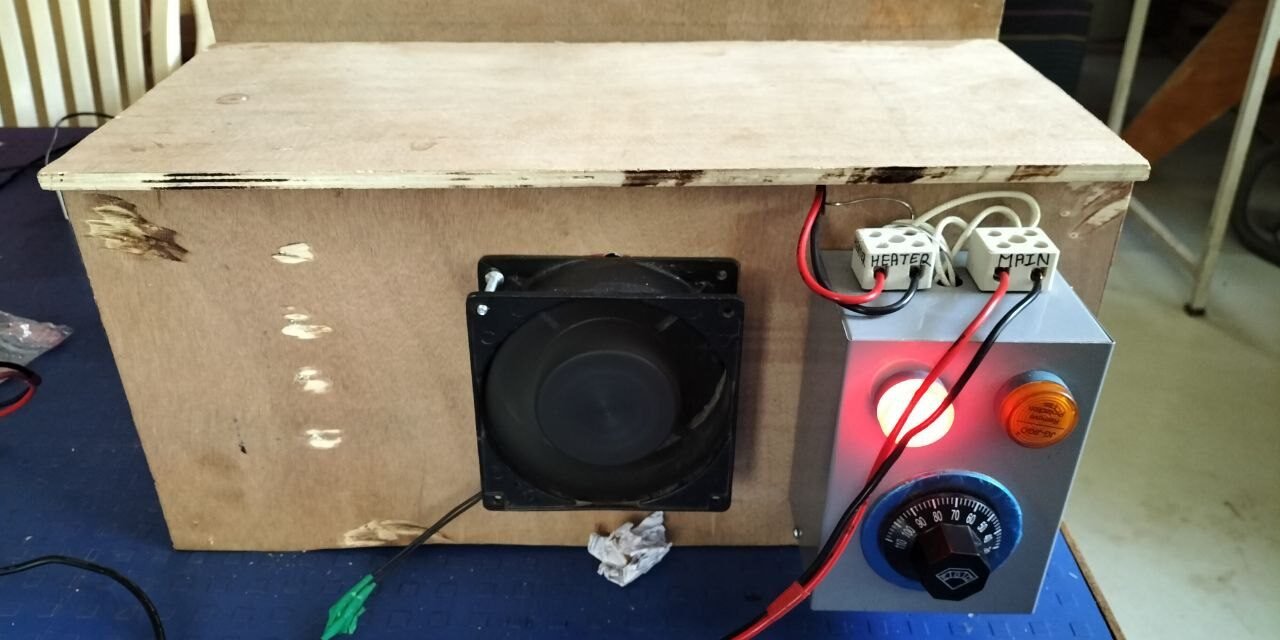
Vertical motion is guided by two rails which ensures that the springs remain strait when more weight is added.
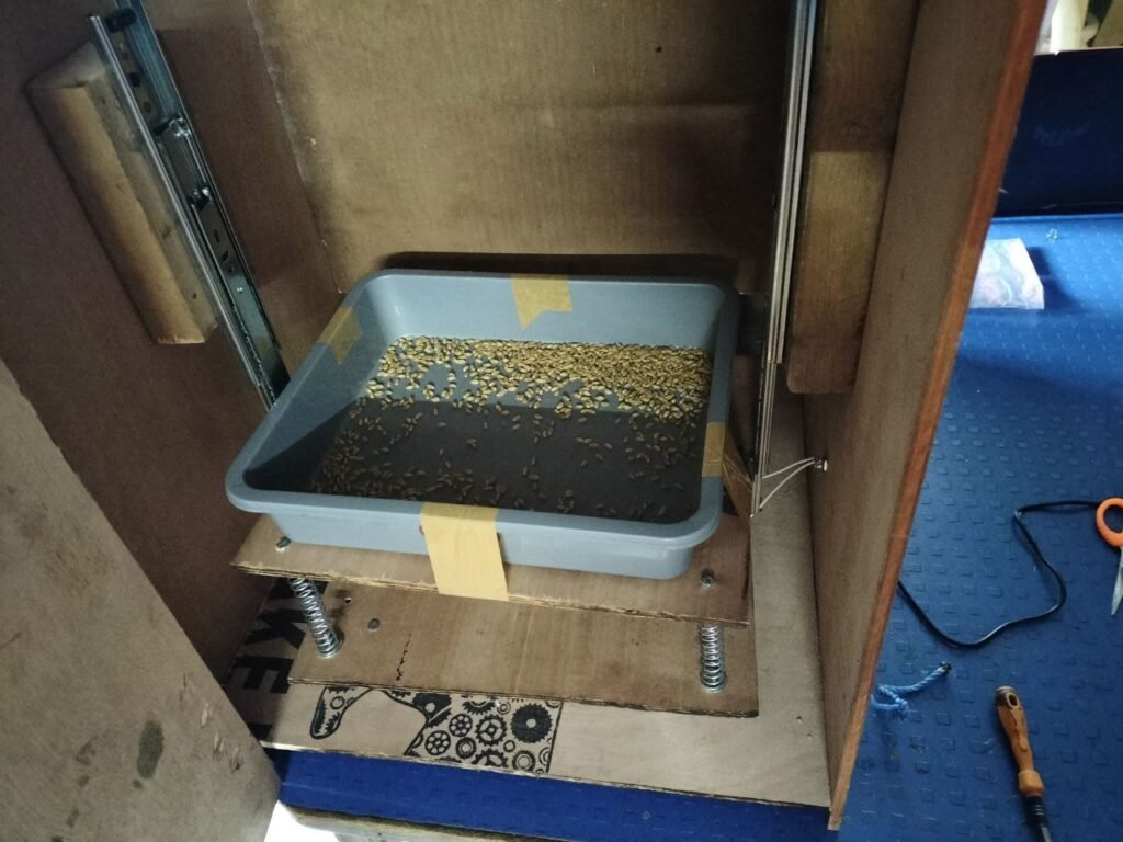
You can see the alimentation port of the rotor as well.
Experimental methodology
The three input parameters are : airflow, temperature, and drying duration. (Flight height can be optimized independently later)
The three output parameters are : relative humidity and temperature at exhaust, and weight loss on the trays.
We can define 3 levels for each input, for example 50, 60 and 70°C for the temperature, that makes a total of 33 = 27 conditions to test at least twice (some trials can be skipped if there is a clear unfavorable trend).
We are looking for the conditions that minimize time and energy consumed to obtain a moisture reduction in larvae from 30% to less than 10%.
Once the optimal conditions have been found, the full-scale dryer with biomass gasifier can be dimensioned accordingly.
