Development of a Connected Nasal Thermometer for a Healthcare Unit
This project was developed for a healthcare unit that approached Suhas sir for the creation of an innovative product. The goal was to design a nasal thermometer equipped with two thermistors (temperature-sensitive resistors) and offer it at an affordable price of 1000 Rs.
First Prototype
The client wanted a compact device capable of connecting to the internet. We chose the ESP32-C3 module, which, although relatively expensive at 500 Rs, is small and has multiple analog pins (ADC), unlike the initially designed Wroom 02D (datasheet)
For the thermistors, our range had to be between 25-50 degrees Celsius (human body temperature), which is a common range for transistors. For this first prototype, we opted for a 10k Ohm thermistor (B25/50 = 3950, tolerance 1%, time constant 10s).
To measure the temperature, we needed a voltage divider, which we achieved using a 10k Ohm resistor.
Electronic Schema

Information about Thermistors:
A thermistor is a resistance thermometer, meaning its resistance depends on temperature. The term is a combination of “thermal” and “resistor.” It is made of metallic oxides, pressed into a bead, disk, or cylindrical shape, and then encapsulated with an impermeable material such as epoxy or glass.
There are two types of thermistors: Negative Temperature Coefficient (NTC) and Positive Temperature Coefficient (PTC). With an NTC thermistor, as the temperature increases, resistance decreases. Conversely, when the temperature decreases, resistance increases. This type of thermistor is most commonly used. (source: Team Wavelength)
Disadvantages and Considerations:
- Slow response to temperature changes (response time to make 66% of change)
- Non linearity
PCB
We created a relatively simple single-sided PCB using the SRM-20 from the fablab (software: https://modsproject.org/).

List of all Components Used
| Nom | Quantité | Prix Unitaire | Lien |
|---|---|---|---|
| ESP32-C3 | 1 | 579 Rs | ESP32-C3 Product Link |
| Thermistor (10k) | 2 | 20 Rs | Thermistor Product Link |
| Resistor (10k) | 2 | Resistor Product Link | |
| Battery | 1 | Battery Product Link | |
| PCB | 1 | PCB | |
| Total |
Arduino Code:
For our Arduino code, we drew inspiration from the following source (Arduino DIY). This code allows us to calculate the temperature value corresponding to the output voltage of the voltage divider for our different thermistor parameters (B, T0) and our circuit (resistor of the voltage divider).
The main modification made was to adapt this code for 2 thermistors (voltage dividers) and to add a line indicating the voltage difference.
Code (GitHub)
Arduino code : thermometer (2 thermistors)
byte NTCPinR = A0;
byte NTCPinL = A1;

#define SERIESRESISTOR 10000
#define NOMINAL_RESISTANCE 10000
#define NOMINAL_TEMPERATURE 25
#define BCOEFFICIENT 3950

void setup()
{
Serial.begin(9600);
}
void loop()
{
float ADCvalueR;
float ResistanceR;
ADCvalueR = analogRead(NTCPinR);
Serial.print("AnalogeR ");
Serial.print(ADCvalueR);
Serial.print(" = ");
//convert value to resistance
ResistanceR = (1023 / ADCvalueR) - 1;
ResistanceR = SERIESRESISTOR / ResistanceR;
Serial.print(ResistanceR);
Serial.println(" Ohm");

float ADCvalueL;
float ResistanceL;
ADCvalueL = analogRead(NTCPinL);
Serial.print("AnalogeL ");
Serial.print(ADCvalueL);
Serial.print(" = ");
//convert value to resistance
ResistanceL = (1023 / ADCvalueL) - 1;
ResistanceL = SERIESRESISTOR / ResistanceL;
Serial.print(ResistanceL);
Serial.println(" Ohm");

float steinhartR;
steinhartR = ResistanceR / NOMINAL_RESISTANCE; // (R/Ro)
steinhartR = log(steinhartR); // ln(R/Ro)
steinhartR /= BCOEFFICIENT; // 1/B * ln(R/Ro)
steinhartR += 1.0 / (NOMINAL_TEMPERATURE + 273.15); // + (1/To)
steinhartR = 1.0 / steinhartR; // Invert
steinhartR -= 273.15; // convert to C

float steinhartL;
steinhartL = ResistanceL / NOMINAL_RESISTANCE; // (R/Ro)
steinhartL = log(steinhartL); // ln(R/Ro)
steinhartL /= BCOEFFICIENT; // 1/B * ln(R/Ro)
steinhartL += 1.0 / (NOMINAL_TEMPERATURE + 273.15); // + (1/To)
steinhartL = 1.0 / steinhartL; // Invert
steinhartL -= 273.15; // convert to C

Serial.print("Temperature right : ");
Serial.print(steinhartR);
Serial.println(" oC");

Serial.print("Temperature left : ");
Serial.print(steinhartL);
Serial.println(" oC");

Serial.print("Difference : ");
Serial.print(steinhartR - steinhartL);
Serial.println(" oC");


delay(1000);
}
Development of UI – Test
For the UI, we drew inspiration from the work done on various dataloggers, making simple adjustments to the displayed variables and the layout of different elements. Two thermometers indicate the temperatures of the right and left thermistors, while a gauge below displays the temperature difference.
Similar to dataloggers, it’s also possible to display graphs showing the data’s evolution and provide the option to download the data.
UI Overview:

- Video demonstration
Microcontroller Code adapt to UI and Seed – XIAOC3:
To create the UI, we needed to enhance the previously proposed code to tailor it to our specific requirements. Two key tasks were required: establishing the connection to Firebase and WiFi, as done in previous datalogger codes, and adapting the code for the SEED-XIAO C3 microcontroller.
For the first part, refer to the code (GIT) and the earlier work on the datalogger.
Adapting the code for the microcontroller is a bit more technical. Unlike Arduino, the ADC of the C3’s analog pins only extends up to 2.8V (note that the datasheet mentions 2.5V, but this contradicts experiments conducted with a laboratory voltage source). Adjustments to the voltage divider range are necessary to align it with the new scale, considering the max ADC value is 2.8V, not the 3.3V of the power supply. Fortunately, within our 5-70 degree range, issues should not arise with our setup.
It’s worth noting that the previously presented diagram is dysfunctional. The power supply should be 3.3V, not Vin (5V), and the voltage divider setup is reversed. While not a problem, this needs to be considered in the code, as demonstrated below.
Another problem appears from quick variation from one value to another with add an average of the 10 previous value to smooth the curve
Code Aruino:
XIAO-C3 code : thermometer (2 thermistors) voltage divider inversed
byte NTCPinR = A0;
byte NTCPinL = A1;
//byte NTCPinR = 1;
//byte NTCPinL = 2;
int ADC = 4095 * 3.3/2.84 ; //1023 arduino 4095 esp32 c3
//int ADC = 4095;
#define SERIESRESISTOR 10000
#define NOMINAL_RESISTANCE 10000
#define NOMINAL_TEMPERATURE 25
#define BCOEFFICIENT 3950

void setup()
{
Serial.begin(9600);
pinMode(A0,INPUT);
pinMode(A1,INPUT);
}
void loop()
{
float steinhartRmean = 0;
float steinhartLmean =0;
int i =0;
  while (i < 10){
    float ADCvalueR;
    float ResistanceR;
    ADCvalueR = analogRead(NTCPinR);
    // Serial.print("AnalogeR ");
    // Serial.print(ADCvalueR);
    // Serial.print(" = ");
    //convert value to resistance
    ResistanceR = (ADC / (ADC-ADCvalueR)) - 1;
    //// new line
    //Rcable =
    //ResistanceR = ResistanceR - Rcable;
    //
    //// end new line
    ResistanceR = SERIESRESISTOR / ResistanceR;
    // Serial.print(ResistanceR);
    // Serial.println(" Ohm");

    float ADCvalueL;
    float ResistanceL;
    ADCvalueL = analogRead(NTCPinL);
    // Serial.print("AnalogeL ");
    // Serial.print(ADCvalueL);
    // Serial.print(" = ");
    //convert value to resistance
    ResistanceL = (ADC / (ADC-ADCvalueL)) - 1;
    ResistanceL = SERIESRESISTOR / ResistanceL;
    // Serial.print(ResistanceL);
    // Serial.println(" Ohm");

    float steinhartR;
    steinhartR = ResistanceR / NOMINAL_RESISTANCE; // (R/Ro)
    steinhartR = log(steinhartR); // ln(R/Ro)
    steinhartR /= BCOEFFICIENT; // 1/B * ln(R/Ro)
    steinhartR += 1.0 / (NOMINAL_TEMPERATURE + 273.15); // + (1/To)
    steinhartR = 1.0 / steinhartR; // Invert
    steinhartR -= 273.15; // convert to C

    float steinhartL;
    steinhartL = ResistanceL / NOMINAL_RESISTANCE; // (R/Ro)
    steinhartL = log(steinhartL); // ln(R/Ro)
    steinhartL /= BCOEFFICIENT; // 1/B * ln(R/Ro)
    steinhartL += 1.0 / (NOMINAL_TEMPERATURE + 273.15); // + (1/To)
    steinhartL = 1.0 / steinhartL; // Invert
    steinhartL -= 273.15; // convert to C

    i++;
    steinhartRmean = steinhartR+steinhartRmean;
    steinhartLmean = steinhartL+steinhartLmean;

    delay(100);
}
steinhartRmean = steinhartRmean /10;
steinhartLmean = steinhartLmean /10;

Serial.print("Temperature right : ");
Serial.print(steinhartRmean);
Serial.println(" oC");

Serial.print("Temperature left : ");
Serial.print(steinhartLmean);
Serial.println(" oC");

Serial.print("Difference : ");
Serial.print(steinhartRmean - steinhartLmean);
Serial.println(" oC");


}
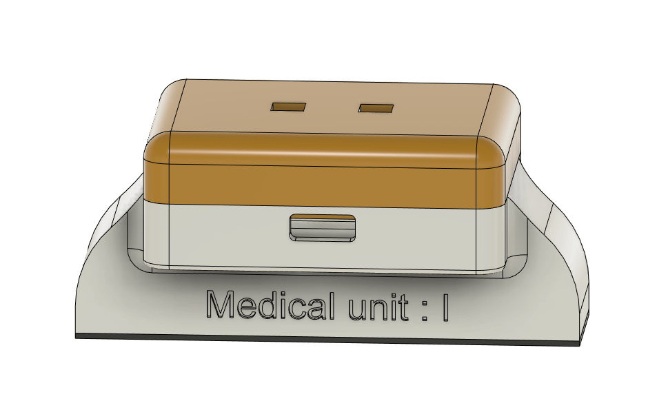
Casing Design:
The final part of the project involves creating a casing to accommodate the PCB and battery, providing access for the USB-C cable, and allowing for the protrusion of the two sensors.
1st prototype


Video
Version 2
This second version addresses the issue of the first version by adding an LED and making it easier to access the thermistors. Circuit problems are also resolved by replacing the 5V pin with the 3.3V. Finally, the code is adapted to work with Firebase (database) and the UI to create a functional product.
Arduino code with link to firebase :
XIAO-C3 code : thermometer (2 thermistors) voltage divider inversed
//---------------
int ADC = 4095 * 3.3/2.84 ; //1023 arduino 4095 esp32 c3
//int ADC = 4095;
#define SERIESRESISTOR 10000
#define NOMINAL_RESISTANCE 10000
#define NOMINAL_TEMPERATURE 25
#define BCOEFFICIENT 3950

#define WIFI_WORKSHOP
// #define ESP32
#include
#include

#include
#include "time.h"


//include the following for the Firebase library to work.
// Provide the token generation process info.
#include "addons/TokenHelper.h"
// Provide the RTDB payload printing info and other helper functions.
#include "addons/RTDBHelper.h"

// Insert your network credentials and make sure the define at the beginning of the document is correct
#if defined(WIFI_WORKSHOP)
  #define WIFI_SSID "Workshop"
  #define WIFI_PASSWORD "@@vigyan@@"

  //#define WIFI_NAME "WS"
#endif

// Insert Firebase project API Key
#define API_KEY "AIzaSyDR0TDLqgKFygypBmFsdJ-m5_80K4-mXlY" //"va-black-soldier-flies" firebase project

// Insert Authorized Email and Corresponding Password
#define USER_EMAIL "medicalteam1@email.com" //you can also choose: va_esp32_test@gmail.com
#define USER_PASSWORD "123456789"

// Insert RTDB URLefine the RTDB URL
#define DATABASE_URL "https://medical-application-68d66-default-rtdb.asia-southeast1.firebasedatabase.app/"

// Define Firebase objects
FirebaseData fbdo;
FirebaseAuth auth;
FirebaseConfig config;

// Variable to save USER UID
String uid;

int hours;
int minutes;

// Database main path (to be updated in setup with the user UID)
String databasePath;

// Database child nodes
String tempLpath = "/templeft";
String tempRpath = "/tempright";
String tempdiff = "/difference";

String timePath = "/timestamp";

// Parent Node (to be updated in every loop)
String parentPath;

int timestamp;
FirebaseJson json;

const char* ntpServer = "pool.ntp.org";

float steinhartRmean = 0;
float steinhartLmean =0;
float difference =0;

// Timer variables (send new readings every three minutes)
unsigned long sendDataPrevMillis = 0;
//unsigned long timerDelay = 15*60*1000; //30 minute delay, 1 sec = 1000 for timerDelay // change for testing
unsigned long timerDelay = 10*1000; //10s delay change for testing


//variables for actuators
unsigned long delayTime;


// Initialize WiFi
void initWiFi() {
  Serial.print("Connecting to ");
  Serial.println(WIFI_SSID);
  WiFi.begin(WIFI_SSID, WIFI_PASSWORD);
  Serial.print("Connecting to WiFi ..");
  while (WiFi.status() != WL_CONNECTED) {
    Serial.print('.');
    delay(1000);
  }
  Serial.print("\nConnected to WiFi!\n");
  Serial.println("IP address: ");
  Serial.println(WiFi.localIP());
  Serial.println();
}

// Function that gets current epoch time
unsigned long getTime()
{
  time_t now;
  struct tm timeinfo;
  //5h30 dECALAGE
  if (!getLocalTime(&timeinfo)) {
    //Serial.println("Failed to obtain time");
    return(0);
  }
  hours = timeinfo.tm_hour;
  minutes = timeinfo.tm_min;
  time(&now);
  return now;
}
void control()
  {
    int i =0;
    while (i  timerDelay || sendDataPrevMillis == 0)){
    sendDataPrevMillis = millis();
//////
  Serial.print("\nTemperature Left= ");
  Serial.print(steinhartRmean);
  Serial.print("°C");
  Serial.print("\nTemperature Left= ");
  Serial.print(steinhartLmean);
  Serial.print("°C");
  Serial.print("\ndifference= ");
  difference = steinhartLmean - steinhartRmean;
  Serial.print(difference);
  Serial.print("°C");
///////

  timestamp = getTime();
  Serial.print ("current time: ");
  Serial.println (timestamp);
  Serial.println (hours);Serial.println (minutes);

    parentPath= databasePath + "/" + String(timestamp);

    json.set(tempLpath.c_str(), String(steinhartLmean));
    json.set(tempRpath.c_str(), String(steinhartRmean));
    json.set(tempdiff.c_str(), String(difference));

    json.set(timePath, String(timestamp));

    //We can call that instruction inside a Serial.printf() command to print the results in the Serial Monitor at the same time the command runs.
    Serial.printf("Set json... %s\n", Firebase.RTDB.setJSON(&fbdo, parentPath.c_str(), &json) ? "ok" : fbdo.errorReason().c_str());
  }
}
UI Code
Acces link : LINK_TO_UI_CODE
Final electrical diagram

Final PCB

List of all Components Used for v2
| Nom | Quantity | Lien |
|---|---|---|
| ESP32-C3 | 1 | ESP32-C3 Product Link |
| Thermistor (10k) | 2 | Thermistor Product Link |
| Resistor (10k) | 2 | |
| Battery | 1 | Battery Product Link |
| PCB | 1 | |
| Led | 1 | |
| Resistor (led) | 1 |


