Existing Challenge
Measuring water level, monitoring and maintaining it is complicated task, many times we don’t have water remaining in overhead tank when required, and on other hand sometimes water overflows due to not monitoring the water level.
Implementing a automated system with water level sensor will helpful to log the water level data and monitor consumption as well as time of filling the overhead tank.
Currently challenge is limitation of water level sensor to measure water level up to certain limit, and the available depth sensor is costly.
Solution
Designing a sensor that will be able to detect depth with accuracy and cost effectiveness.
I will be working on two types of sensors for this project.
1. A rack and pinion mechanism Connected with potentiometer.
2. a pressure sensor to detect hydrostatic pressure and we will convert it to related water level.
Rack and pinion mechanism
Working principle
Rack and pinion mechanism converts linear motion into angular or vice versa, so by using this motion we are able to detect linear displacement in angular form with the use of potentiometer.
Bill of material
- Acrylic sheet 4mm.
- Gearbox with 100:1 reduction.(Currently used gearbox which is existing with geared motor)
- Potentiometer.
- Microcontroller.(in testing phase)
- Machine Screw M4*20mm*6 Nos
- Grub screw M3*8mm*1 No
- Brass stud M3*20*1 No
- Machine screw M3*25*1 No
- Float ball
Procedure
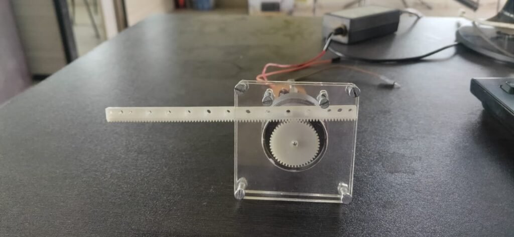
- Rack will be connected to one end with float valve and engaged with pinion.
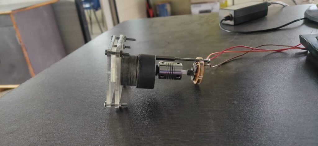
- Gearbox will be directly coupled with pinion so we will get reduced motion. (i.e. 0 to 180 degrees with actual 0-36000 degrees as pinion will have to make 36000 turns to rotate potentiometer by 360 degrees.
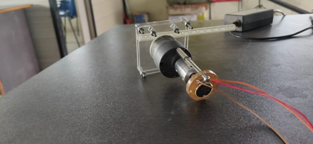
- potentiometer will be coupled with output shaft of gearbox.
- Potentiometer is supported by acrylic sheet which is connected to motor body for support.
First prototype for rack and pinion sensor
In this category first prototype is ready for testing.


