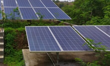
- Solar charging device: Solar charging device is composed of a solar panel, regulated circuit ,battery. Solar chargers can charge from solar energy to supply electricity to devices or batteries (Li-ion, lead acid, Ni-Cd battery).Most of them are generally portable and can supply up to 48 volts and 4000-ampere hours.Public solar chargers are permanently installed in public places, such as parks, squares and streets, which anyone can use for free.
- Objective :
- To use solar charging device as an important alternative to electricity in areas where electricity is difficult to reach especially in rural and tribal areas.
- To increase use of renewable energy because it’s pollution free energy.
- To save electricity.
- Project description :
While traveling or regularly performing activities such as camping,trekking then we need a portable source of energy. Most of the village where electricity has reached, load shedding is more than 7-8 hours/day. In such a situation, we can use this device to charge cell phones and other small electronic devices. Solar energy is the best alternative to electricity. So while traveling we use solar charging device.
- Required Other material and specifications:
| Sr. No. | Material description | Specification | Quantity |
| 1 | Solar panel | 10 watt | 1 |
| 2 | Dc-Dc boost converter module | Dual micro USB 3.7 V to 5 V, 2 A power bank charging module | 1 |
| 3 | Batteries | 3.7V, 2600mAh | 4 |
| 4 | Box | 1 |
Other material: Connecting wires, multi-meter, soldering gun, insulation tape, glue gun etc.
- Steps: i)connection of batteries
Series connection: For this connection all batteries are connected positive to negative end to end. The voltage of each battery is added but the capacity remains the same.
Parallel connection: For this connection all positive and negative terminals of batteries together.The of each battery is the same but capacity of each battery is added.
ii) Batteries : For the circuit we required 5V,2A DC supply. So we connect 4 batteries of 3.7V,2600mAh is in parallel.
iii) Assemble the system and put it all together: As per connection diagram, Connect positive and negative terminal of battery connected to the Dc-Dc boost converter module. Total circuit fixed in the box. Take two input terminals from the Dc-Dc boost converter module.
Input terminals are connected to positive and negative terminals of the solar panel to the Dc-Dc boost converter module.
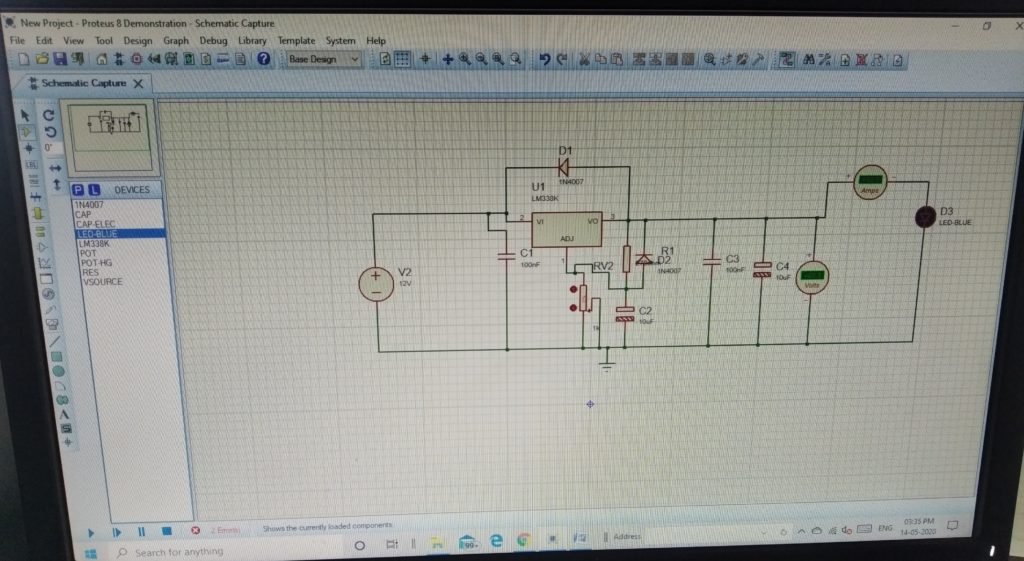
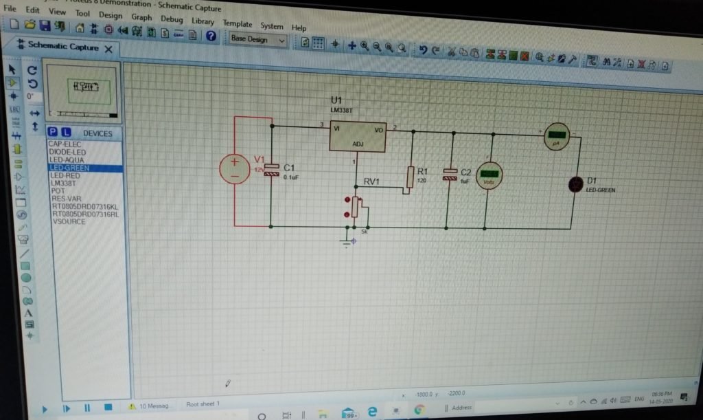
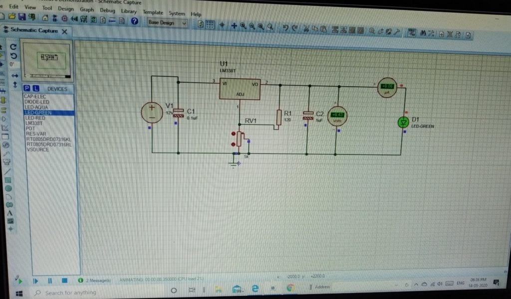
iv) But this Dc-Dc boost converter module is not working due to internal damage, so now I work on 5 V, 2 A dc regulated power supply circuit.
- Bill of material
| Sr. no. | Material | Cost of material |
| 1 | Solar panel (10watt) | Rs.600 |
| 2 | Dc-Dc boost converter module | Rs. 940 |
| 3 | Batteries | Rs. 400 |
| 4 | Box | Rs. 300 |
- Proteus Software: The Proteus Design Suite is a proprietary software tool suite used primarily for electronic design automation. The software is used mainly by electronic design engineers and technicians to create schematics and electronic prints for manufacturing printed circuit boards. The PCB Layout module is automatically given connectivity information in the form of a netlist from the schematic capture module. It applies this information, together with the user specified design rules and various design automation tools, to assist with error free board design. PCB’s of up to 16 copper layers can be produced with design size limited by product configuration.
- 5 V, 2 A regulated power supply circuit diagram in Proteus
