Introduction :
An incinerator is generally defined as any furnace used in the process of burning solid waste for the purpose of reducing the volume of the waste by removing combustible matter. Emissions of concern include particulates and potentially harmful pollutants depending on what is being burned.
Drawbacks in Version 1 :
- Ash Tray
- Body Temperature
- Heat Flow
- Smoke
Discussion 1 :
Defining of Problems –

Problems Defined :
- Ash Tray – Uneven falling of Ash on floor and blockage of burner nozzles due to ash.
- Body Surface Heating – Heating of Body Surface during operation makes it difficult for handling.
- Heating Chamber Airflow – Not proper airflow in heating chamber.
Date: 19/10/2021 (Tuesday)
Discussion 2 :
Ideation – (Ash Tray & Design of Burner)

Brainstorming Points :
- Round Burner with nozzles holes on side.
- Flat Burner mounted on Sides of Inner Chamber.
- Pipe Burner with linear holes.
- Circular pipe burner with holes pointing towards pads.
- Internal Combustion chamber with gas and air mixture and spark for ignition of pads.
Date: 25/10/2021 (Monday)
Discussion 3 :
Ideate – (Burner Design)

Brainstorming Points :
- Shortlisting of Pipe Burner with nozzles at lateral position.
- Understanding concept for design of manifold for burner.
- Checking the availability of Burner in market.
Date: 17/11/2021 (Wednesday)
Availability of Burner in Market : (Not Available in India)

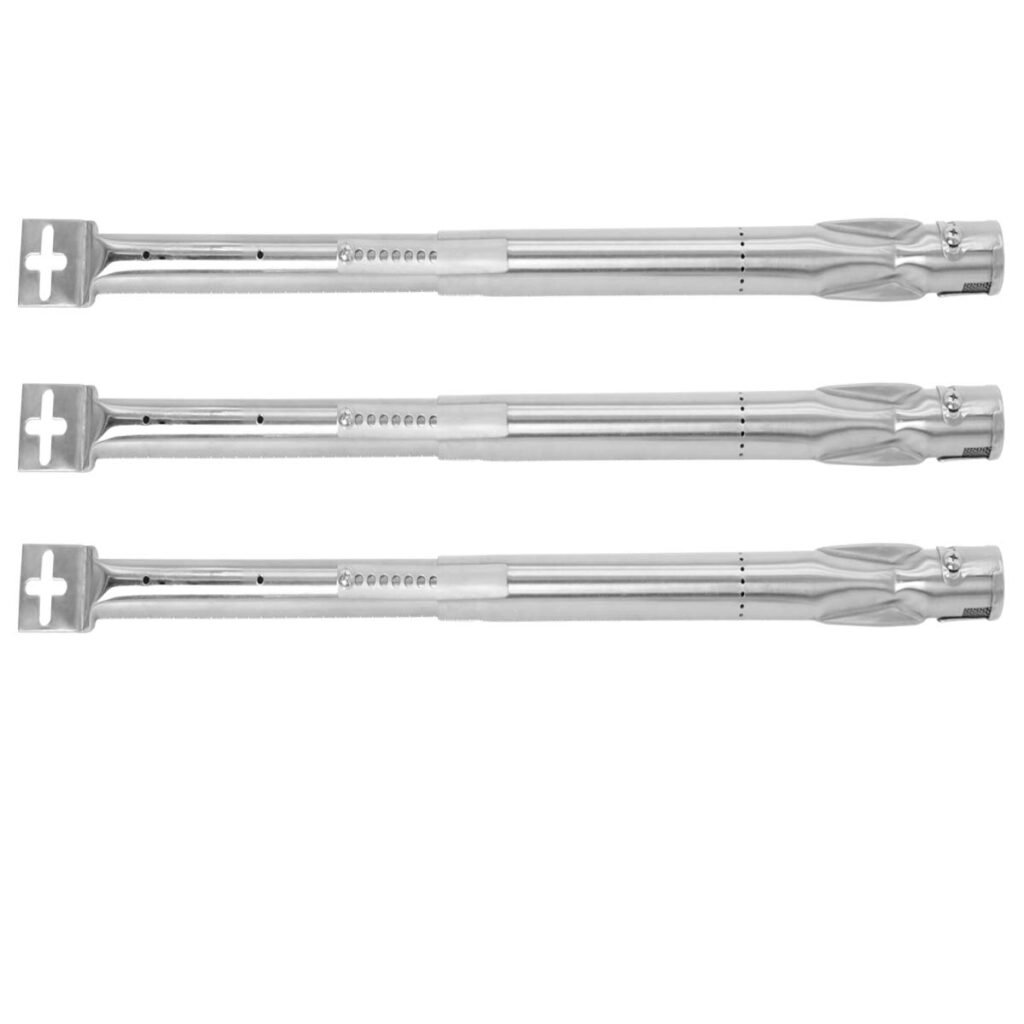
BBQ Stainless Steel Adjustable Grill Pipe Burner Tube for Most Gas Grill
Extendable Length from 14″ to 19″, 3pcs
Cost: ₹2293
- Due to availability and cost of available burner in market, I decided to design and fabricate the burner on my own…
Design and Fabrication of Burner :
- Trial 1 :
Feedback Trial 1:
- Initial nozzles of burner were not working due to pressure drop area.
- Burner was making backfire due to low velocity of mixture and high amount of primary air.
- Trial 2: (Actual trial on pads)
Discussion 4 :
Ideate – Burner Design

Brainstorming Points :
- Understanding concepts for burner design.
- Understanding Bernouli’s principle and ventury effect for ventury design.
- Defining proper dimensions of air slit. (Air Slit : Gaps on mixing pipe for primary air intake)
- Setting up second burner at top of inner chamber for complete combustion of pyrolitic gases.
Date: 22/11/2021 (Monday)
Concept of Burner:
How does combustion occur?
The release of the potential energy of fuel by combustion with air requires several stages, namely.
• Mixing of air and fuel
• Ignition of the mixture
• Chemical reaction
• Disposal of products of combustion from the reaction site so that fresh reactants are available.
Except mixing of air and fuel, all other stages are extremely fast such that it is said that if fuel and air are mixed, fuel is burnt. Accordingly mixing is the slowest step in the process of combustion. This can be understood by considering that each mole of carbon theoretically requires 1 mole of oxygen for complete combustion. But 1 mole of oxygen is obtained from 4.76 moles of air. That means 3.76 moles of nitrogen are present with 1 mole of oxygen. Nitrogen is inert and does not take part in combustion therefore mixing of air + fuel is important.
What is a burner?
A burner is a mechanical device that-
• supplies required amount of fuel and air
• creates conditions for rapid mixing of fuel and air
• produces a flame which transfers thermal energy to furnace and charge
Mixing of air and gaseous fuel:
In the diffusion burner, air and gaseous fuel are supplied separately in the furnace. In most combustion systems mass of air is at least 8 to 9 times that fuel. When air and fuel pass through the burner, the momentum flux of air is several times greater than fuel. Some fraction of total air is mixed with the fuel and this air is known as primary air. The rest amount of the air, known as secondary air is supplied in the furnace through appropriate locations. Mixing and combustion take place simultaneously.
When a mixture of air and gaseous fuel passes through the burner, a free jet is produced downstream the burner. If the air-fuel mixture is discharged in the furnace then a confined jet is produced because of the furnace walls. The difference between the free jet and confined jet is that in the former the amount of surroundings is unlimited whereas, in the latter, the amount is limited. Mixing secondary air in the jet is important for complete and efficient combustion. In the absence of mixing the chances of CO formation can not be ruled out.
Characteristic features of jet:
A jet is produced when a fluid is discharged through the nozzle. In the jet, the velocity of the fluid is accelerated. Free jet is produced when the fluid is discharged in the surrounding with no confinement. A jet is said to be confined when the fluid is discharged in the container. The characteristic feature of the jet (whether free or confined) is that it spreads due to the difference in the density of the jet and the surrounding. A hot jet in the cold surrounding spreads faster than a cold jet in the same surrounding.
The spreading of the jet is due to the entrainment of the surrounding. Due to the entrainment of the surrounding, the axial velocity of the jet decreases. For any downstream axial distance, the maximum velocity is at the center and minimum at the periphery such that a parabolic profile is developed as shown in figure

Concept of Venturi:
A gas or fluid passes through a pipe that narrows or widens, the velocity and pressure of the gas or fluid vary. As the pipe narrows, the gas flows more rapidly. What sounds like a surprise but holds true, is that when the fluid or gas flows faster through the narrow sections, the pressure actually decreases rather than increases. The venturi tube is a large diameter tube, gradually feeding into a smaller tube and then gradually becoming a larger tube.
Source https://www.physicsforums.com/threads/gas-burner-venturi-effect.526432/
Setting up second burner at top of inner chamber for complete combustion of pyrolitic gases :
Trial 1: Results
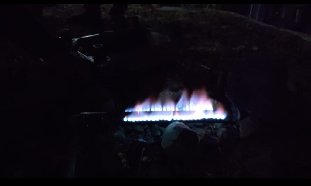
- It was seen that the flame of flare burner was yellowish orange in colour as shown in video.
- The amount of smoke coming out of chamber was reduced
- The unburnt pyrolytic gases were combusting completely which results in less amount of smoke.
Feedback:
- When flame is low the cloud of smoke gets formed, this results in more amount of smoke coming out from chamber.
Discussion 5:
Brainstorming Points:
- Accumulating the smoke by providing baffels in the chamber will lead the smoke to accumulate inside the chamber.
- The unburnt pyrolytic gases can be used for self-burning of pads.
- The accumulation of gases will lead the complete combustion of pyrolytic gases with flare.
Trial 2: Results
- The amount of the gases coming out of the chamber gets reduced to 5% of total.
- The flame of flare burner ultimately incresed.
- The flame of self-burning pads increased.
- It was seen that the pyrolytic gases acts as a fuel for self-burning of pads.
Conclusion:
- The problem of ash traping inside the nozzle gets solved with the help of pipe burner with nozzles at lateral side.
- The ash gets accumulated at the bottom of burner without trapping inside the burner.
- The ash can be evenly collected by mounting the ash tray below the burner.
- The smoke coming out of chamber gets ultimately reduced due to implementation of flare burner at the top of chamber.
- The unburnt pyrolytic gases acts as a fuel for self-burning of pads.
Note: We had parked this project due to my timelines.


