Costumer Empathy
Meeting with Mr. Anil Gade gave us a brief idea about egg incubation chamber and how they are maintaining the required temperature humidity, oxygen and motion to eggs to mimic the action done by mother chicken while incubating egg.
Requirement comes from elevated price of the controller.
So he wanted a cost effective controller which can perform following operations:-
- Control the heater and monitor the temperature accordingly not to reach more then 100 F and not to be less then 99.5 F.
- Control the motor to give motion to the egg tray to replicate the motion chicken gives to eggs. (Approx 10-40 sec of motion in an hour)
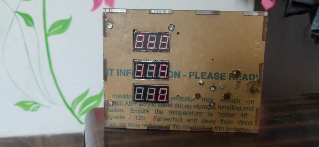
- Display the current temperature, set temperature and seconds of motion per hour.
- User interface to set the temperature and seconds manually with momentary push button.
Defining the problem.
- The problem was quite simple they have to reduce the size of their controller which they bought for around ₹ 3500/-
- Still this controller dose not have Solid State Relay inbuilt so to implement this as PID controller we need to invest another ₹ 400-550 per KW of load.
Ideation
There were Multiple methods to control the temperature and they are Proportional (P), Integral (I), derivative (D) so to get best results we can combine two of them like PI Controller or PD Controller but for controlling temperature it is beneficial to use the PID Controller. ill explain what each term dose.
Again we have to choose the display to be used for user interface as per customers requirement we need to implement 7 segment display as it is clearly visible from long distance. here we may choose between IC7448 (binary to seven segment decoder) and MAX7218 (I2C Interface for controlling 7 segment display.
I personally studied IC7448 so it was quite easy to work with so selected this for the first prototype.
MAX7218 is a IC that uses only 3 pins from microcontroller to communicate with Arduino and control 8 digit 7 segment display with ease. so in future we try to play around this chip.
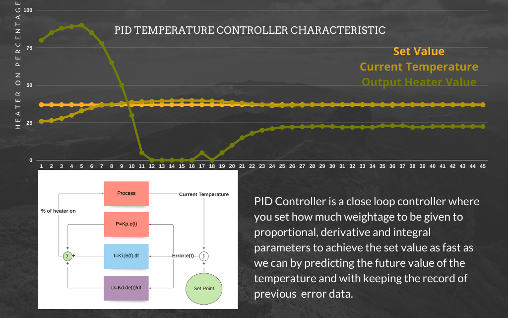
About PID Control.
Before starting we should know basic things required to understand PID control.
- Set value-: the value we set or the target value we need to reach in our case temperature 37.5 degrees.
- Current Value- The current value of environment basically data collected by the sensor in our case it is value of current temperature.
- Error -: it is the difference between set value and current value.
- Output heater value-: this value determines how much heat your heater will be providing. as 8 bit PWM pin Arduino can divide 0-5 volt signal into 256 parts 0-255 and here 0 corresponds to 0V signal and 255 corresponds to 5V signal. this value ranges from 0-255 mapped between 0-5 volts.
- Solid state relay-: This device gets trigger from 0-5 volts by signal from Arduino and decide the timing for which the SSR will be switched on 0V signal corresponds to 0 MS it will be switched on in each sec and 5V value corresponds to 1000 MS it will be switched on in 1 each sec. and in between say 2V value corresponds to 400mS of switch on time each sec.
- Proportional control-: When we calculate the heater value based on how big the error is it is called as proportional control we just multiply the error value with proportional constant which will be decided on how fast we required to achieve the targeted value.
for deciding proportional constant we take the extreme values of current temperature which in our case is 17.5 degree and set value is 37.5 degrees.
So we have maximum error of 37.5-17.5=20
We should run our heater on its maximum value i.e. 255 to make it totally on so our heater value should be 255 and
proportional constant (Kp) should be 255/20=12.5
So error of 1 degrees will set heater on for 1*12.5=12.5% on. and respectively. - Derivative control-: Use of this control is to check how fast your error is changing and accordingly change the output value.
Say if temperature is increased by 1 degrees in 1 sec then rate of change of temperature will be dT/dt=1/1=1degrees per sec.
And if you have already reached 37 degrees then it should know that in next 1 sec value will be 38 and more then required and hence this proportional control comes into game and reduce the output value even before reaching the the value.
Basically derivative term tries to predict the future curve of the temperature and accordingly makes the changes.
This value is selected based on how fast response you want say if rate of increase of temperature is more while reaching the set value then we need a smaller value of derivative constant say Kd. - Integral control-: Integral control keeps track of past. it calculates the inaccuracies happened in the past and modify the output accordingly. Integral constant Ki depends on how much strongly you need to take the action based on past inaccuracies.
Say over past five minute error was reduced from 5 degrees to 3 degrees so what the integral control dose it integrate the path followed by the current value of the temperature over x axis with limits of set value and current value which gives the area of the error and multiplying this area with integral constant which will be smaller for higher inertia system in-between 0.01-0.2. - Currently set values of Kp, Ki and Kd are 10, 0.2, 10.
- As a prototype we decided to work with ARDUINO, IC7448, 3 digit 7 segment display, a DS12 temperature sensor, and Arduino screw shield. all the items are available on local electronics component shops in Pune or online too.
- Here is the link to real time values of change in temperature and heater output value.
https://drive.google.com/file/d/1xJEjiBhb2lZSCntoqARB145_q08LprEB/view?usp=sharing
Prototyping.
As a prototype we decided to work with ARDUINO, IC7448, 3 digit 7 segment display, a DS12 temperature sensor, and Arduino screw shield. all the items are available on local electronics component shops in Pune or online too.
We decided to use following items
- Arduino UNO.
- 3 digit 7 segment common cathode display.
- 7448 BCD to 7 segment encoder.
- Arduino screw shield.
- DS18B20 Temperature sensor.
Breadboard test of controller.
Here by making all the connections with jumper wires we tested the circuit if everything works fine, and yes everything was perfect.


Zero PCB Built of the prototype
After checking everything was fine we moved on zero PCB built for the controller and hence every connection made by soldering the every component at its desired position.


Designing the enclosure and adding few push buttons for user interface.

We have completed the working prototype which will operate around 0.1 degrees of accuracy after 40 mins.
Implementing the Controller and comparing with existing.(21st sept 2021)
A visit to Mr. Anil Gades workshop we placed two controllers side by side the pre existing one and one we made. We compared the temperature values.
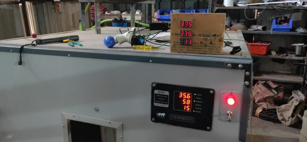
It is found that the controller giving the error of 1.9 degrees is the one they purchased and the one giving correct reading was designed by us, so at a first glance our system looks much more reliable then the pre existing once.
Implementing a DC motor.
Currently they are using a AC motor with 4 rpm and 400N-cm torque, so we decided to implement a motor more then double the torque of previous one.
Currently we need to add a motor to provide the required motion to the eggs, so we have purchased 4 RPM motor with the torque of 846.2 N-cm. The motor is already purchased but visit to workshop and testing is remaining.
Test results.
Stay tuned for the results, we will add the results once the tests are completed.


